
Remote Control Cockpit
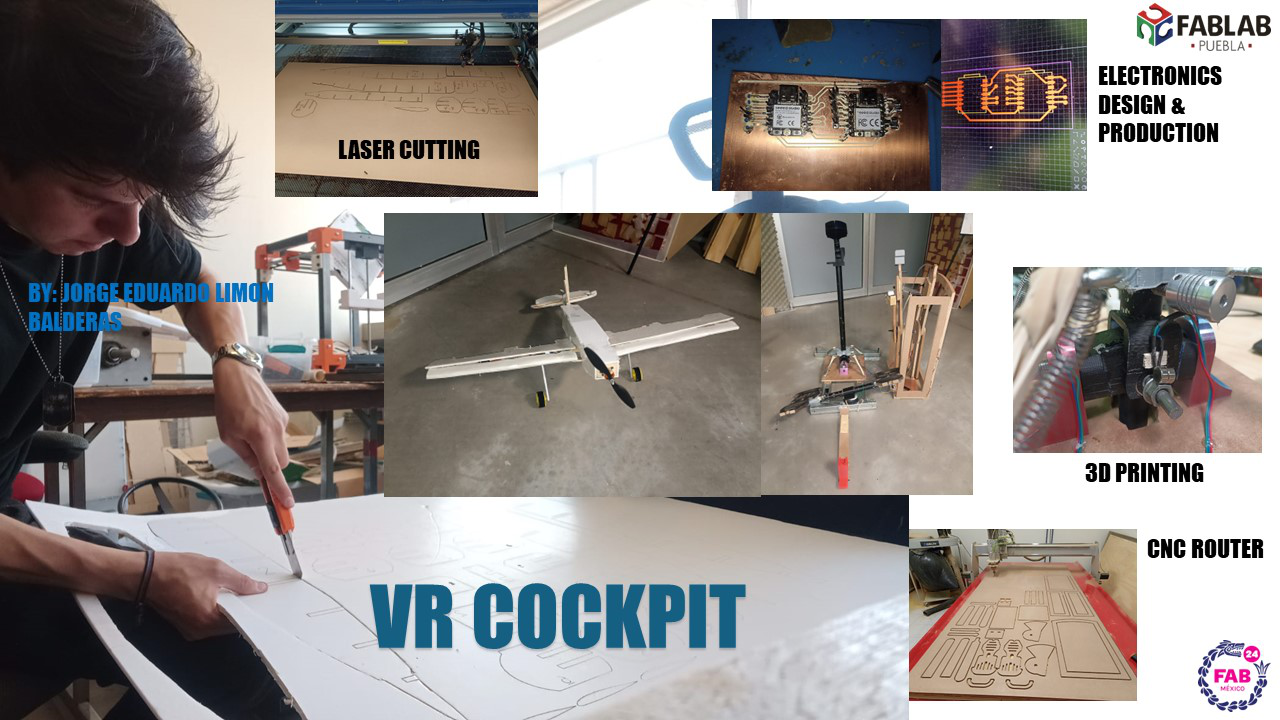
For my final project, I will be doing a Remote Controlled Airplane, which is controlled by a center stick, throttle, flaps selector, and pedal rudder, simulating a cockpit.
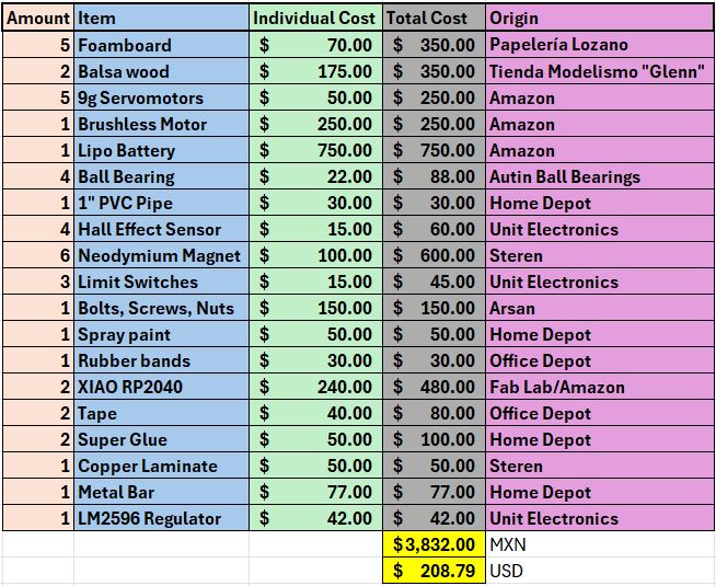
Bill of Materials
Introduction
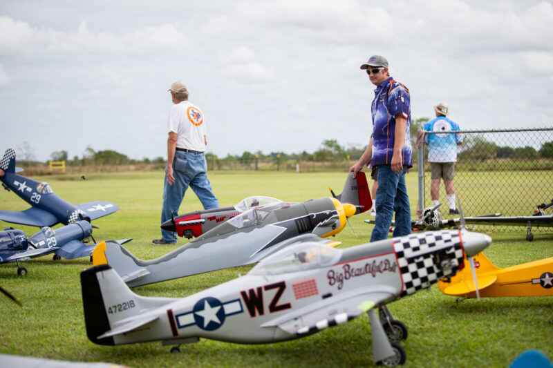
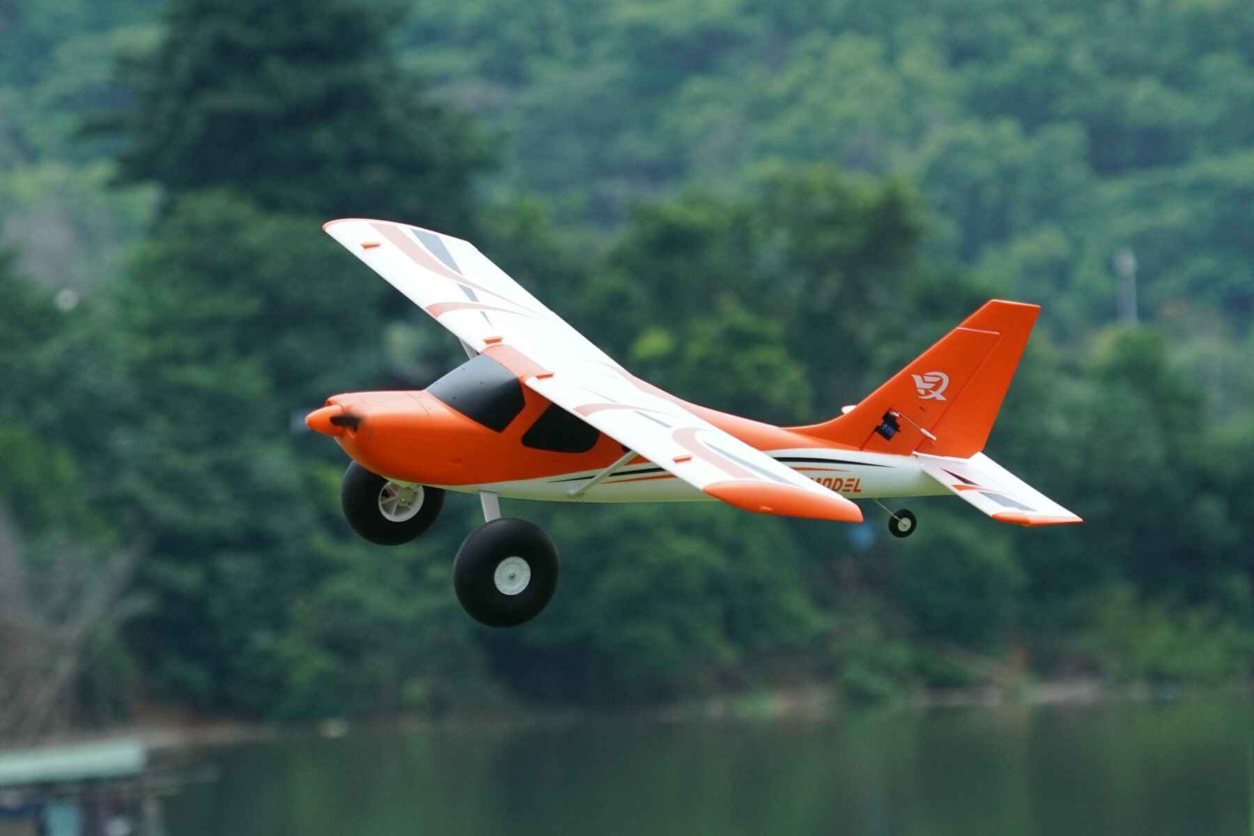
RC Planes are scaled-based aircraft that are controlled by a remote transmitter, allowing the plane to be unmanned. They are usually a hobby and have a very large community, support and market, and even more professional models are being used for commercial and military purposes, better known as drones.
In the hobby niche, there are endless varieties of RC planes, like long range gliders, stable trainer models, high speed sports planes, scale models of actual aicrafts, etc. They are usually controlled by a hand held, controller like transmitter that allows the user to fly the model with high precision while being portable.
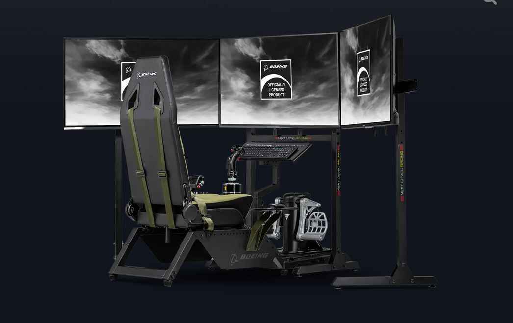
But more reciently, and addition product that reached the RC and software simulator market have been realistic cabin like peripherals that imitate an actual cockpit. Giving the user a more realistic and immersive feel to controlling a plane. An example of this product is the "Flight Simulator Boeing Military Edition", with a price tag of $799 US dollars.

The objective of my project is to create a minimalistic cockpit-like controls that allows the user to control an RC plane.
Sketch
At the begining of Fab Academy, we were asked to sketch a posible design for our final product. The project I had in mind was a VTOL capable RC plane, with a portable controller and a POV headset that transmitted live video from the plane to the user.
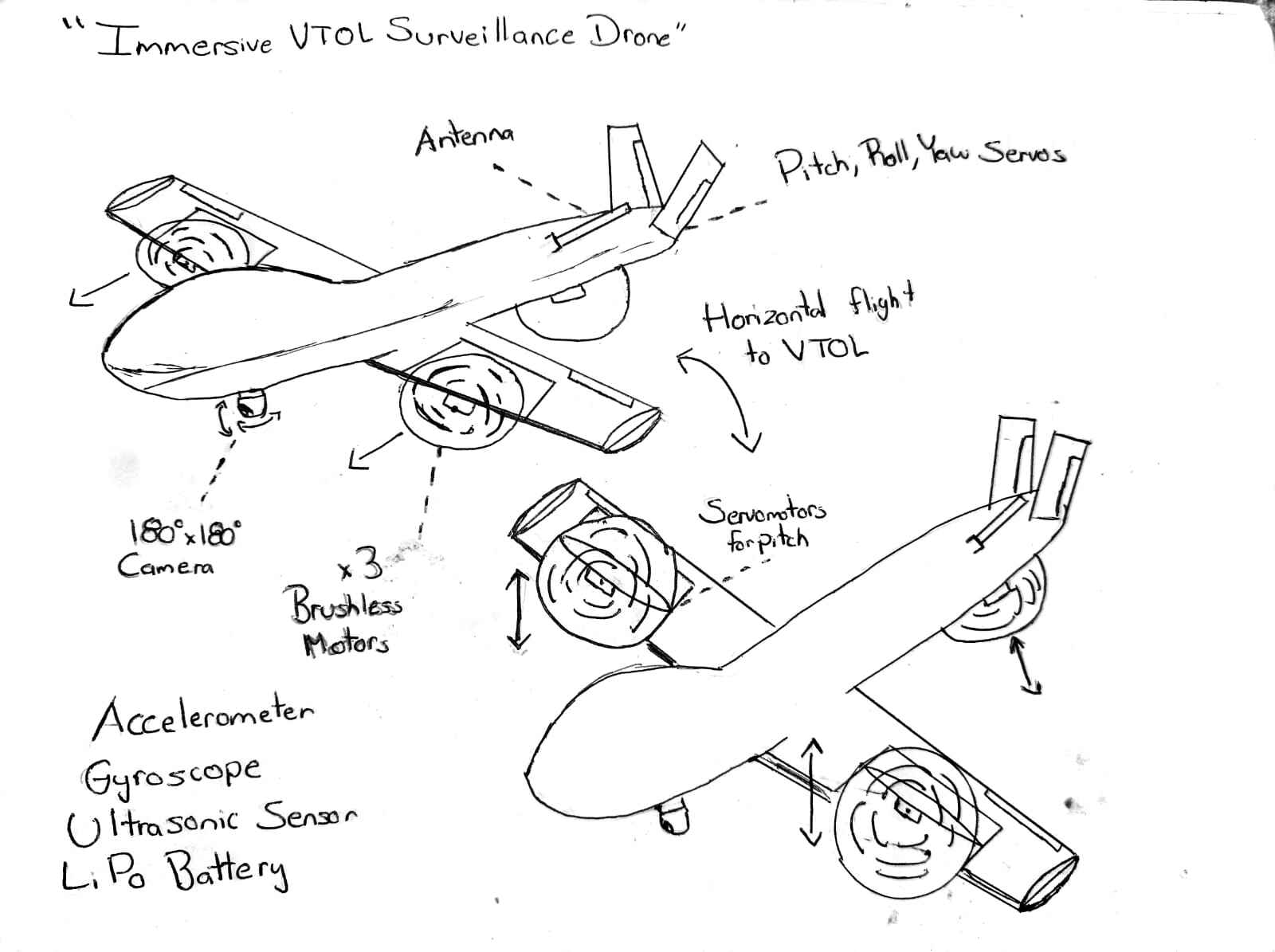
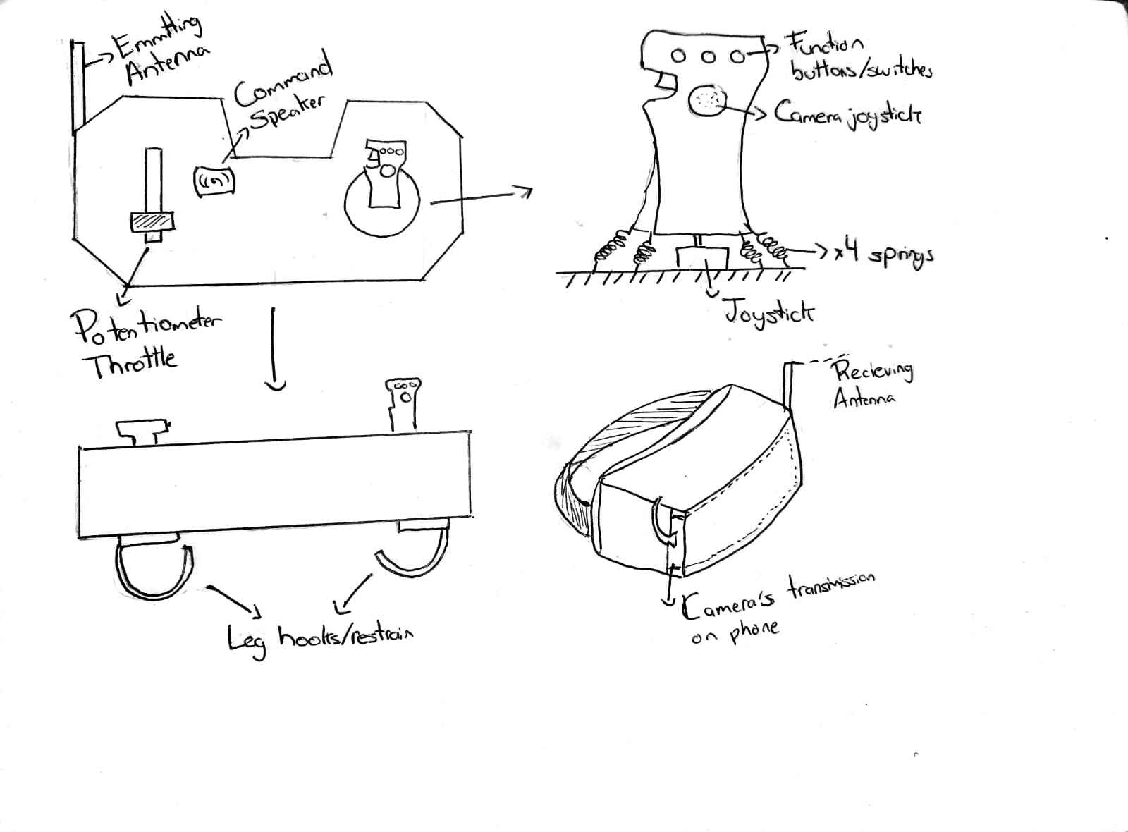
Since then, due to time and capacity limitations, the proyect has changed to a regular RC plane, and the controller became more of a physical simulator of airplane controls, while also skipping the POV video transmission.
Bill of Materials
First Aircraft Prototype Construction
When constructing an RC plane, the selection of the materials and overall build is crucial, as this will determine how well the plane will perform and fly (if it does at all). Here comes a quick bit of airplane theory:
The main flight controls of an airplane are the following: Ailerons, Flaps, Rudder and Elevator
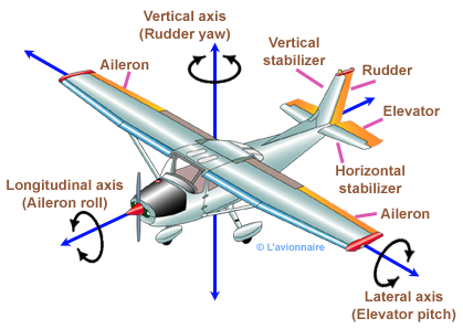
These controls are determined by the inputs of the pilot, giving the plane altitude and direction. These are the ones that will be controlled by the inputs made with the controls.
There are 4 main forces acting on an airplane during flight: Lift, weight, thrust and drag
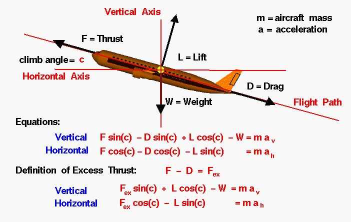
The thrust is the force made by the motors, and it does this by pushing air in the opposite direction the plane is flying. The lift is and upwards perpendicular force created by the flow of air through the wing, which counteracts the weight of the plane, the weight is just the mass of the airplane, and drag is the friction created due to the plane crashing into the air particles at high speed, causing the plane to slow down. There is a very important relation between this forces, called the Thrust to Drag Ratio, which simply means, how many kg or pounds does the motor produced compared to the total weight of the airplane. Most commercial planes have between 0.3 and 0.4 T/W Ratio, meaning the motors create about 0.3 kg of force per every kg of the total weight. While other planes like fighter jets have close to 1 to 1. When it comes to model RC airplanes, sources say it can fly between 0.3 to 0.4 for slow moving gliders, up to 3.0 for 3D acrobatic airplanes. But for a normal flying plane we can work with about 0.8 to 1 T/W.
All this comes because, if we have a fixed motor for our aicraft, meaning a fixed amount of thrust, we need to keep the weight as low as possible. Most RC planes are made out of one of these 3 materials: Balsa wood, foam, or Low weight PLA. Each has its own advantages and disadvantages
- Balsa: Very lightweight and strong, but also expensive and difficult to find
- Foam: Also very light and cheap, yet not as strong as balsa and it is sensitive to heat or chemicals
- Low Weight PLA: Very precise models with 3D printer and very durable. It is usually heavier than foam or balsa and can be brittle.
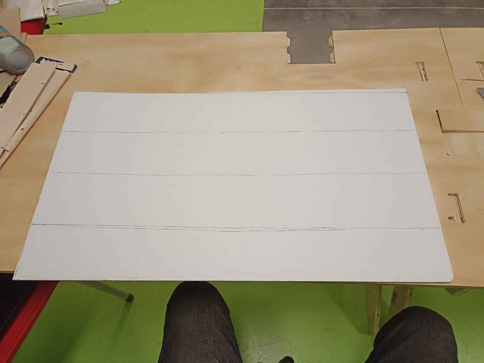
For me, the best option was doing foam, as I it is very available and lightweigh, which I got at a local crafts store. The ones I bought were 5mm 80x100 cm sheets, that cost me around $70 pesos each, or around $3.5 each one.
The entire sheet weighted around 350 grams, but it also had a paper cover on both sides, which I decided to peel to see the weight difference.
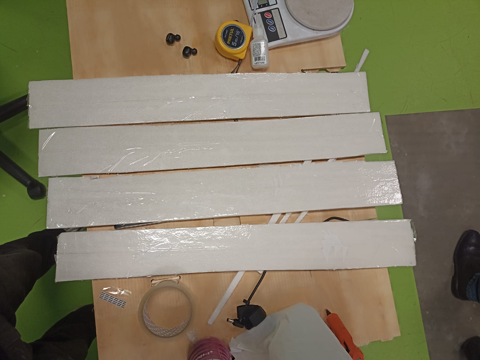
And to my very pleasant suprise, it weighted less than 150 grams, meaning it would be an excellent material to build my plane out of. Unfortunately, this came with a disadvantage, without the paper, the foam would easily snap and break when being folded. So, what I tried to do was cover the foam with tape to prevent it from breaking.
This worked suprisingly well, as it could bend in any direction and not snap, while keeping it very lightweight.
So I decided to make a quick fuselage prototype to test this material.
The first step was to model what the approximate size and shape of the airplane would be, so I created a 3D model of a scale airplane in Solidworks
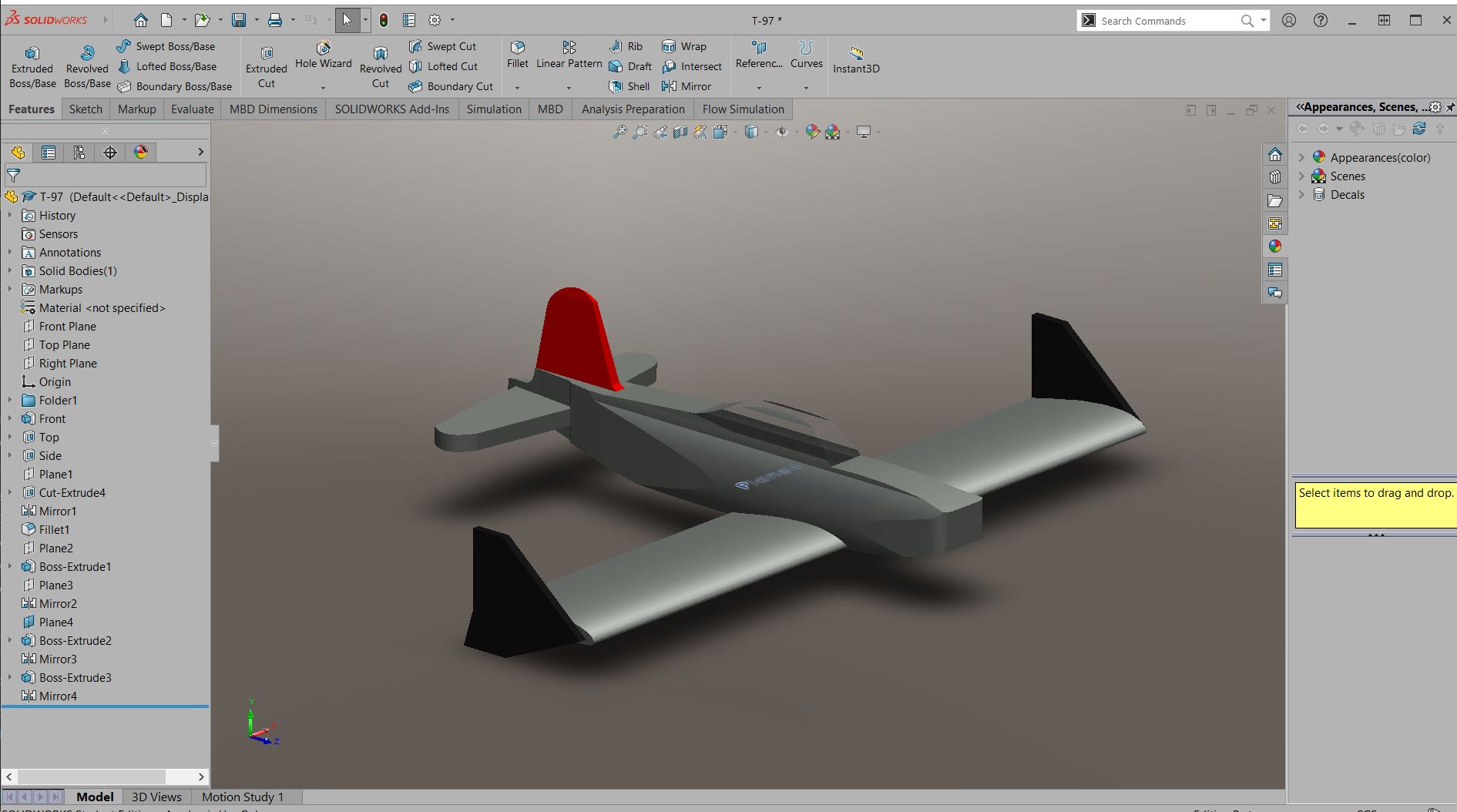
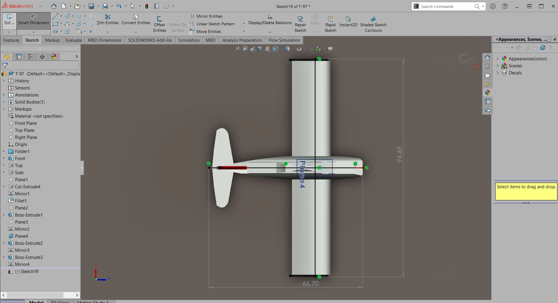
I exported the model as an STL file to move to the next software: Slicer for Fusion360. This software allows you to take a 3D object and it will slice it according to your parameters to make 2D patterns that can be cut out of flat materials to create an assembly
You can download the software using this link but disclaimer, the app is no longer given support by Autodesk and may not be compatible with you current Fusion360 version. But you can give it a shot
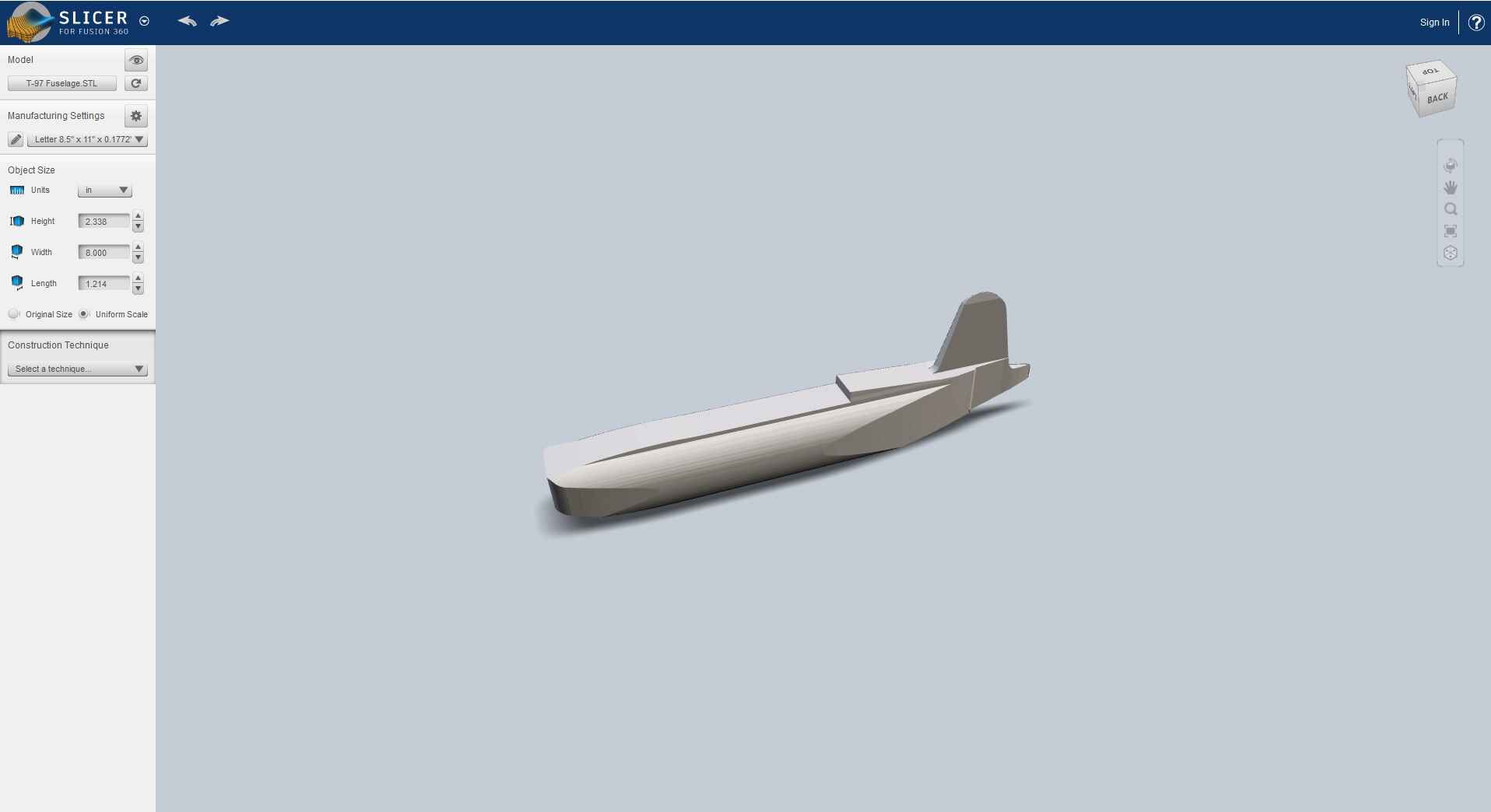
Inside slicer, you import your STL object
 /span>
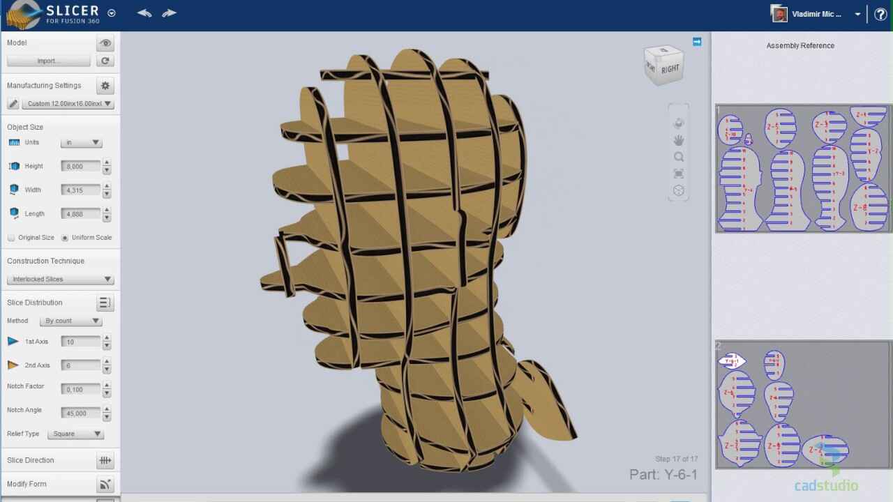
Now, you will need to customize the model to get a proper slice format. Firstly, change the size of your sheet to the one you will be cutting in. I gave mine 102cm by 80cm and 0.4cm thick (I know the original board is 5mm but when you take out the paper it reduces to 4mm). Then change the object as it may not be imported with the rigth units you gave it in your CAD software, and then select a construction technique:
The most used slicing patters are the following:
- Stacked Slices: Cuts the model into horizontal slices that can be stacked.
- Interlocked Slices: Creates a grid of intersecting slices that lock together.
- Radial Slices: Produces slices arranged radially from a central axis.
- Curve-Based Slices: Allows slicing along custom-defined curves.
In my case, I chose the Interlocked Slices option, and adjusted the ammount of slices on the 1st and 2nd axis, to give me the result I wanted

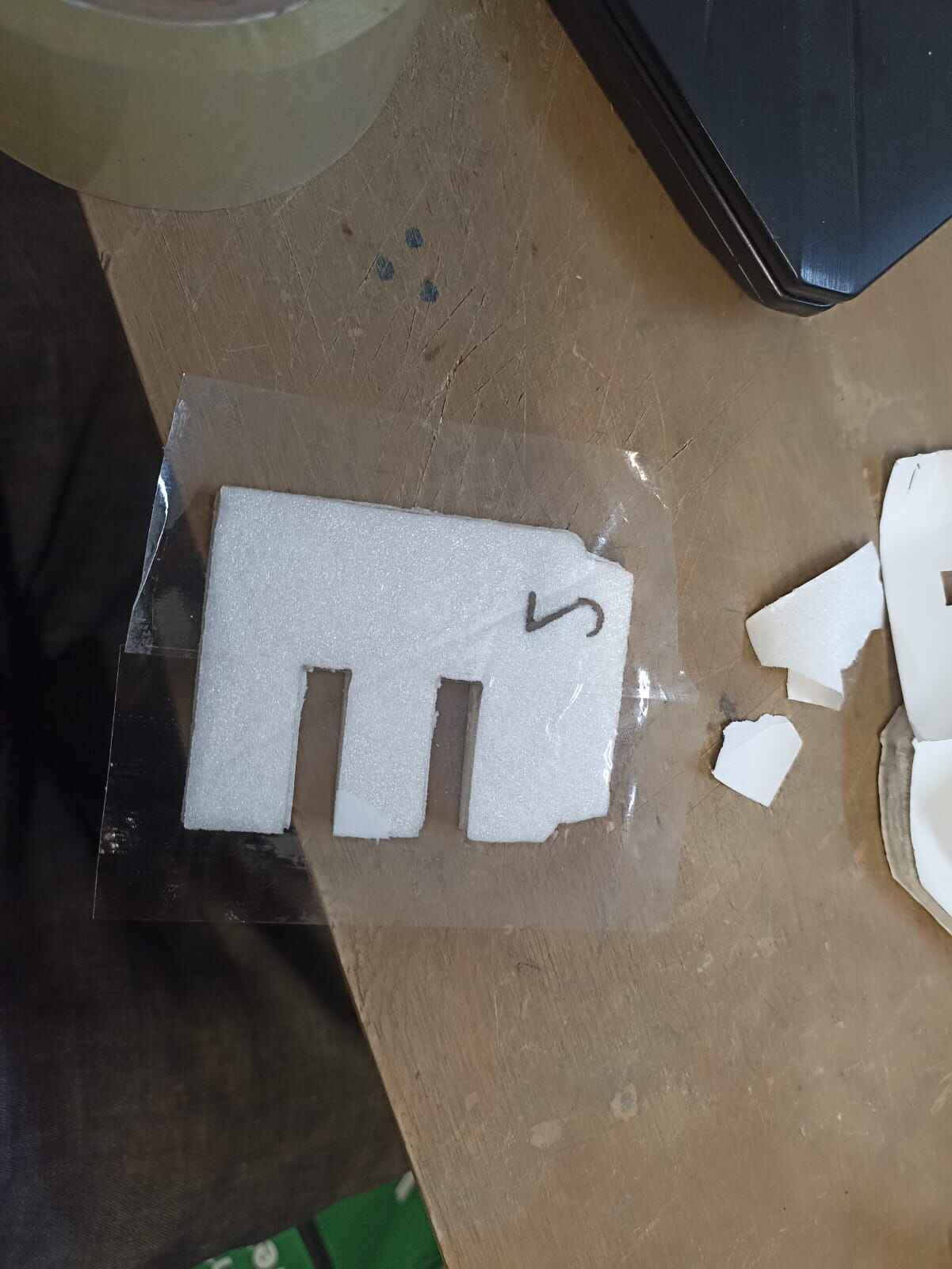
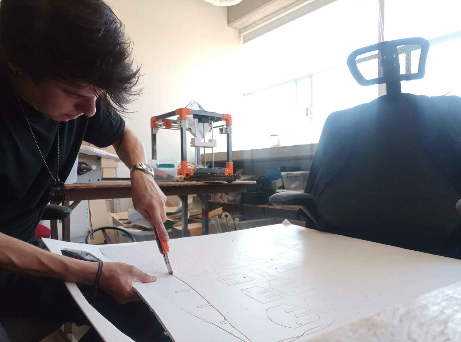
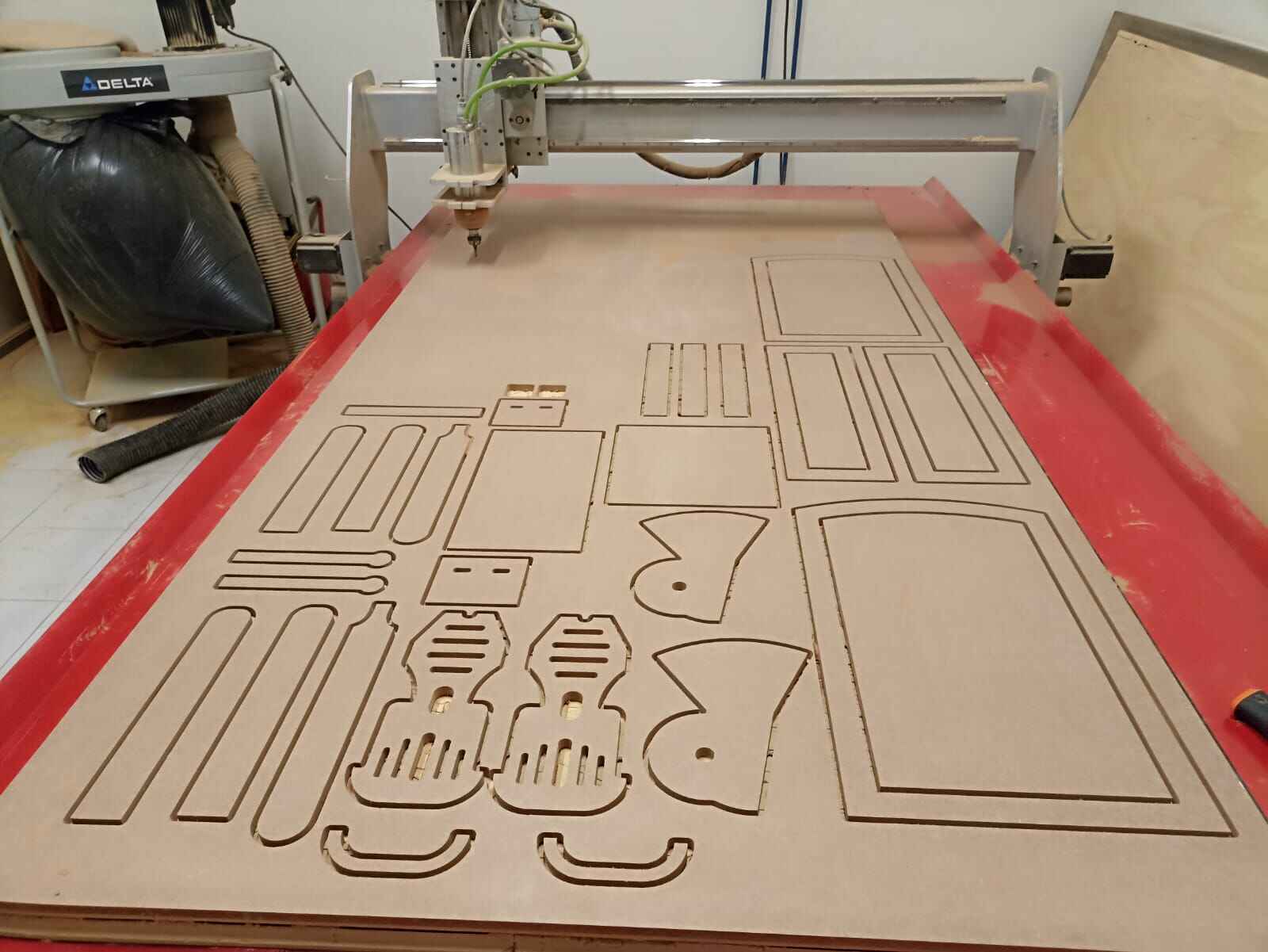
Now you can visualize on the right side how the cut will look on your board. Click on get Plans to export it as DXF. These same DXF files can be used to cut our pieces in the laser cutter. Firstly, I cut the design in a 3mm MDF sheet to have the individual pieces so I could trace them in the foam board. (You should probably not do that, just cut the design out of the foam board itself.)
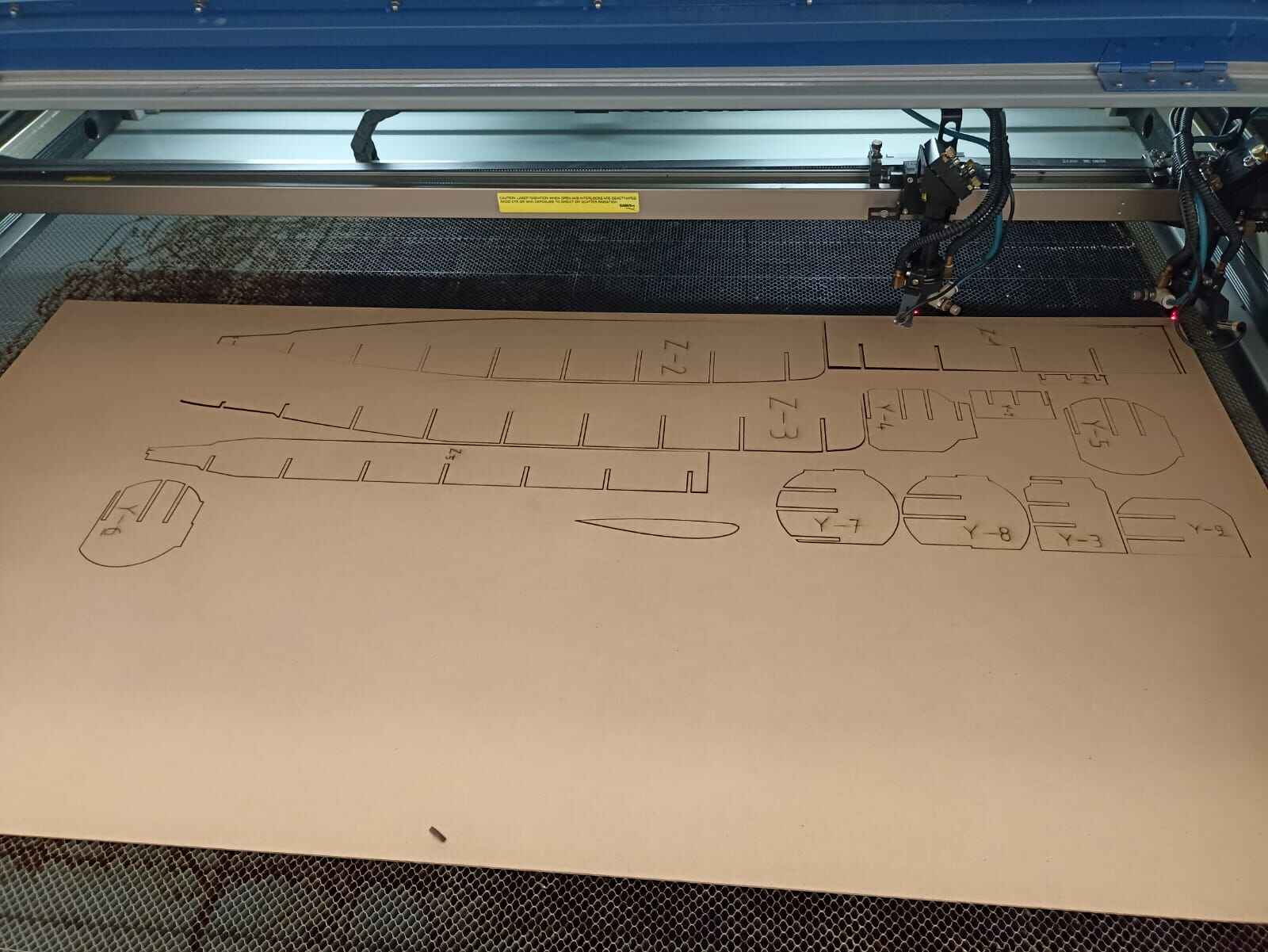
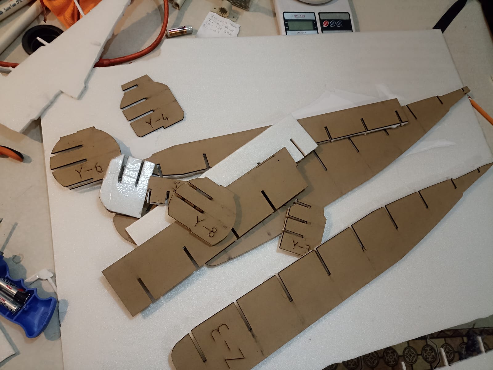
After I traces and cut the pieces from the foamboard, I could make the prototype assembly.
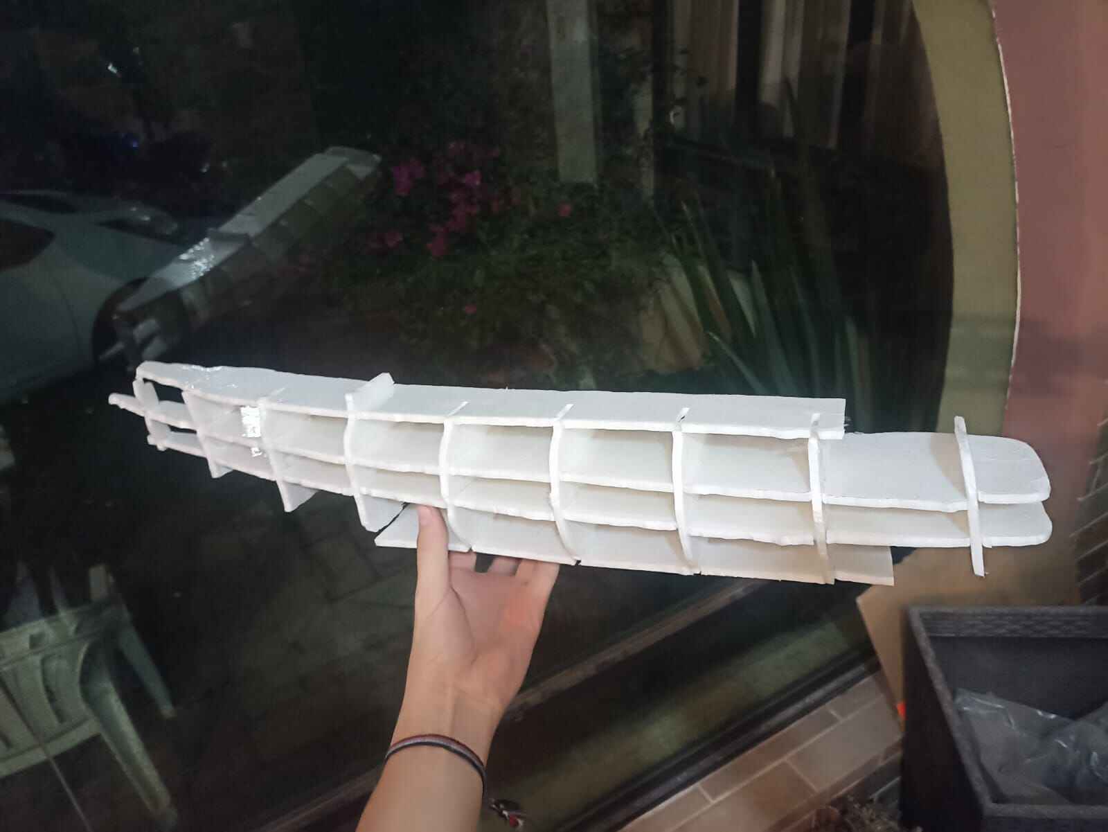
Then, I weighted it on a scale.
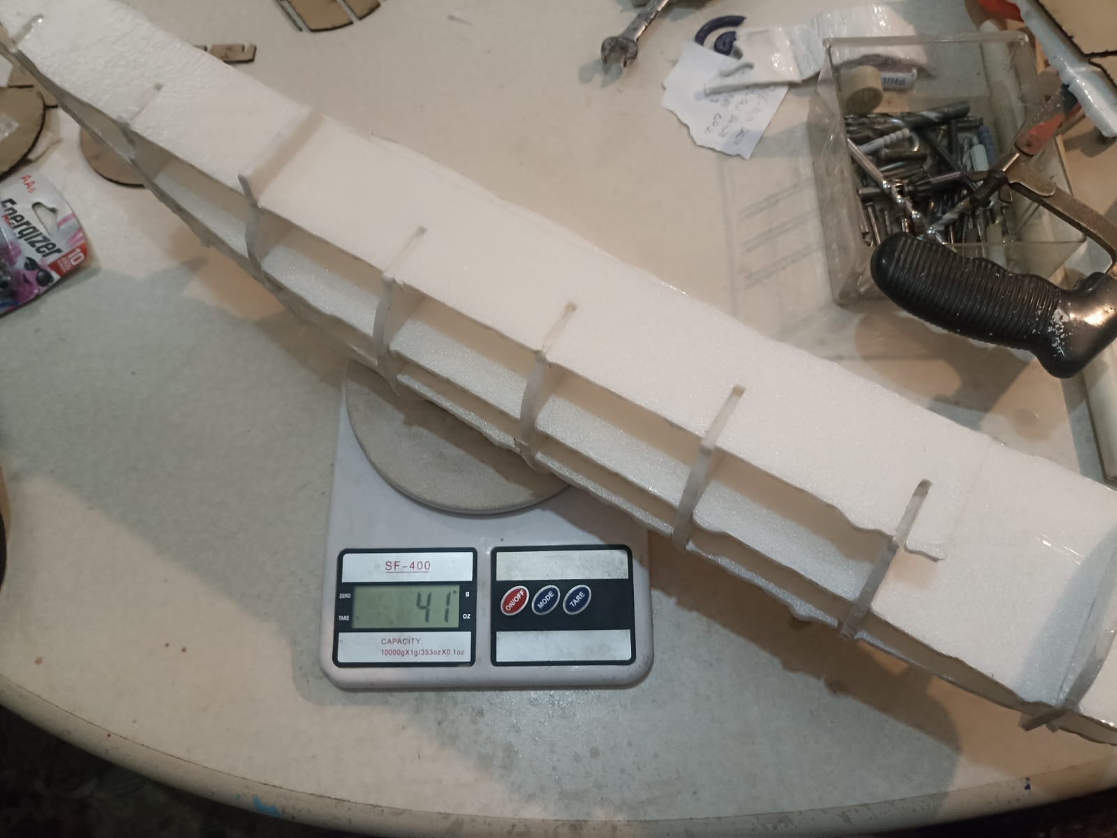
As you can see, it´s 41 grams; extremely light. On the other side, it was very flimsy and did not really hold it´s shape, as yo can see from the previous picture, even curves up. To address this, I did an itteration in Slicer, where I made the thickness double, and I would cut the slicer output twice, and paste the pieces together to make it a double layer so it hopefully hold better.
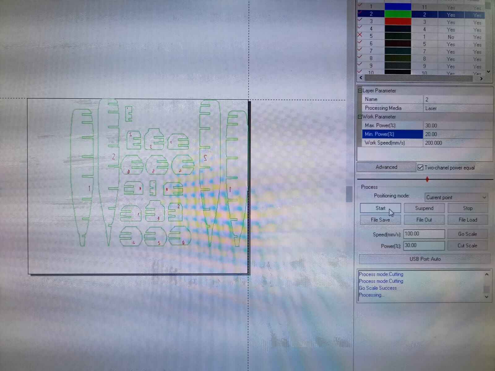
This time, I cutted the slices directly on the foamboard with a speed and power 30%-20% power and 200 mm/s work speed. This is actually the parameters used for engraving on MDF but I wanted to try on the foam.
Note: The videos look very low quality since I had to compress them so the webpage wouldn´t weight 100 mb, you can´t really see the pieces in this video but the next ones can be visualized better.
Once cut, I realized the matching pieces were either offsetted or incompleted, probably because the foamboard moved while the laser was cutting.
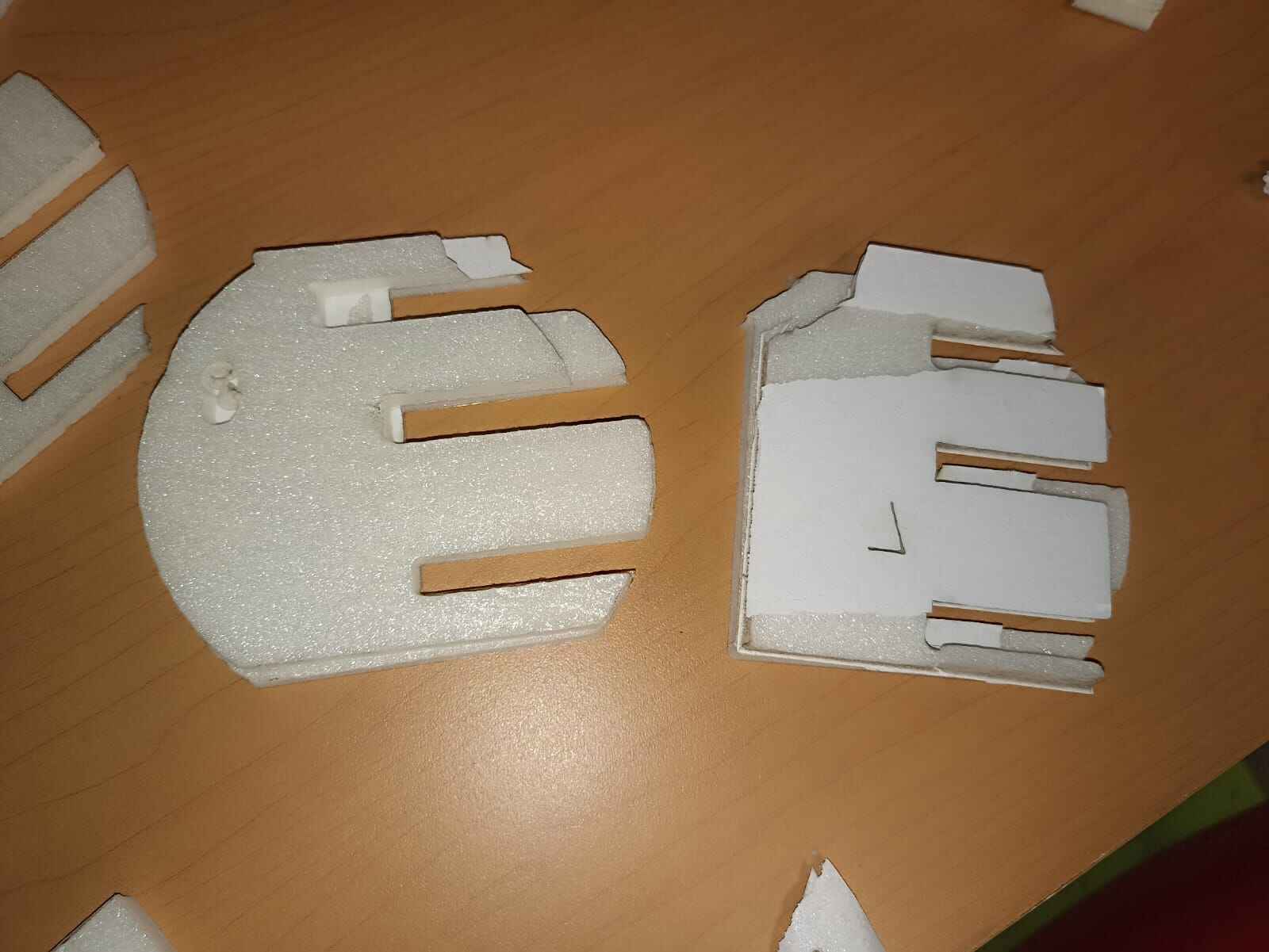
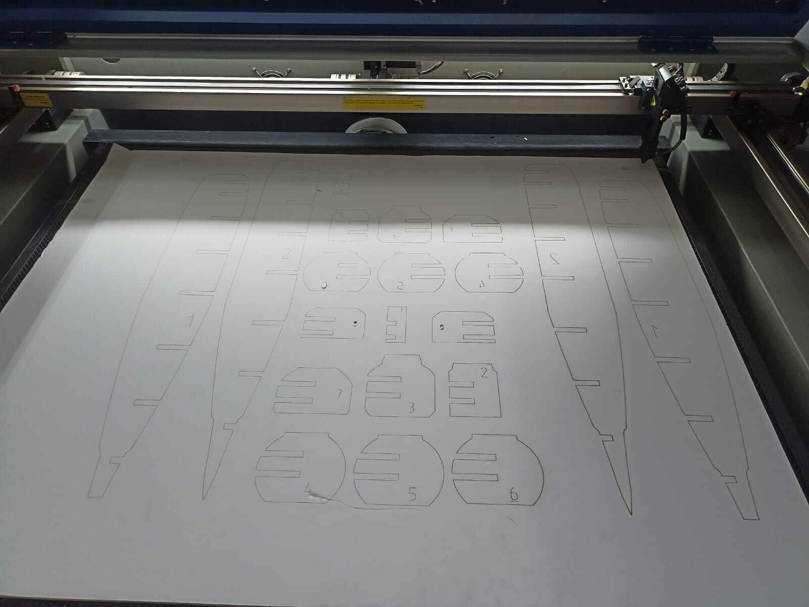
So, I decided I would cut it again but securing the board with tape and without removing the paper from the foamboard. And this was the result:
The issue now was, the cut did not go all the way through the board, most likely due to the paper, so I had to cut finish cutting the pieces with a knife.
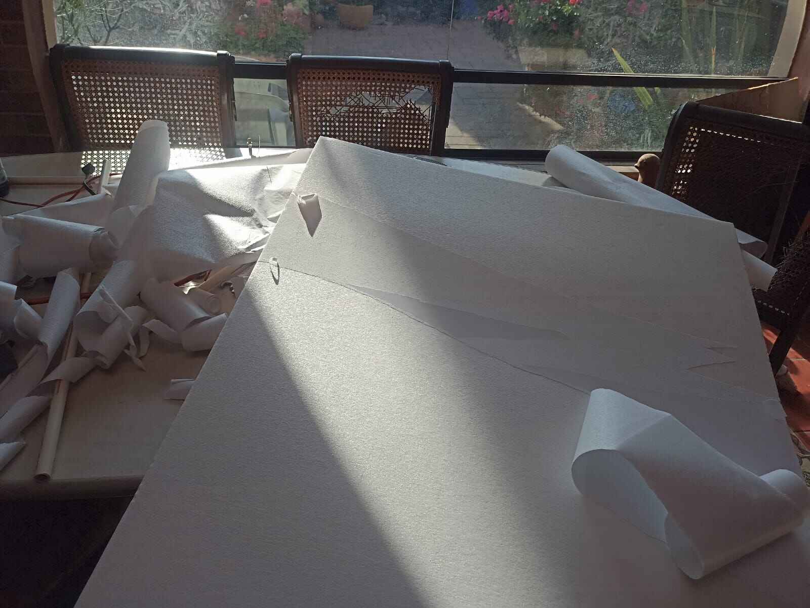
After every piece was cut, I wrapped each one with tape and glued the matching parts together using superglue, so I could make the assembly
Sidenote: please don´t mind the mess behind in the pictures, Fab Academy ain´t easy...
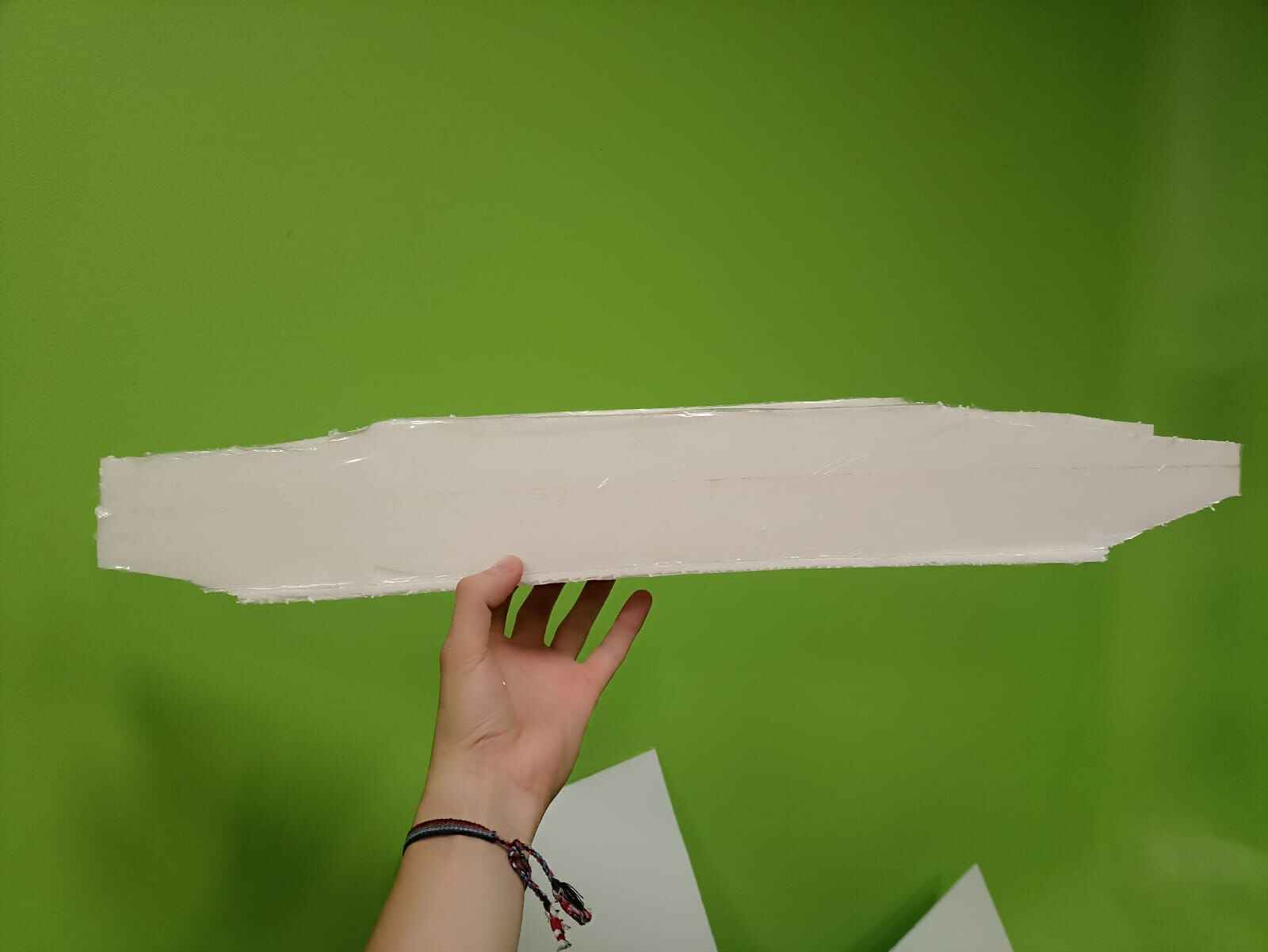
Once I had the fuselage prototype, I decided to reinforce some weak spots I thought could break with balsa wood I had from a previous project.
Then I decided to test the strenght and integrity of the fuselage by running the most rigorous and sofisticated test I could think of; throwing it at a wall
Impecabble
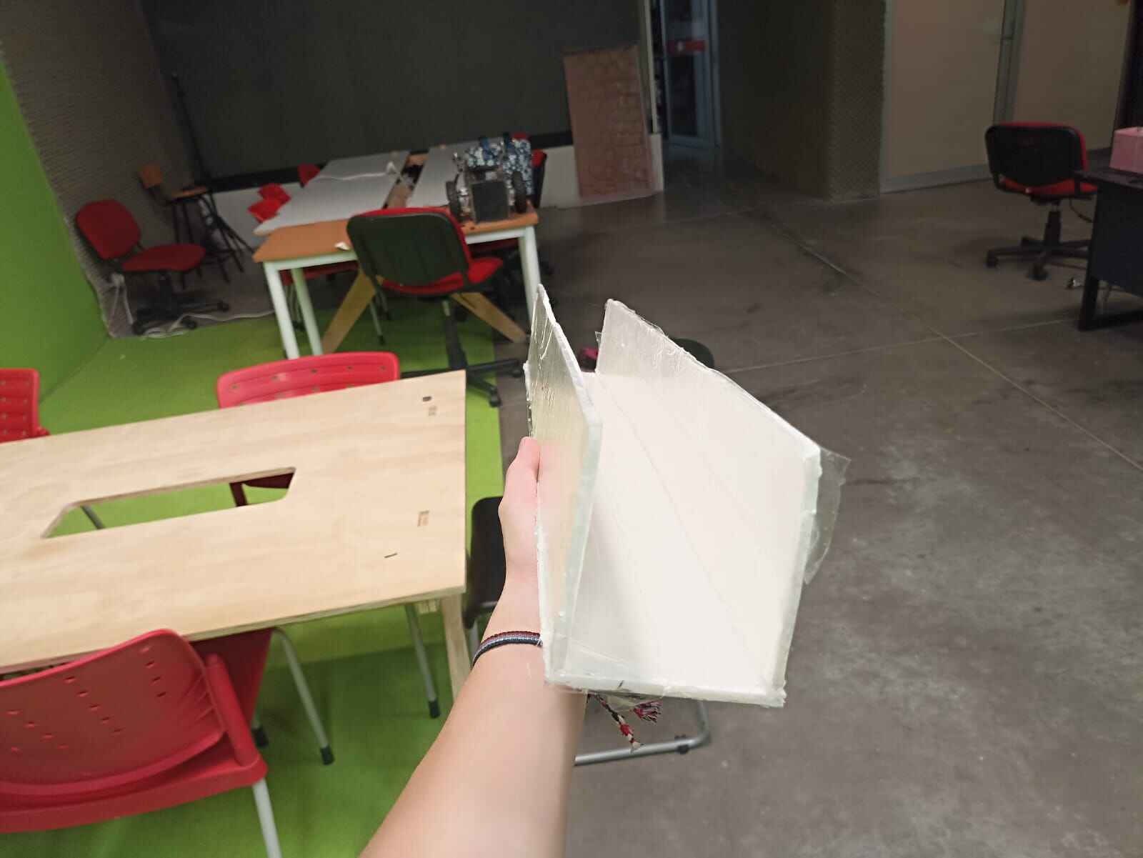
Next test was adding the walls of the fuselage. I used the flexible property of the foamboard to cut rectangular pieces and bending them to fit the sides, but also leaving space on the top and bottom so I could continue to make work on it later on.
Wings
Once we have the base of the fuselage, we can move on onto the wings. On my CAD design I had a total wingspan of around 95cm. Considering the fuselage with is 11 cm, that leaves us with 42cm for each wing. While making the wings, I decided to make them with a taper. Wings usually and more often than note, are inclinded at a certain angle to achieve certain aerodynamic characteristics, like less drag, better life amongst others.
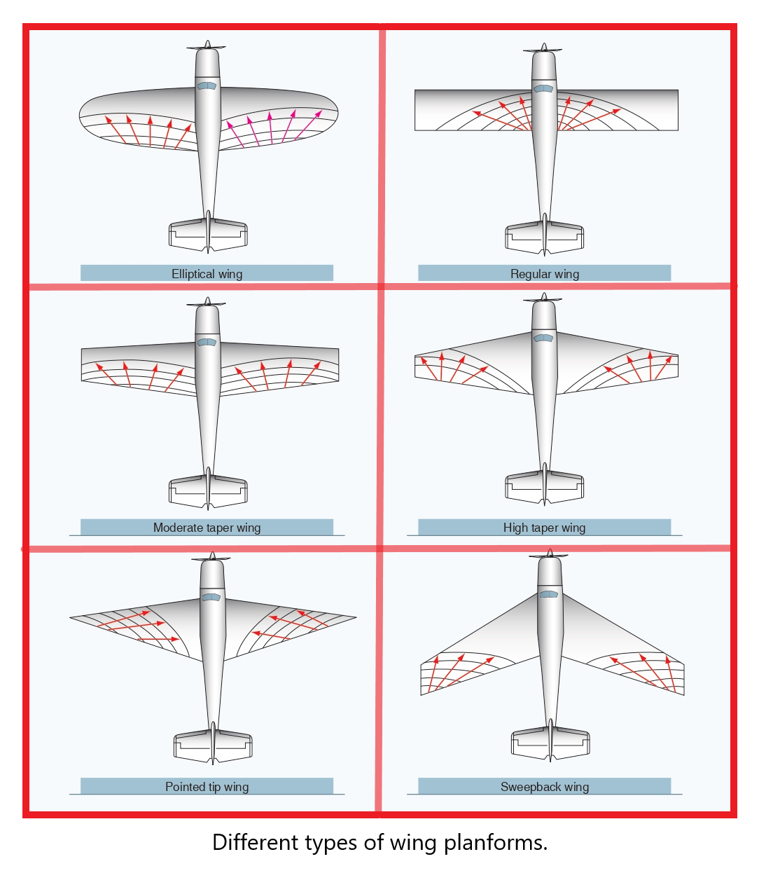
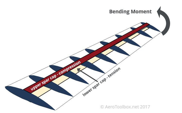
On model airplanes the difference it makes is almost negligible, regardless I went with a back swept design, meaning the back part of the wing is angled towards the front. Airplane wings are constructed under the base of "ribs", meaning that the whole surface covers separated sections of the airfoil, making it structurally stable while also lightweight.
Something we can easily do in Slicer again, this time instead of interlocked slices, we do stacked slices. Giving us transectional cuts of the wing.

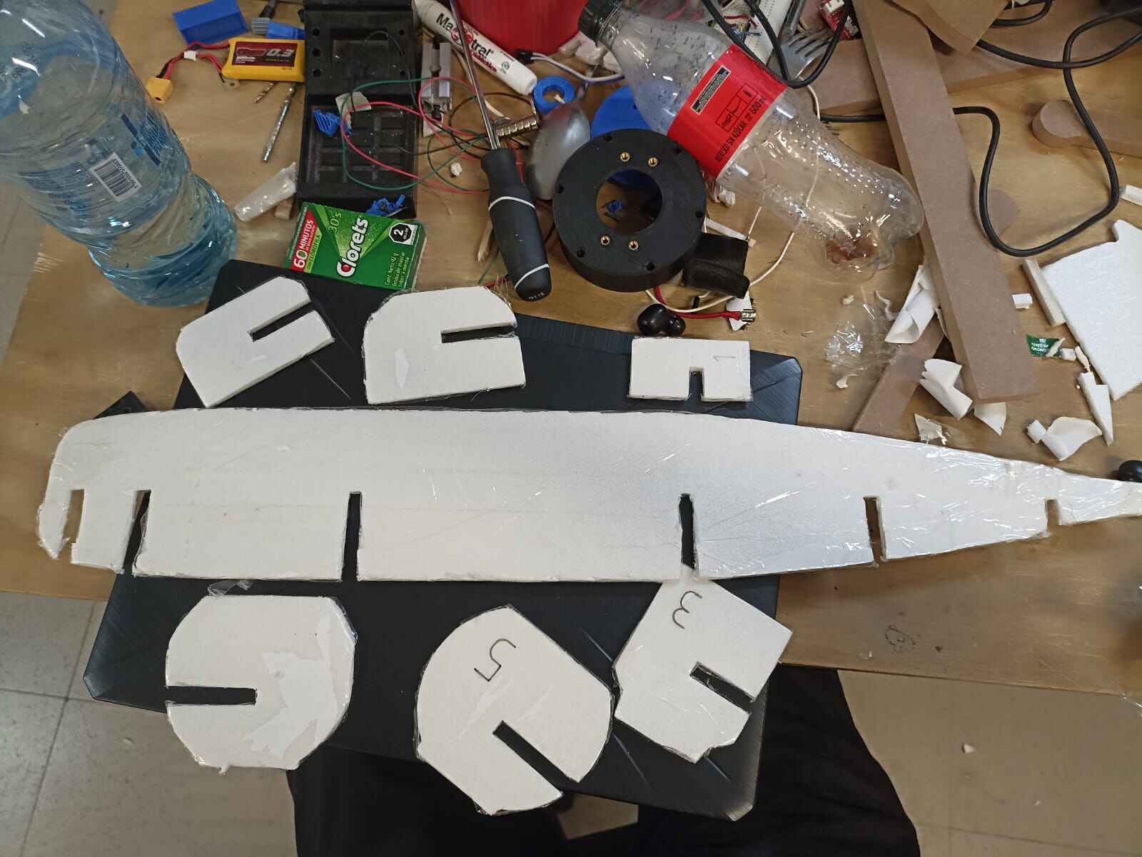
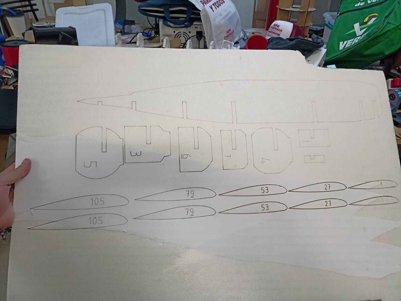
From the DXF file we get, we can chose the ribs we want to use and cut. After adjusting the wing size, the design came with a total of 105 different slices, then I deleted all except for the 105, 79, 53, 23 and 1st rib
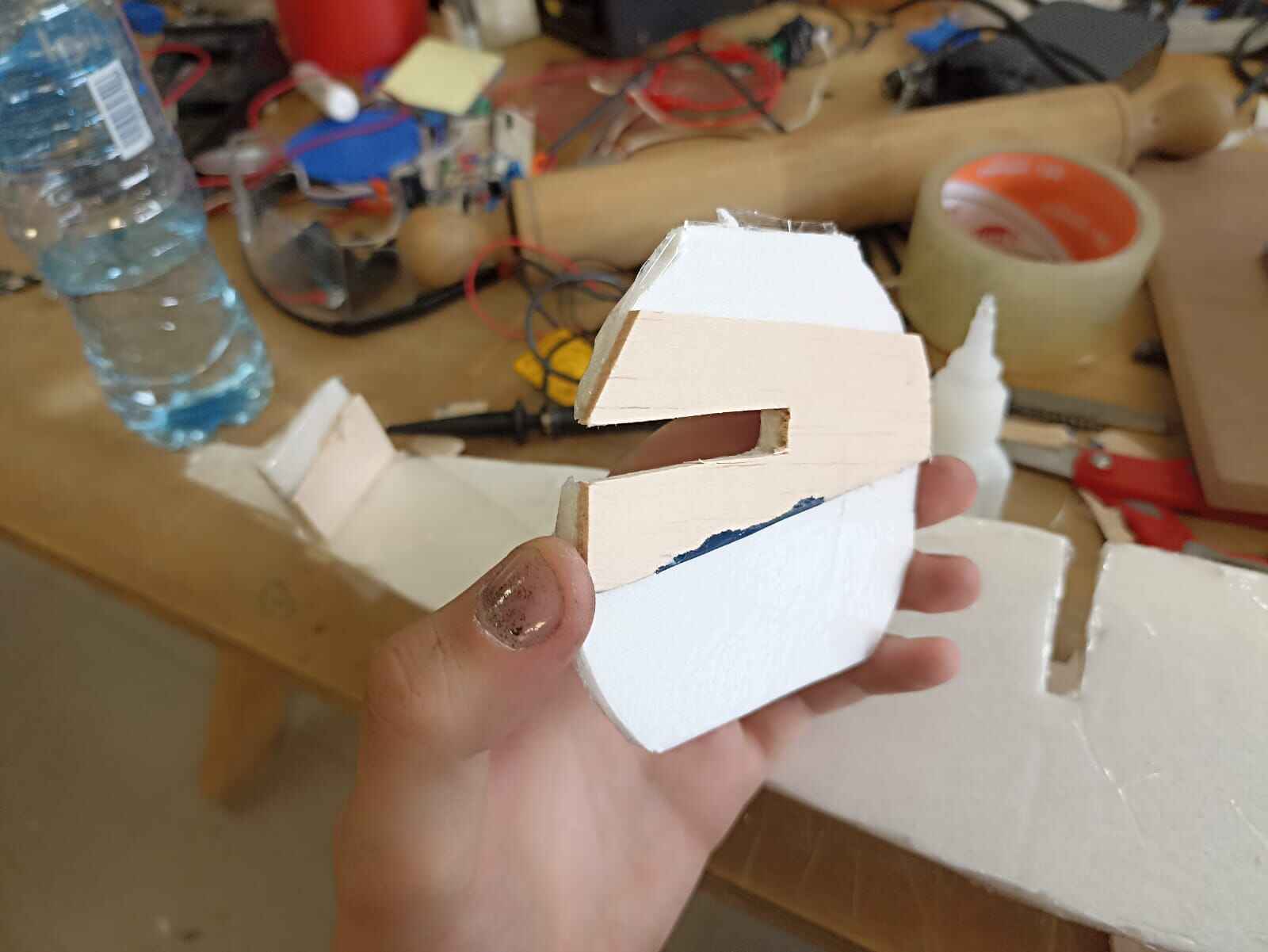
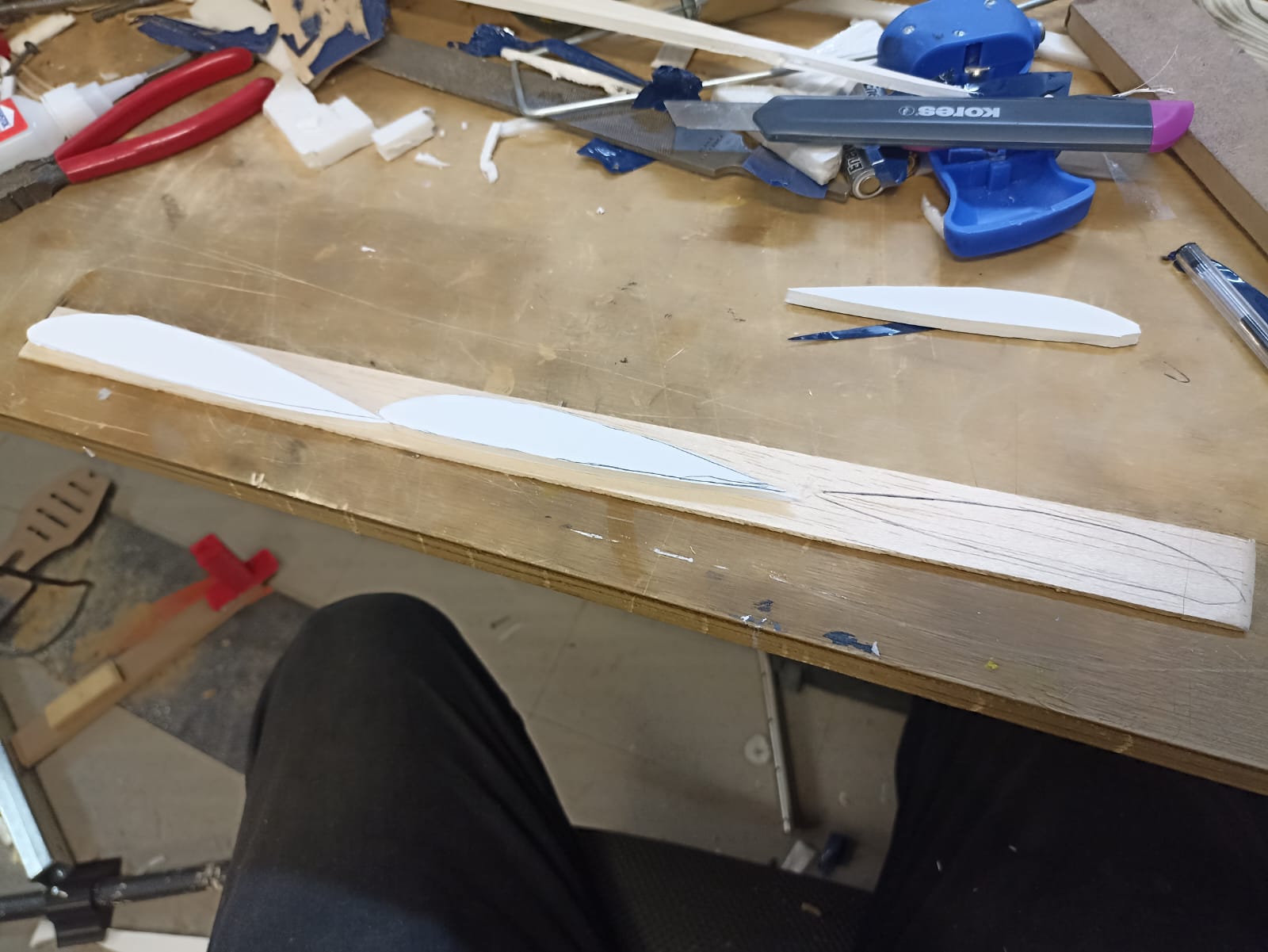
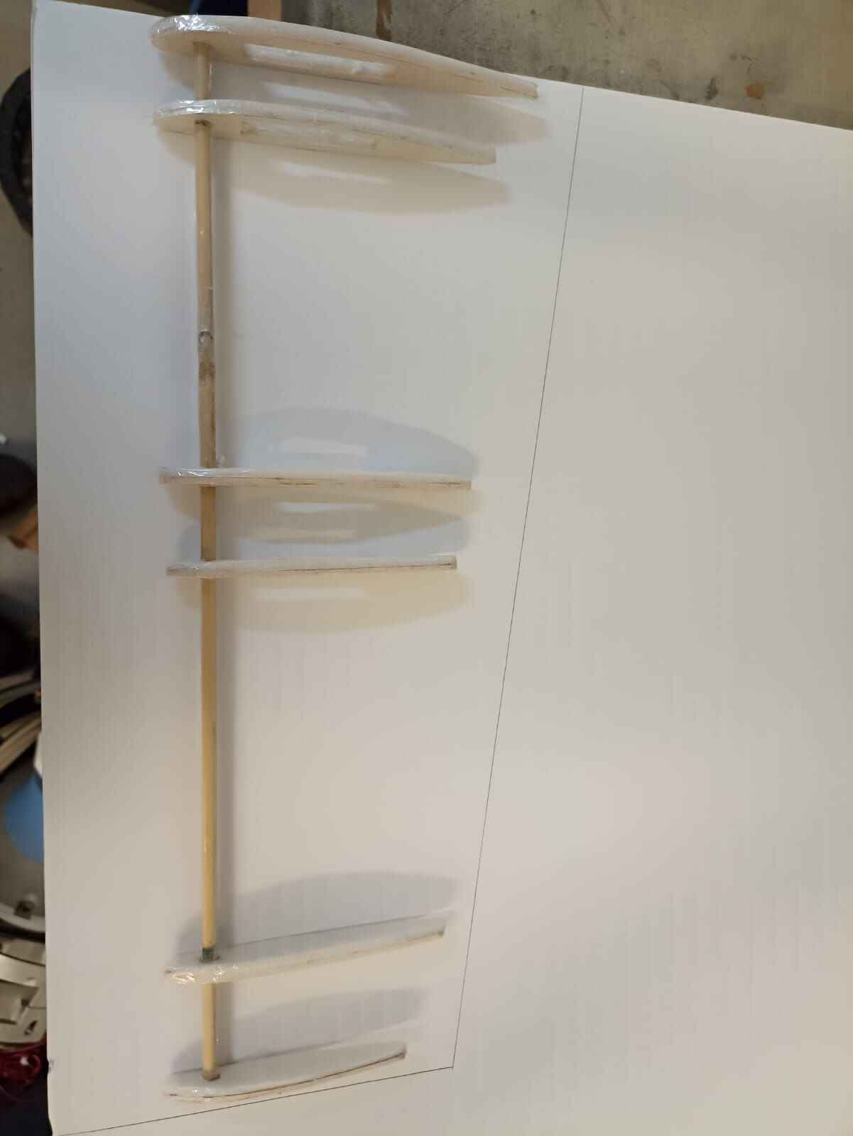
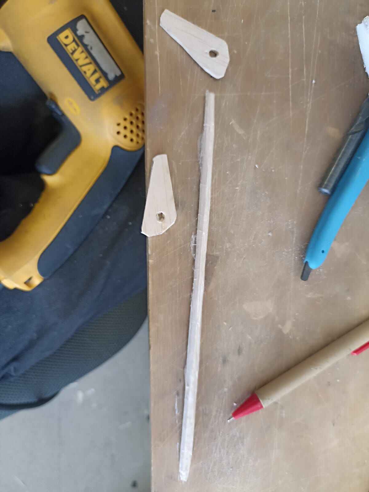
Once I had the foam ribs, I felt they too were too flimsy and could easily break or collapse, I did copy of the ribs on balsa wood to paste them to the foam ones and hopefully make them stronger
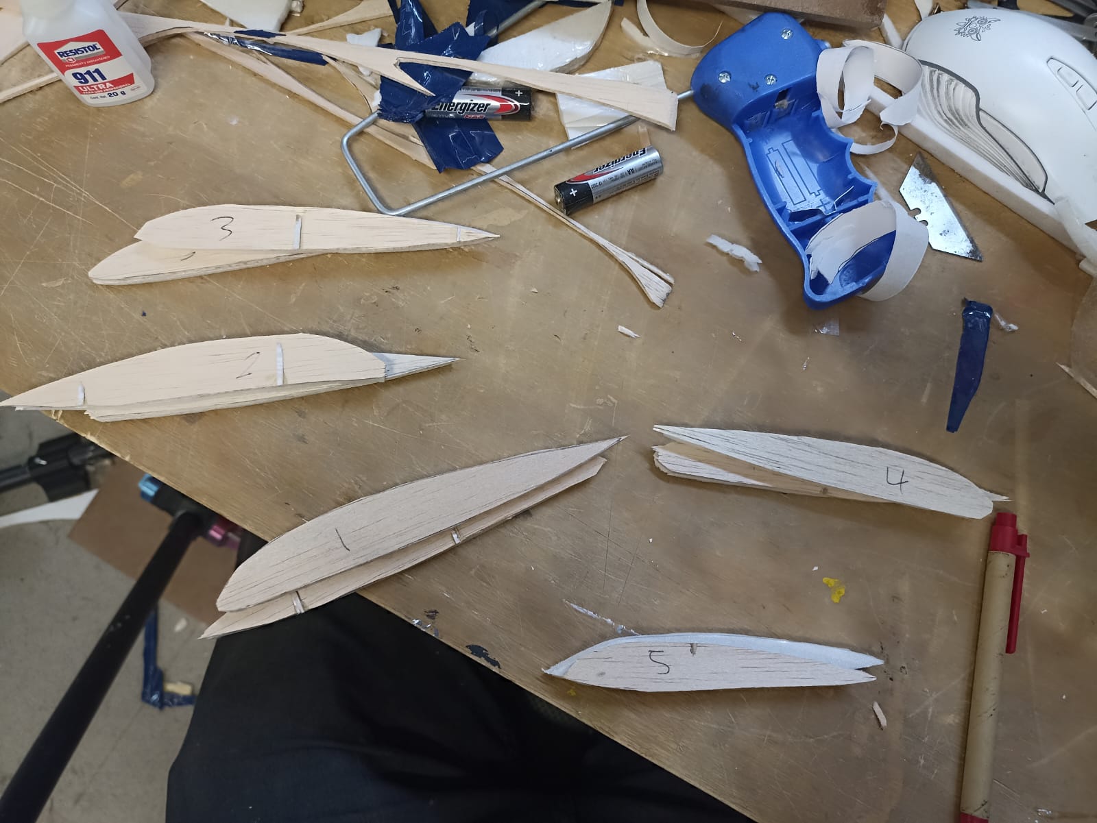
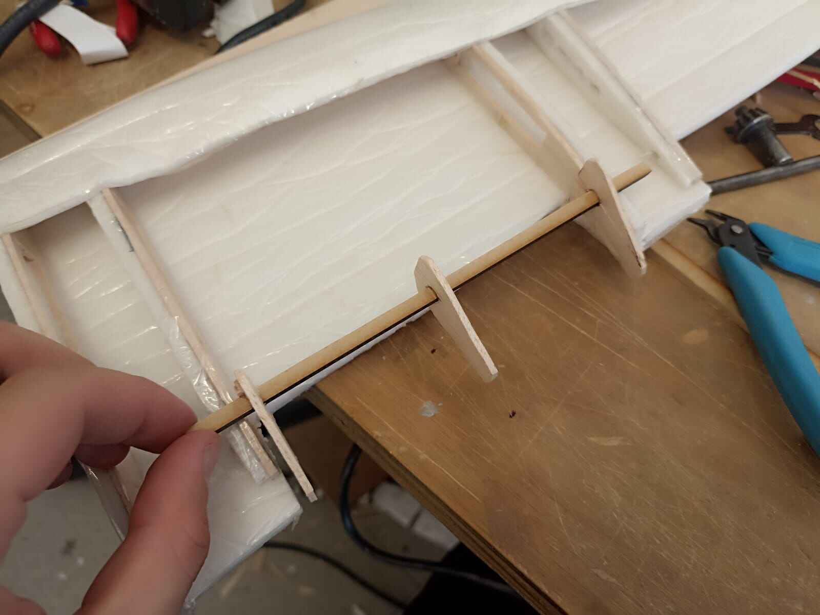
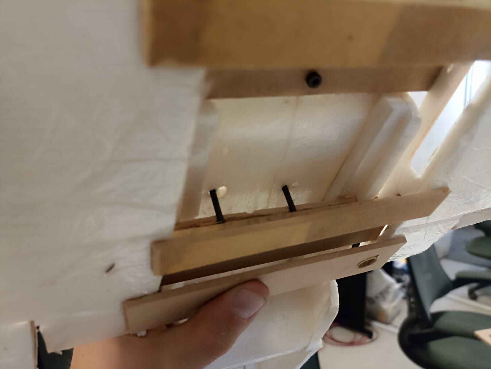
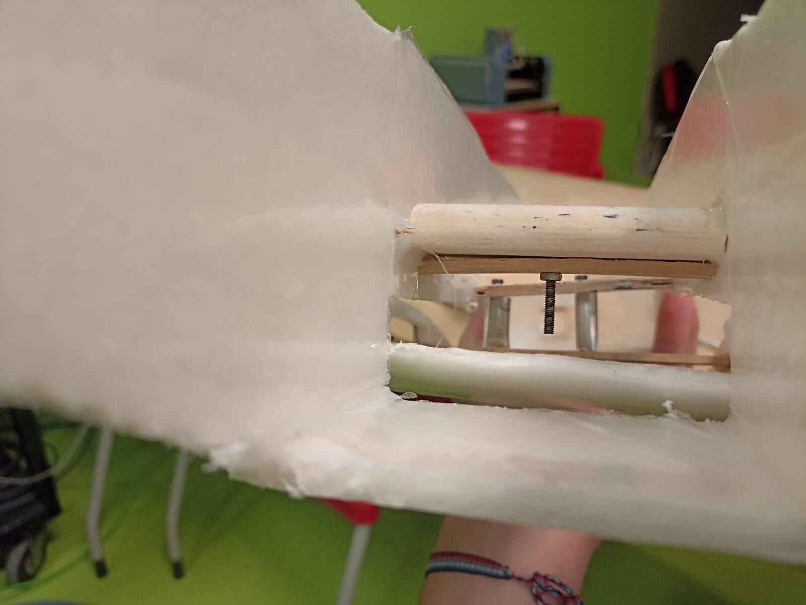
The plan for the ribs is to have 2 different segments for each wing; the aileron and the flap, so I needed to arrange the ribs so I could fit both. So I drilled a hole on the tip of the ribs to get a wooden stick through them and hold them in place.
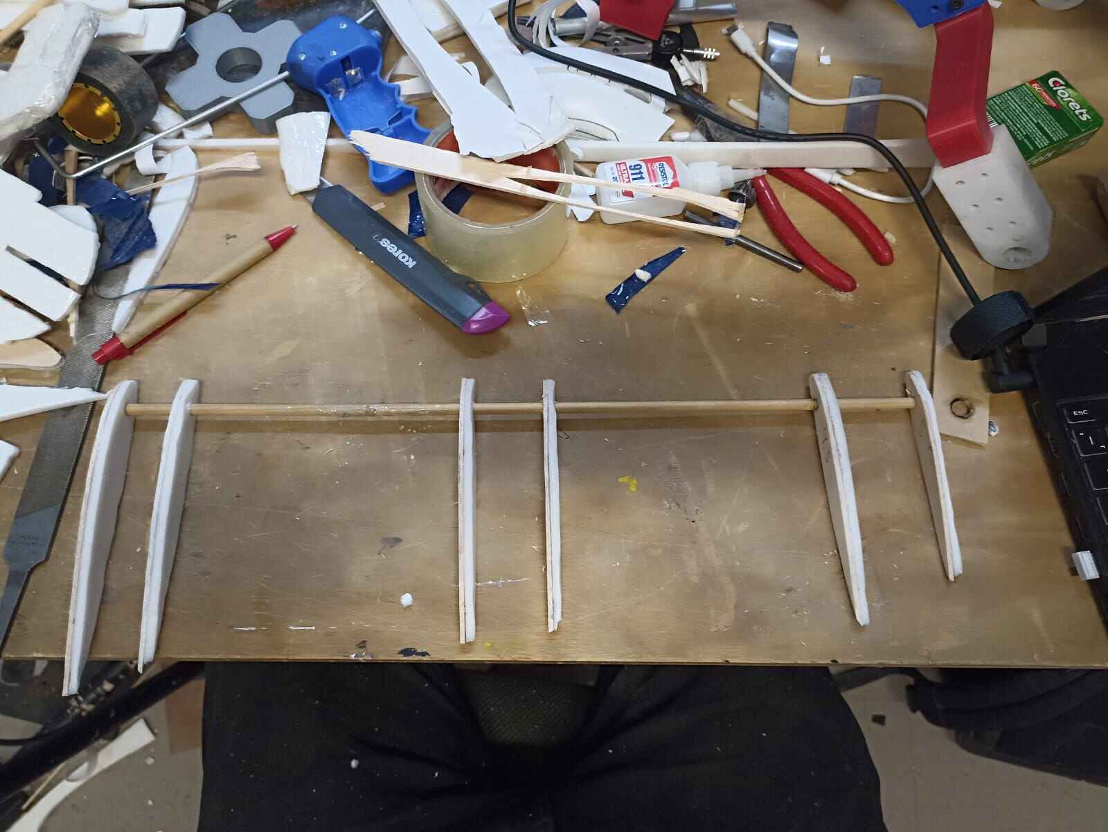
If you count, there is an extra rib I had to add so I could have 3 pairs of ribs to do the configuration I wanted to do. Also I made a rectangle inside the ribs so I could later fit the cables through the wing
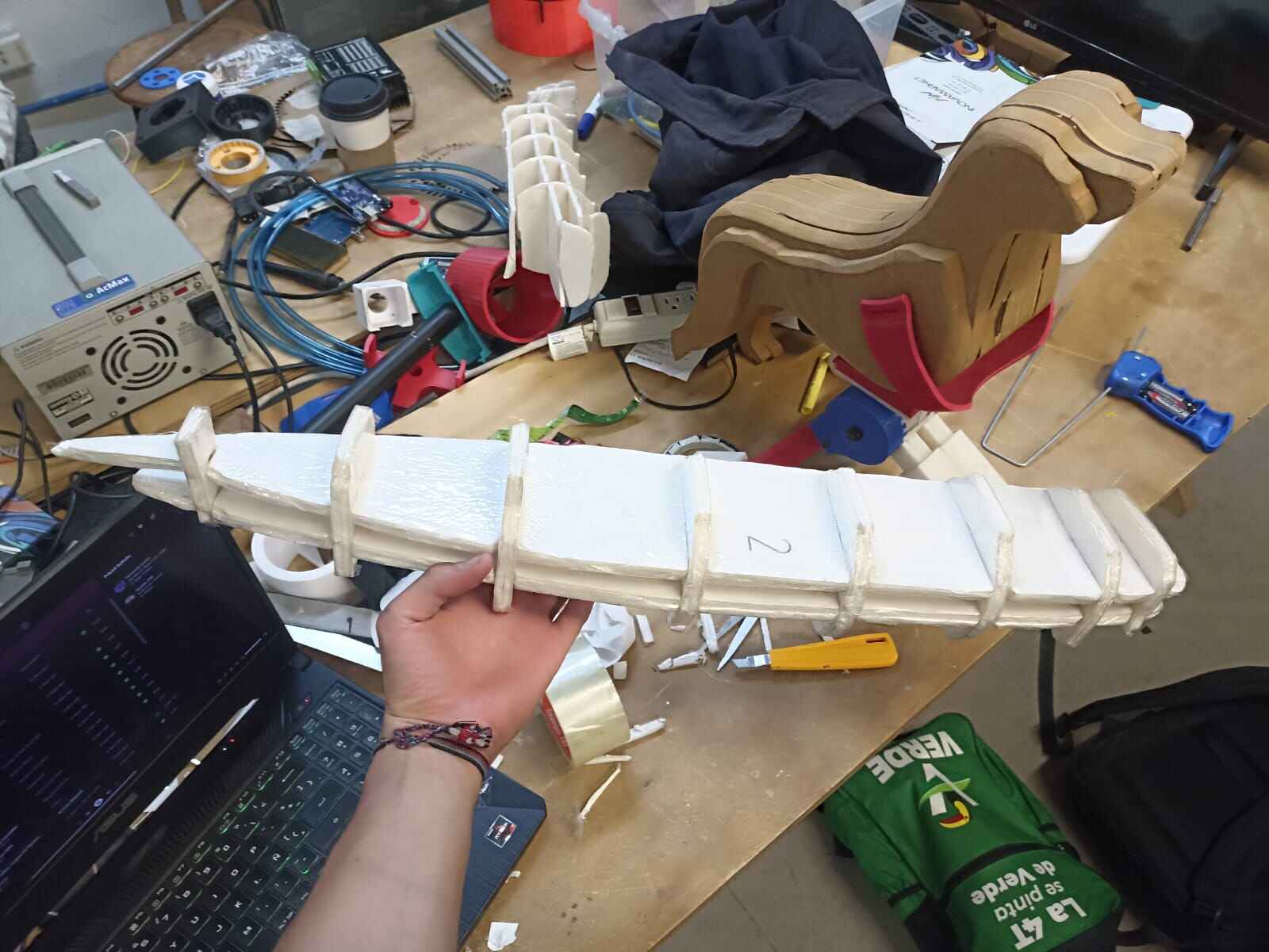
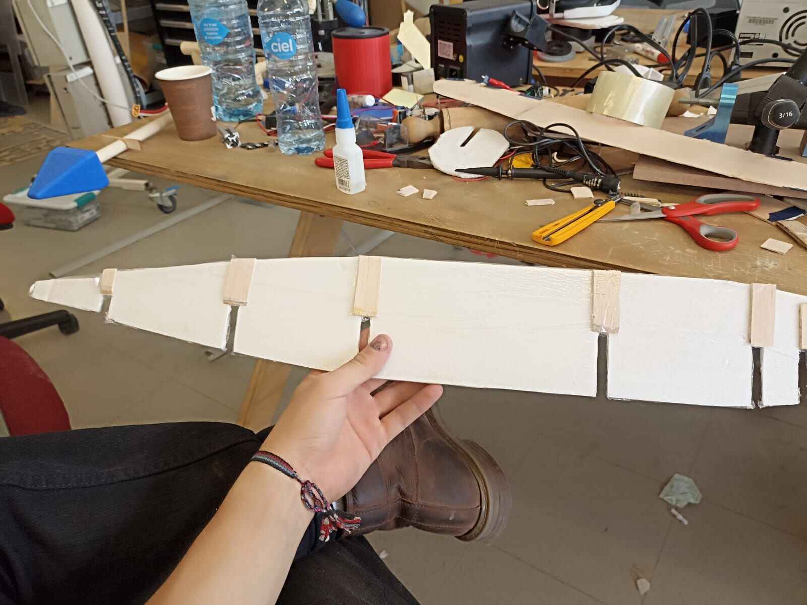
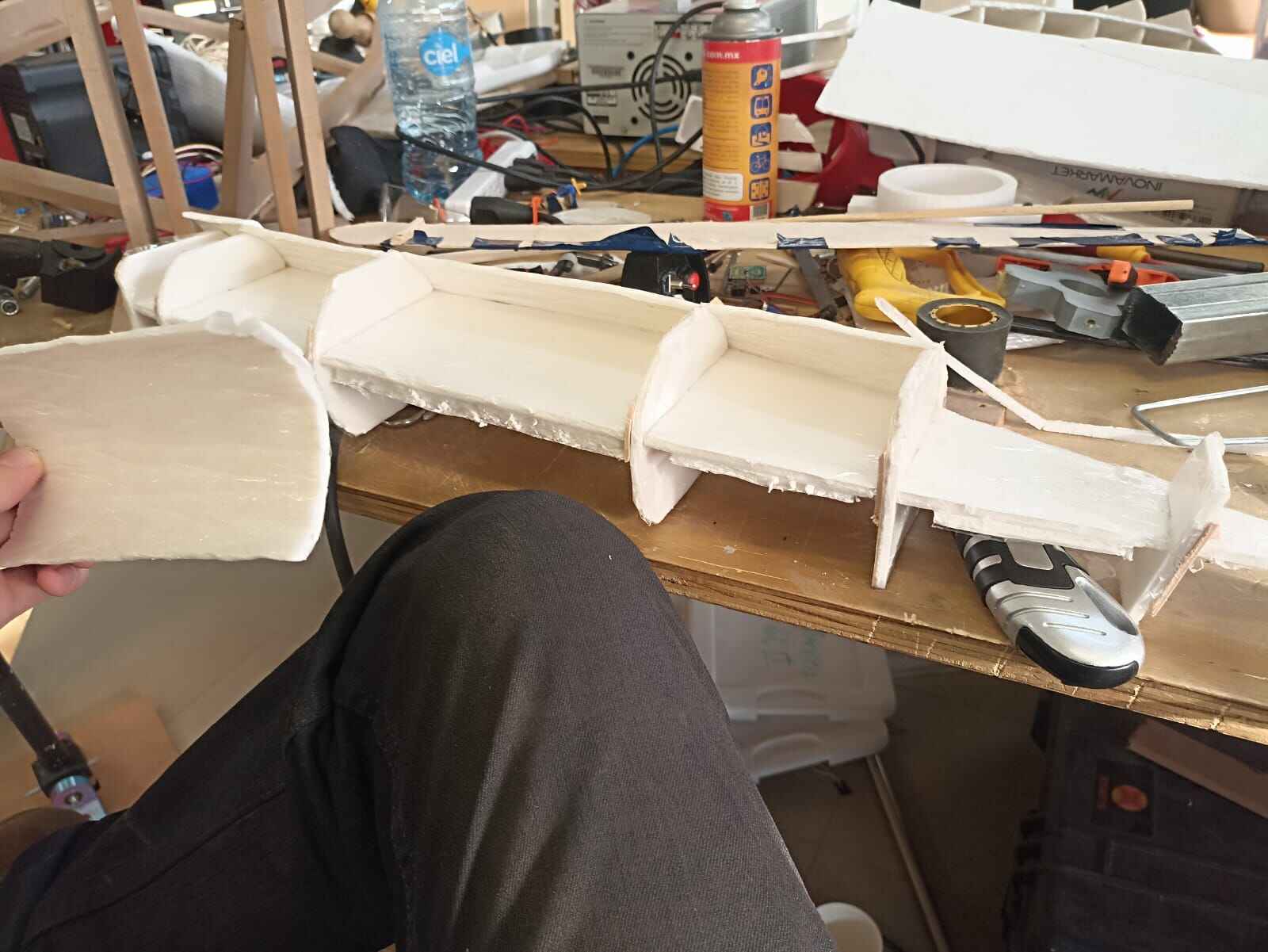
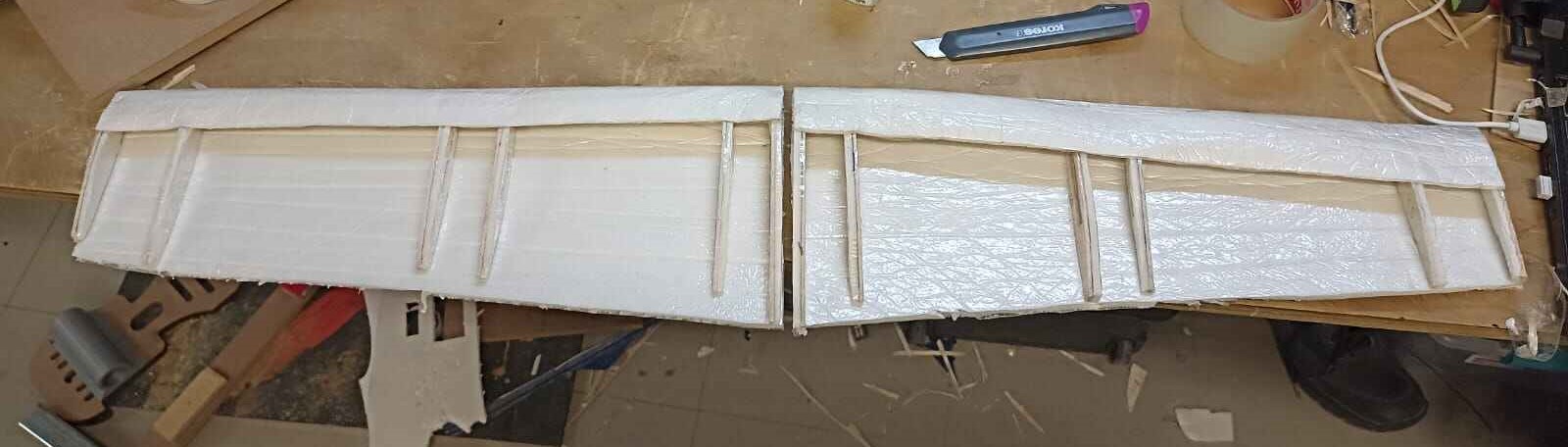
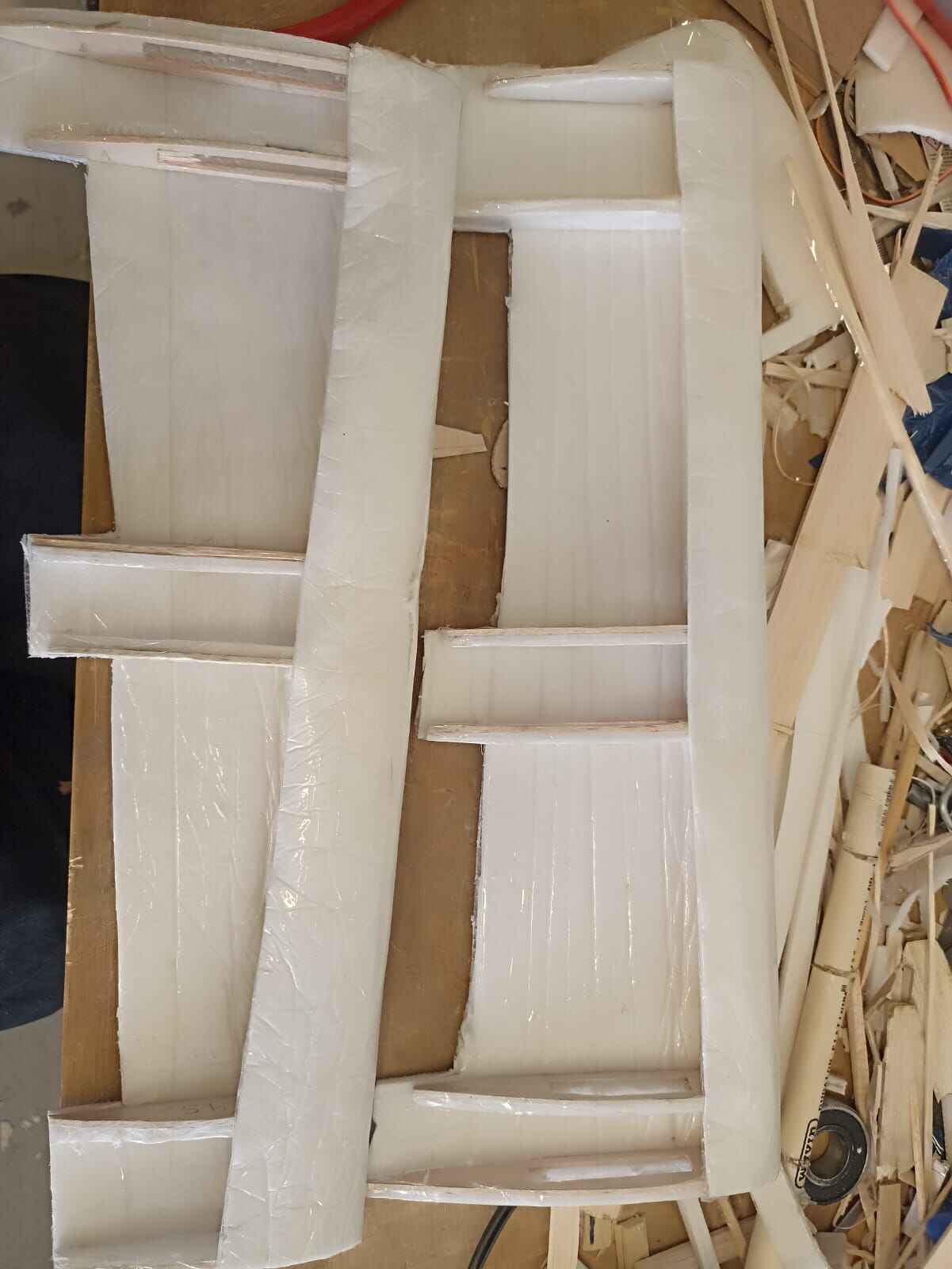
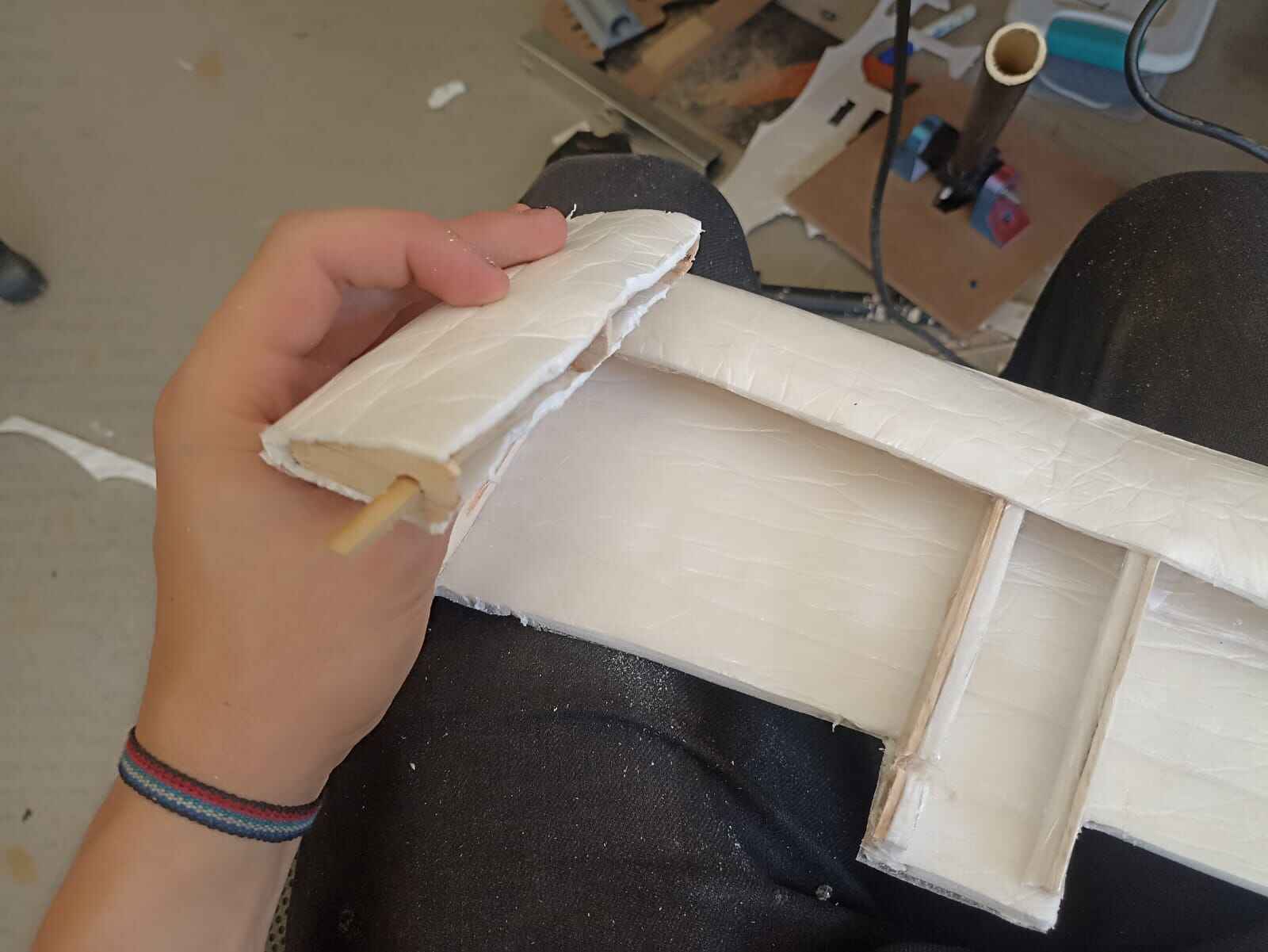
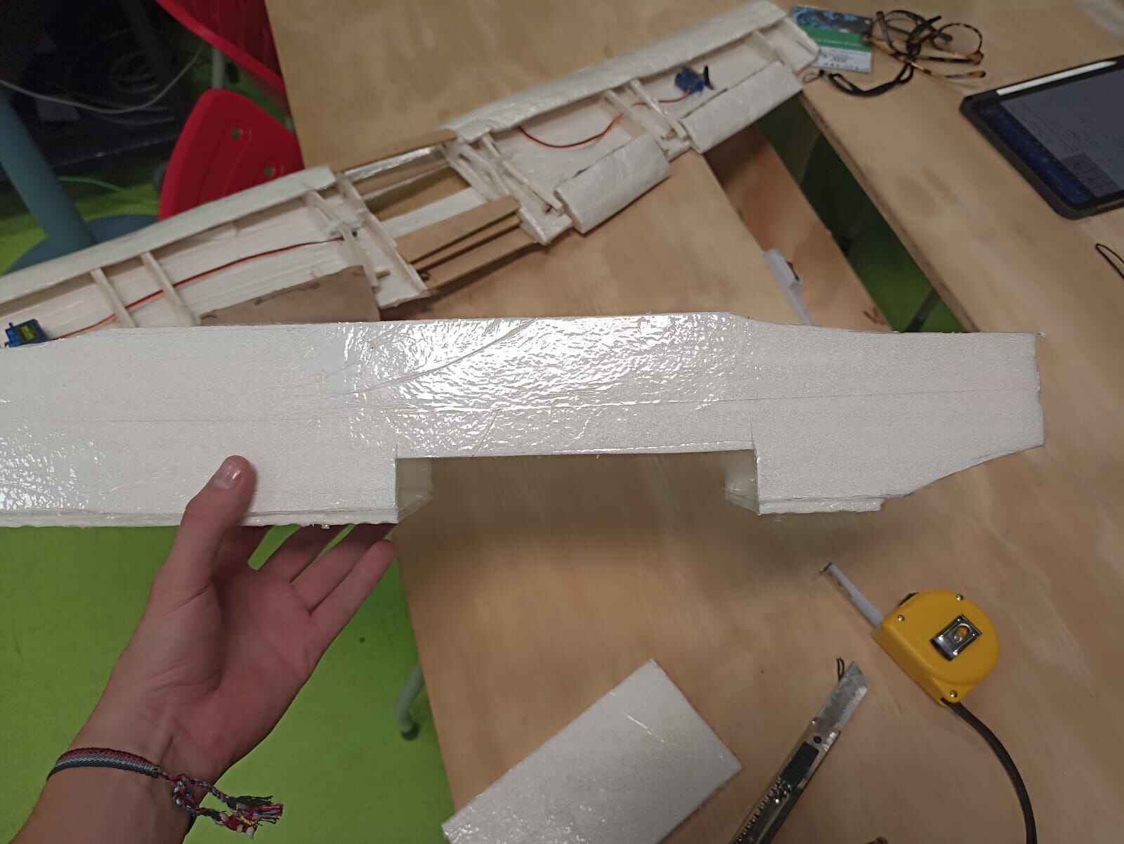
Once I have the rib structure, I measured the foam that I would have to cut to cover the botom part of the wing
Just like the other pieces, this was covered in tape and carefully bended the front part to wrap around the ribs
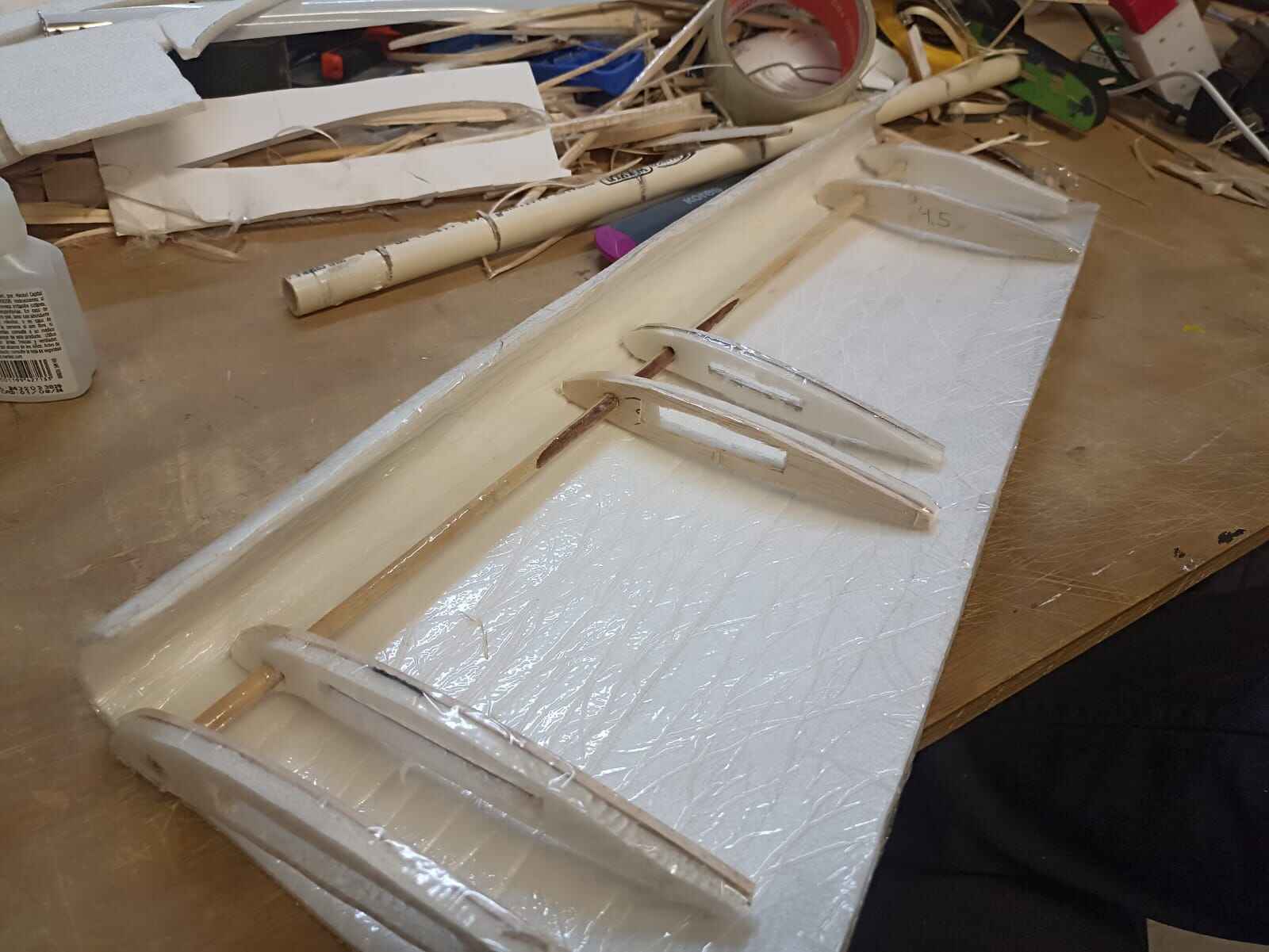
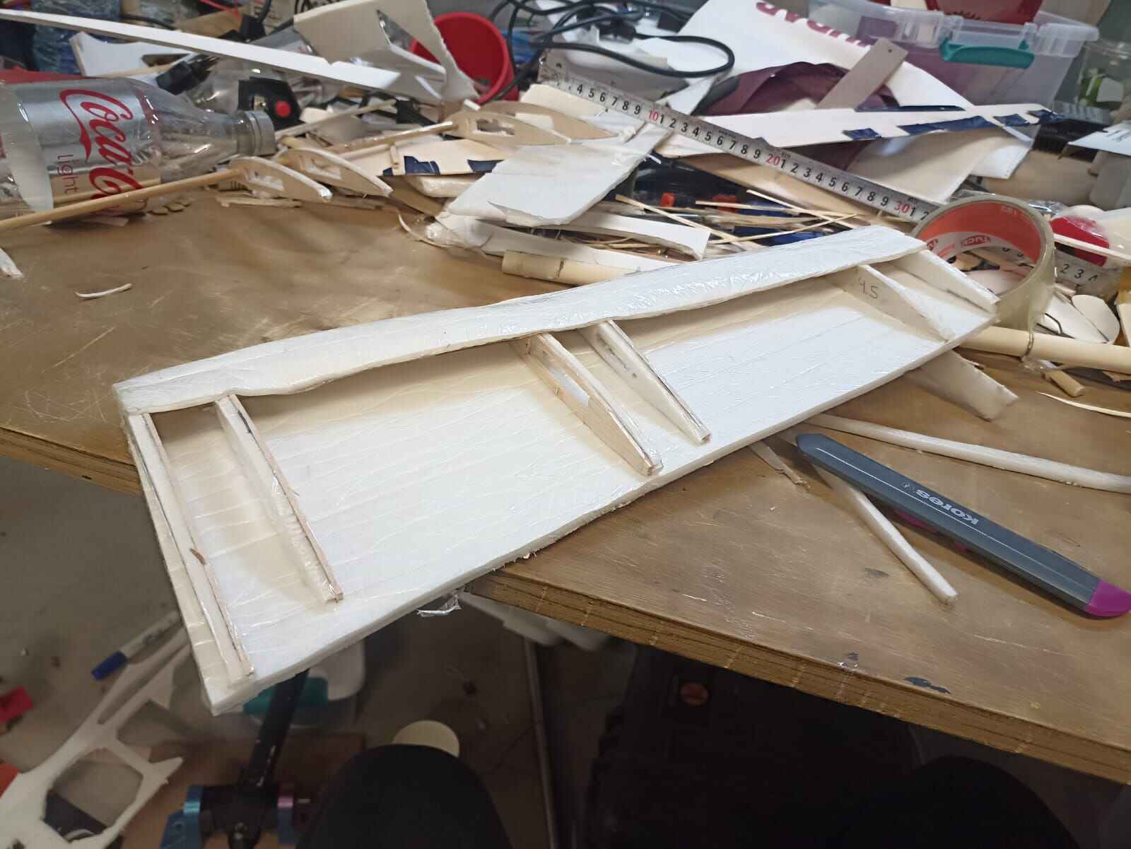
And I did the same thing to the other wing, here you can clearly see the taper I was talking about.
Now we need to make space for the ailerons and flaps, meaning we need to cut the section between the ribs to fit the rotating parts.
The flaps and ailerons should only be just a small section of the back of the wing that will rotate on a certain axis, so I drew and cut them out of foam and balsa, just like the ribs, and made holes to fit another wooden stick them
We measure the size we need them to be, and cover them in more foam
This is how the ailerons should move
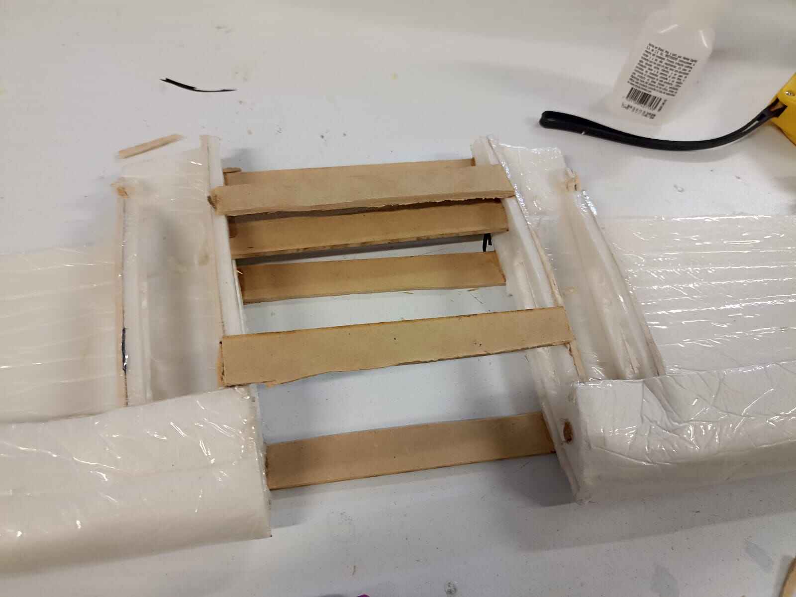
From there I decided to join both the wings with stips of 3mm MDF that I hot glued
Then I made a cut in the fuselage where the wings would go, going by approximate dimensions.
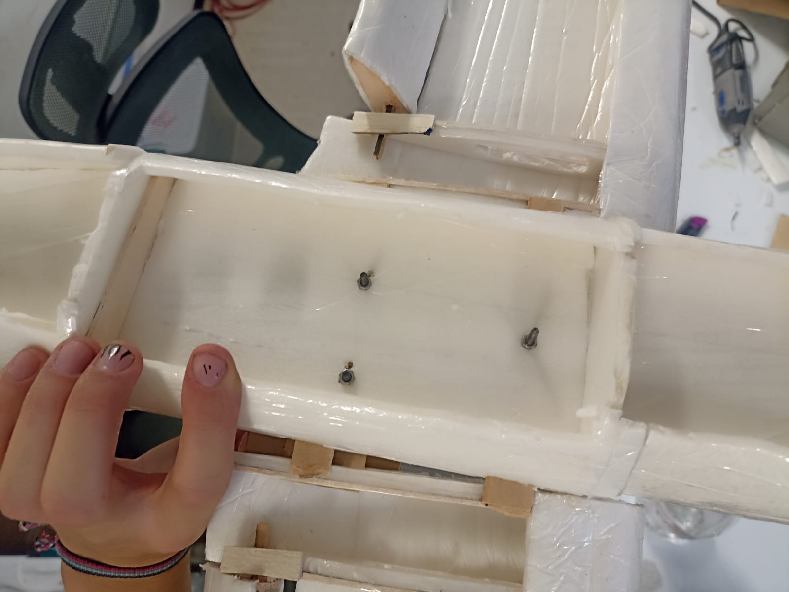
To join the wings to the fuselage, I drilled 3 holes on the MDF strips in the wing that went through the fuselage aswell. Using M3 screws and lock nuts to prevent them from unscrewing themselves, specially with vibrations from the motor.
Let´s start moving into the control systems. Pretty much all RC plane controlls are made by servomotors, they have the advantage of being lightweight, precise and has a low power consumption. The sort of geometry that make servos move control systems is by pulling and pushing a rod connected to the moving part itself, so it revolves around an axis.
I will be using SG90 micro servo, as it only weights 9 grams and has up to 1.7kg*cm of torque; more than enough for this appplication.
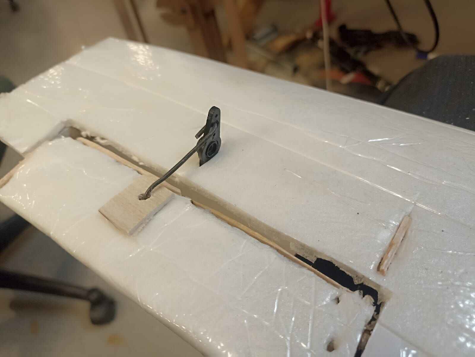
The most common way to place servos are by doing a small cut so the control horn sticks out and is attached to the aileron by a rigid piece of wire
To test the functionality of this setup, I wired the servo to an Arduino and made it move around 50° degrees, it worked suprisingly good
Second fuselage prototype
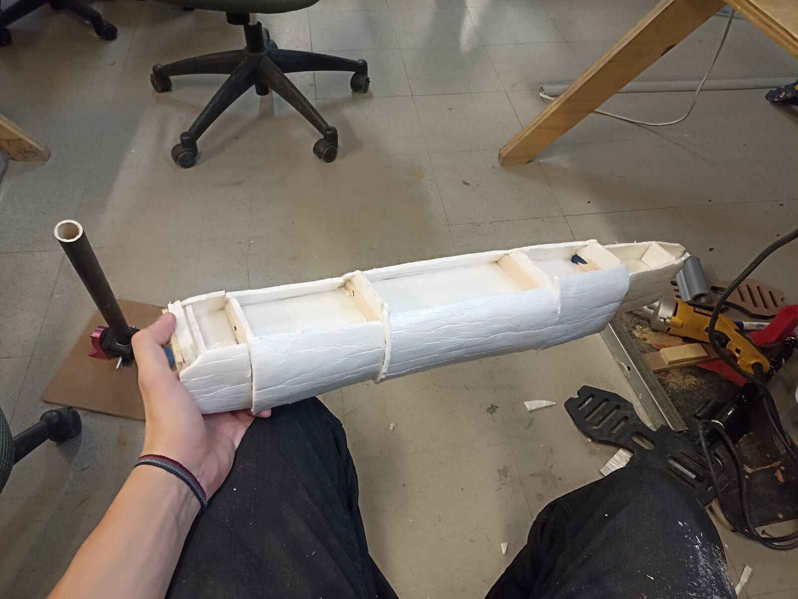
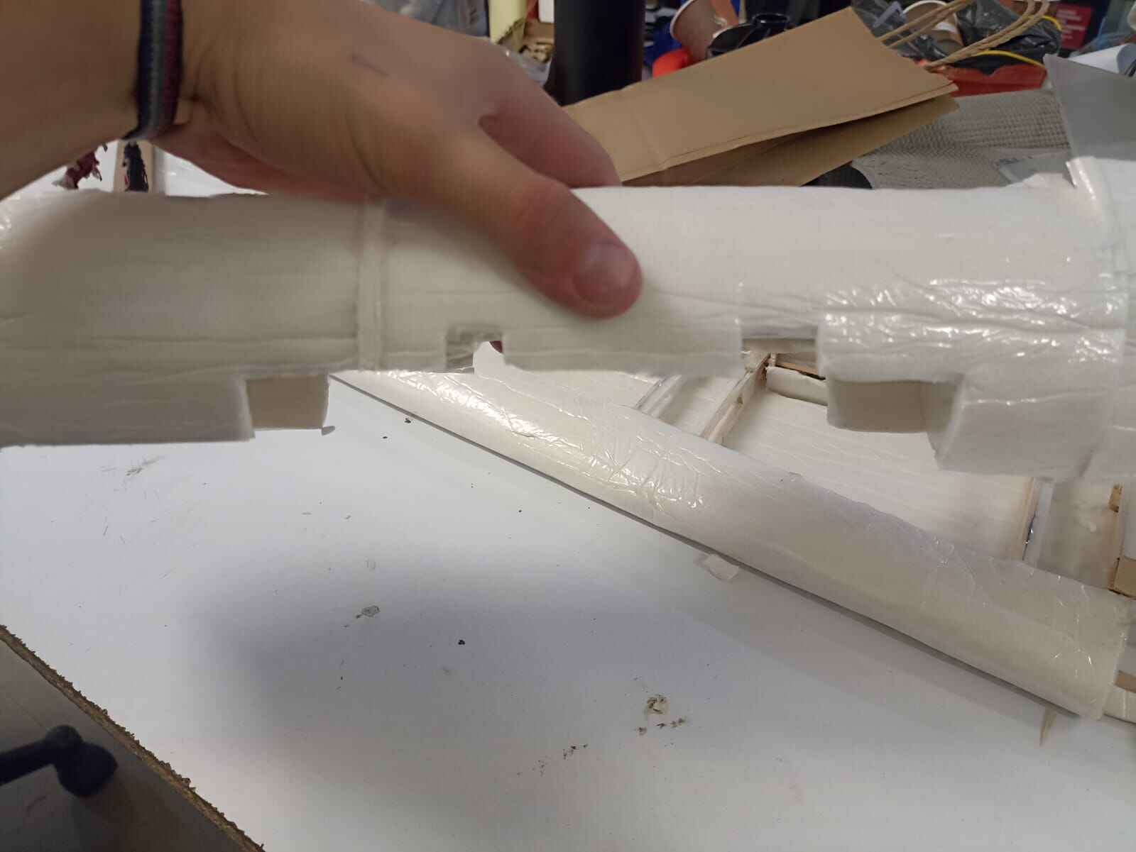
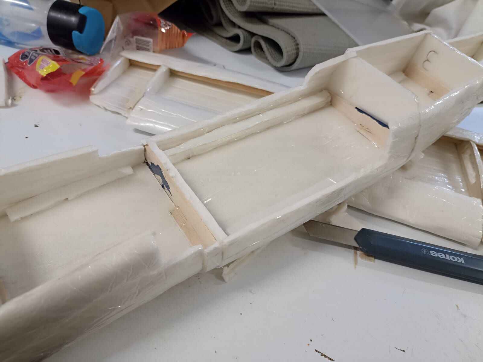
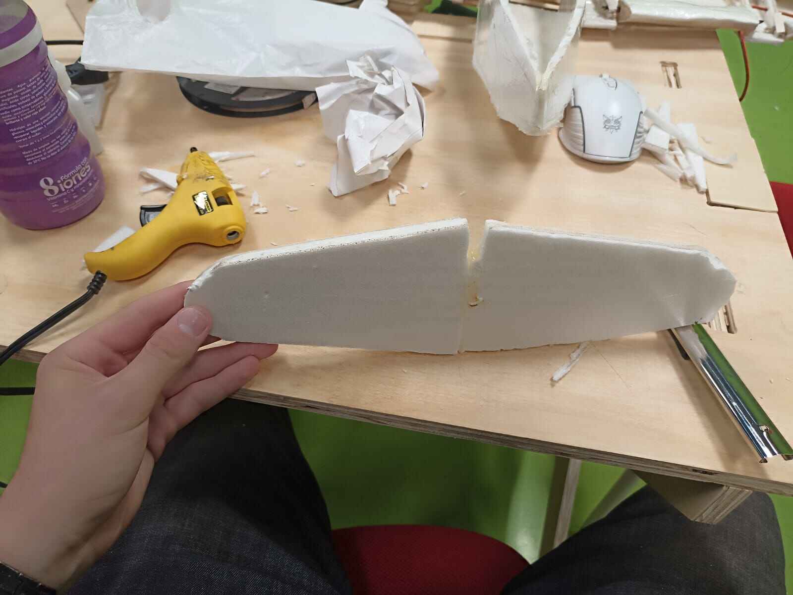
So, after leaving the fusleage in a classroom overnight, someone decided it was brilliant idea to place a box full of metal on top my fuselage. Needless to say it broke beyond repair. The wings were recoverable but I had to start again. This time, I wanted to simplify the design but doing a simple yet durable rectangle fuselage made only with straight pieces of foam.
To hold them togther, I used hot glue since I saw it was a very effective way of holding foam pieces together, after pasting them I cutted a preliminary outline of the plane´s shape.
Also made a cut for the wings
I attached the fuselage and wings the same way
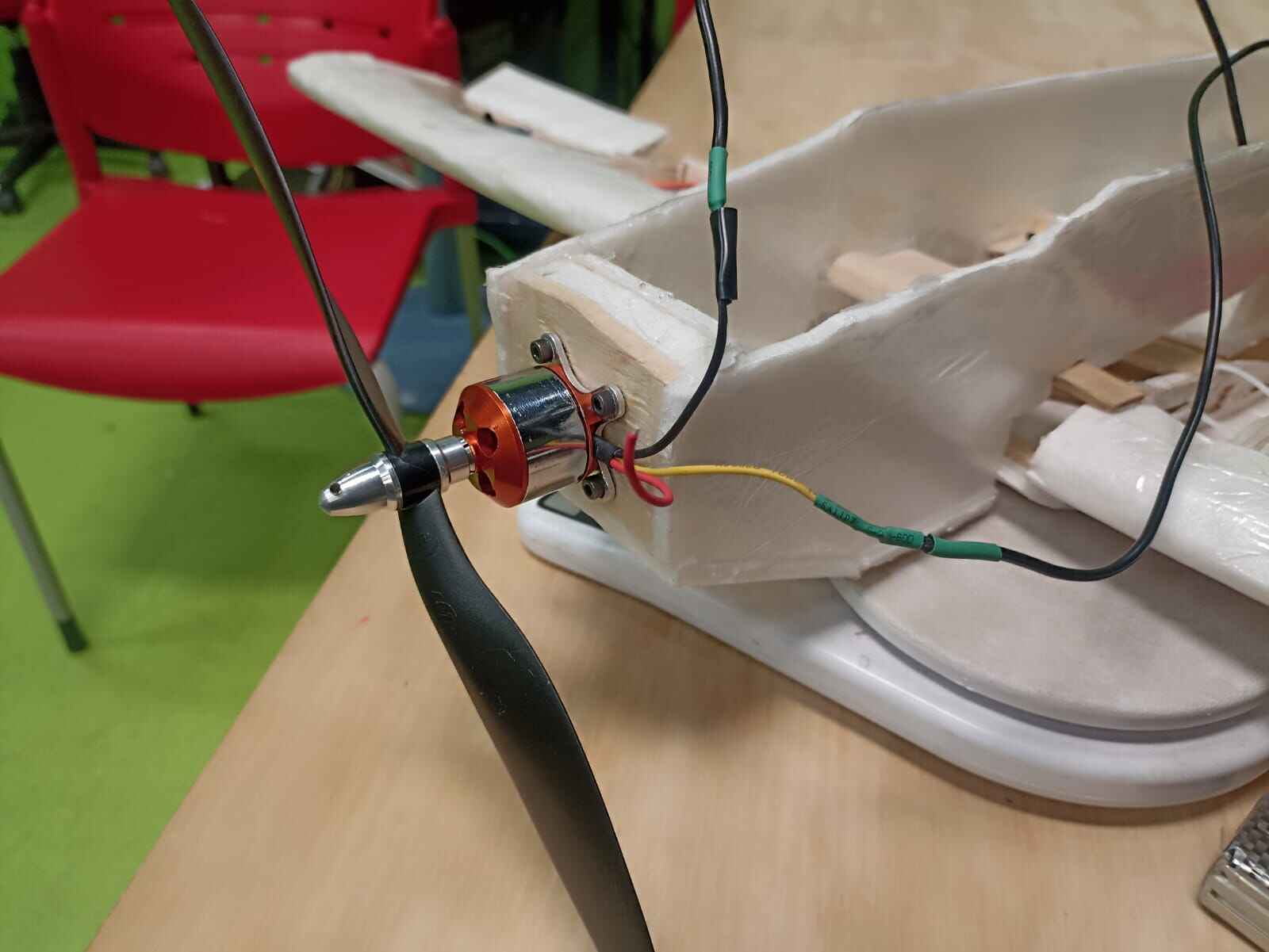
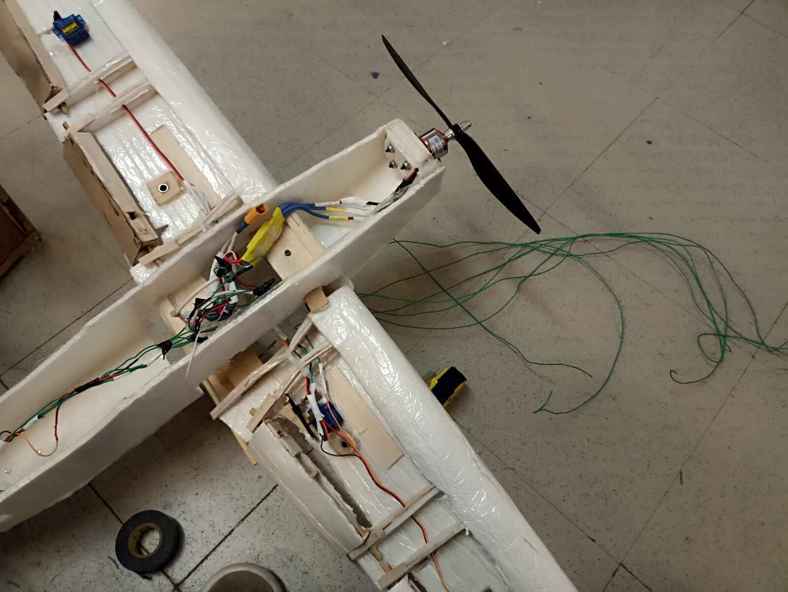
For the motor, I used the A2212 1000KV brushless motor, which I worked with on the Output Devices Week. I drilled 4 holes on the front part of the fuselage and attached the motor with M3 screws and lock nuts aswell.
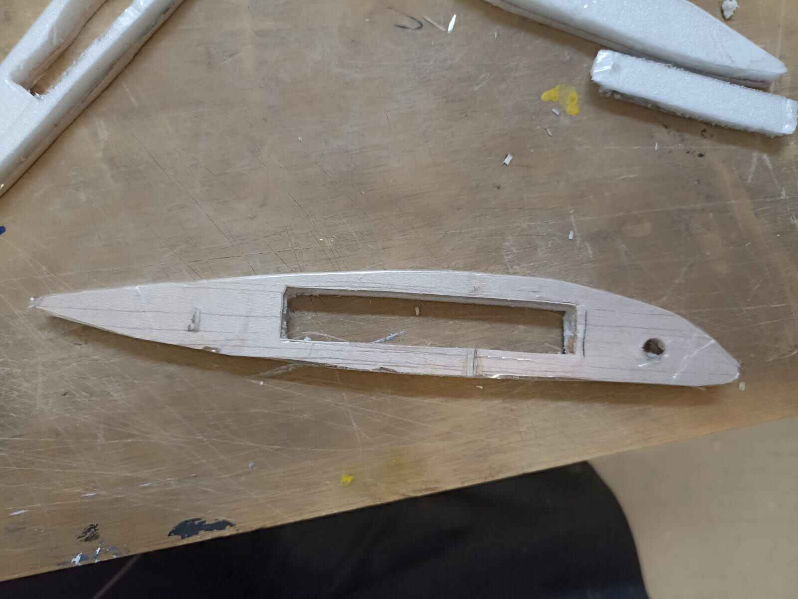
Let´s move to the tail part, where I did the elevator part on the laser cutter. The design came out of the 3D model I designed
I also made an outline for the rudder out of balsa, along with the rudder itself.
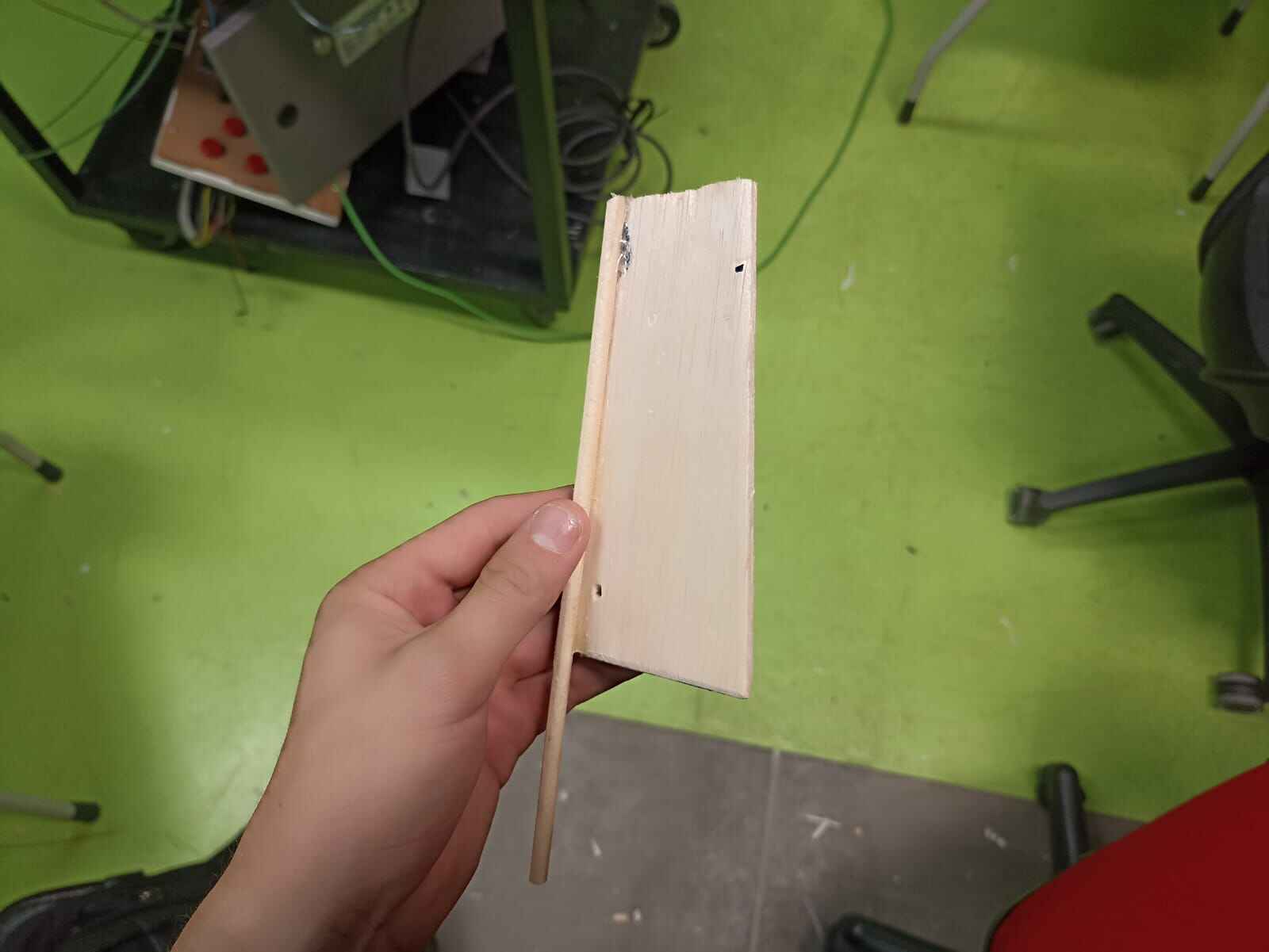
I made a cut in the elevator to have a fixed part attached to the fuselage, and another mobile one that was attached to a servo directly to make it move
I also atttached a servo directly to the rudder to make it spin
And finally for the flaps, I linked them both with a wooden stick to make them rotate at the same angle using the same technique that I did with the ailerons
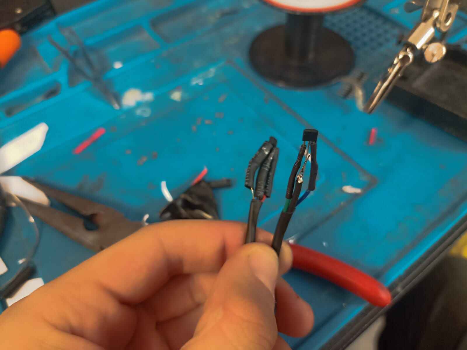
After adding all the servos, I had a bunch of cables inside the airplane. So what I did the following: join all the voltage wires together, all the ground wires together, and left the signal ones individually to be connected to the microcontroller.
Here is a quick timelapse of me soldering some of the cables together :)
This will later be connected in the assembly
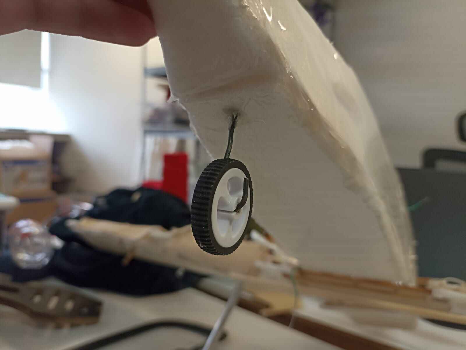
To temporarly finish the aircraft, I decided to add a simple landing gear so the plane could stay up by itself.
The back wheel is just a little toy tire attached with the same wire I used for the servo mechanisms.
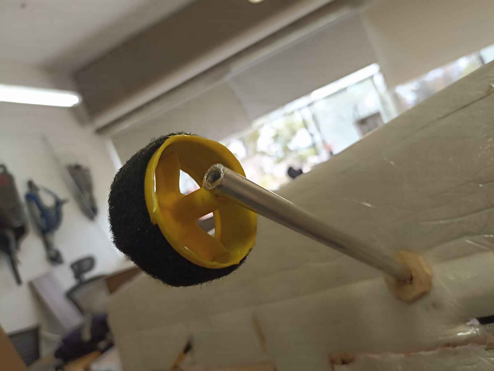
For the front wheel, i took 2 plastic tires used for robots here at Ibero, and drilled a hole through a lightweight aluminum rod, and fitted a bolt through it, holding it in place but allowing it to rotate freely.
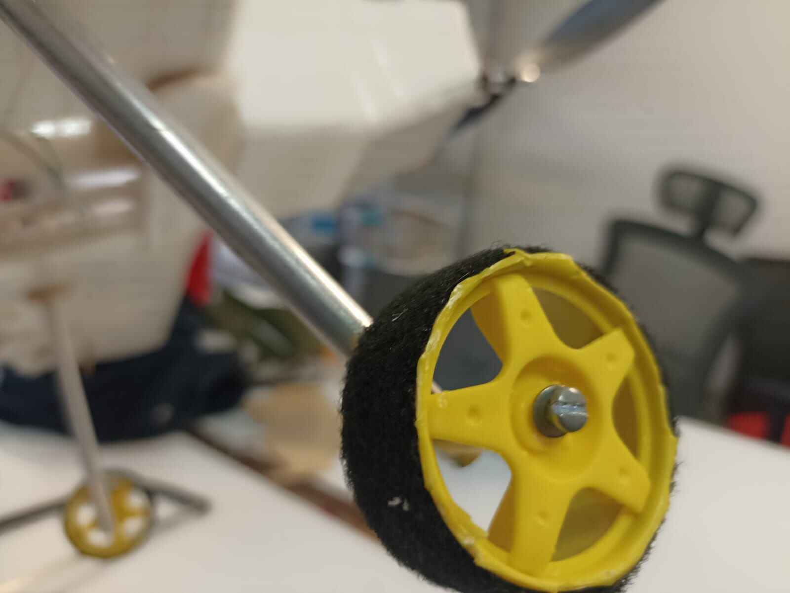
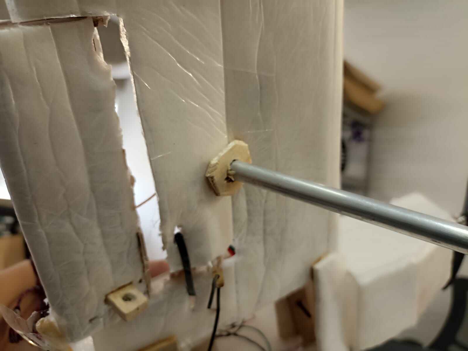
I attached them to the wing by perforating a small hole to get the aluminum rod through it, and using hot glue and balsa wood to hold it in place.
Controls
The simulated controls are divided into 3 different segments: throttle/flaps, center stick and rudder pedals. Altogether they make the basics to control a simple RC plane. As I did with the airplane, I first designed everything in Solidworks to make sure everything made sense and had accurate measurements.
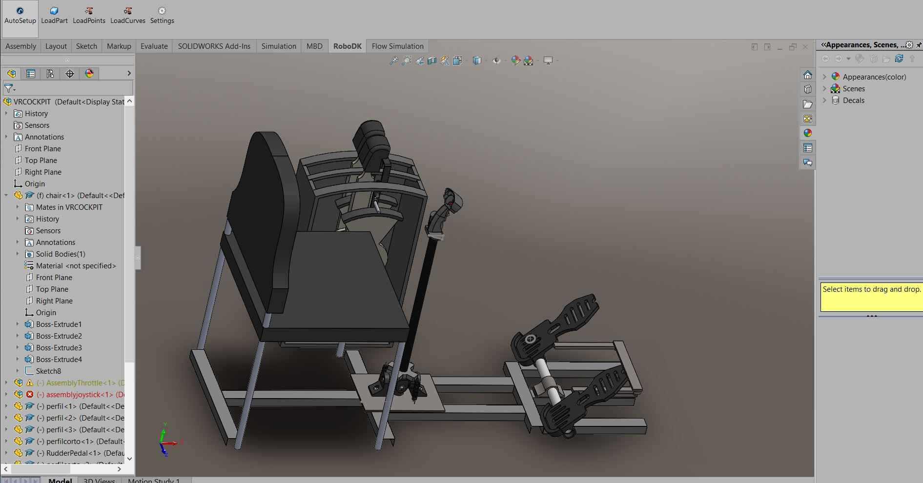
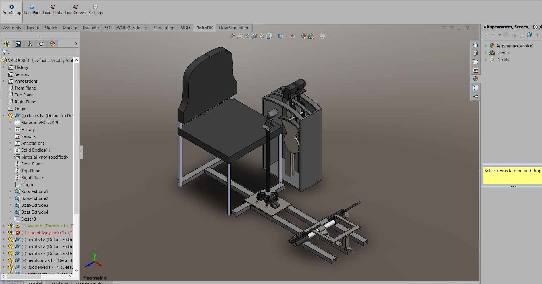
Most measurements I took based off the chair height modeled, which is a copy I made from a chair we have here at the lab. This way I could measure the height of the control stick, height of the side controls and the distance to the pedals
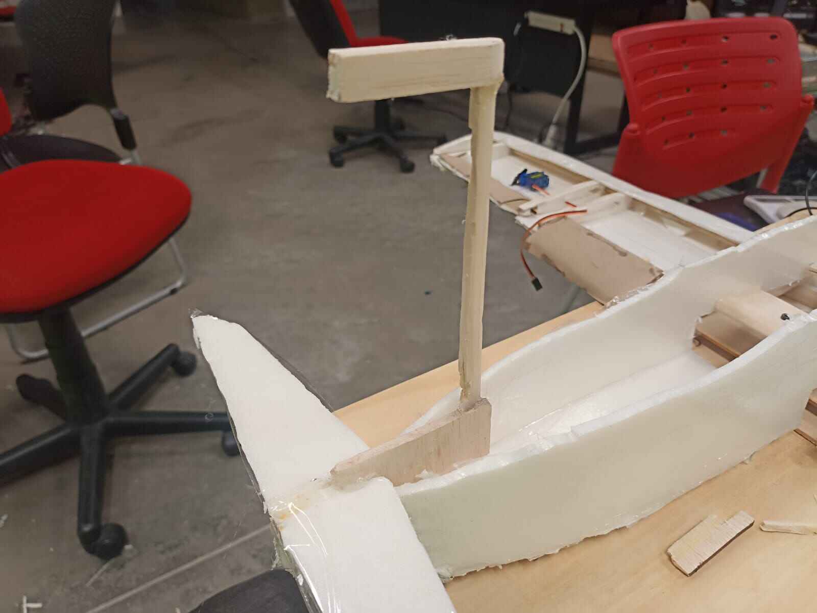
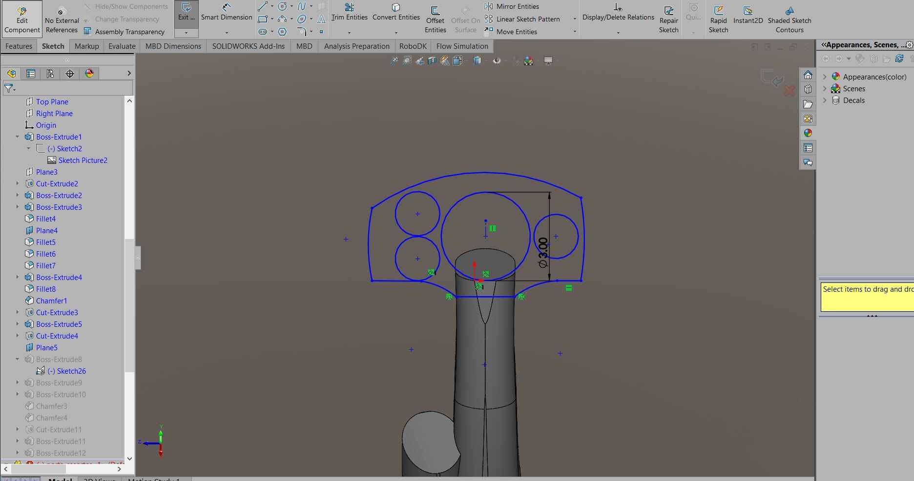
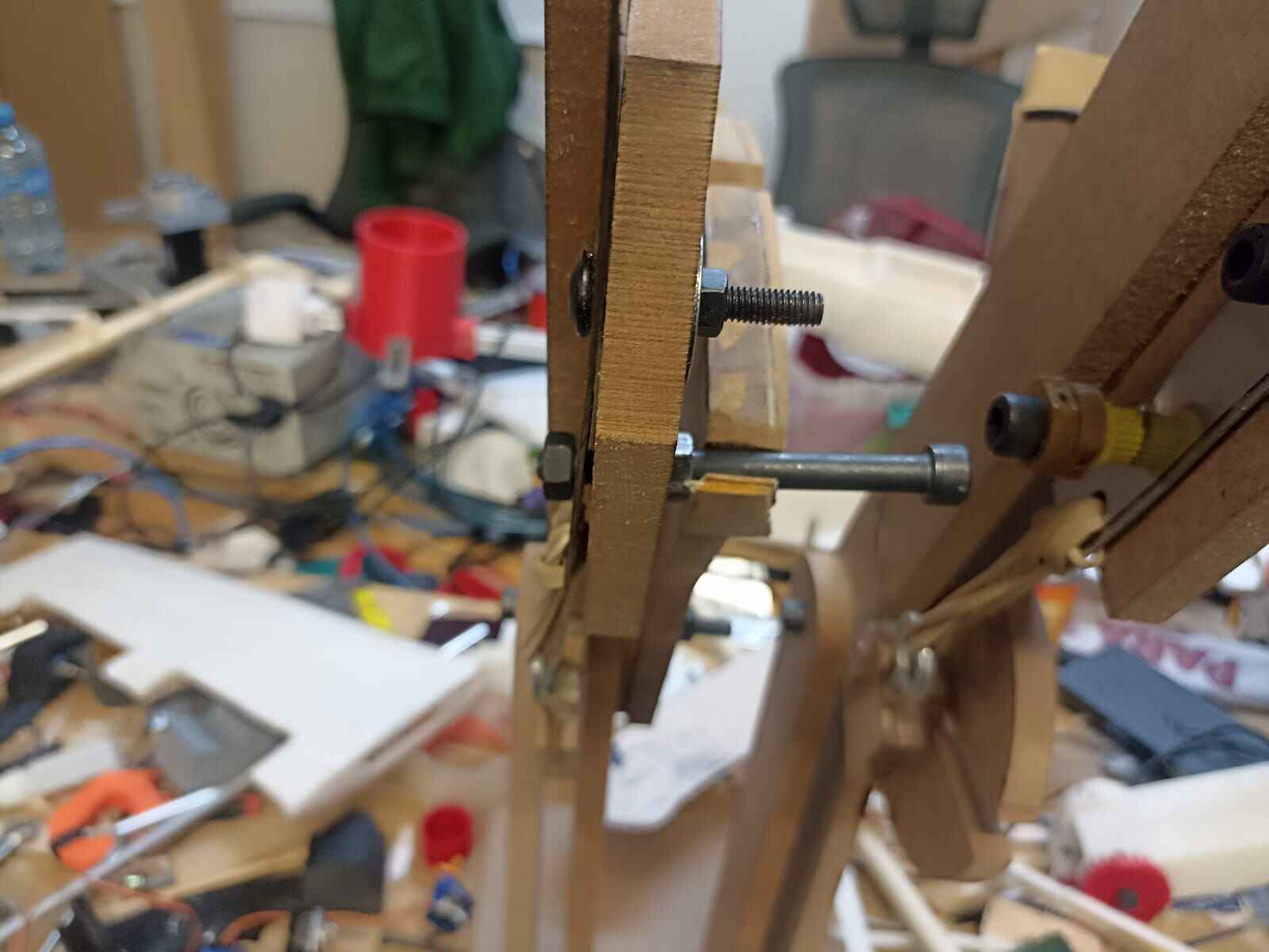
Let´s start with the bottom part of the control stick.
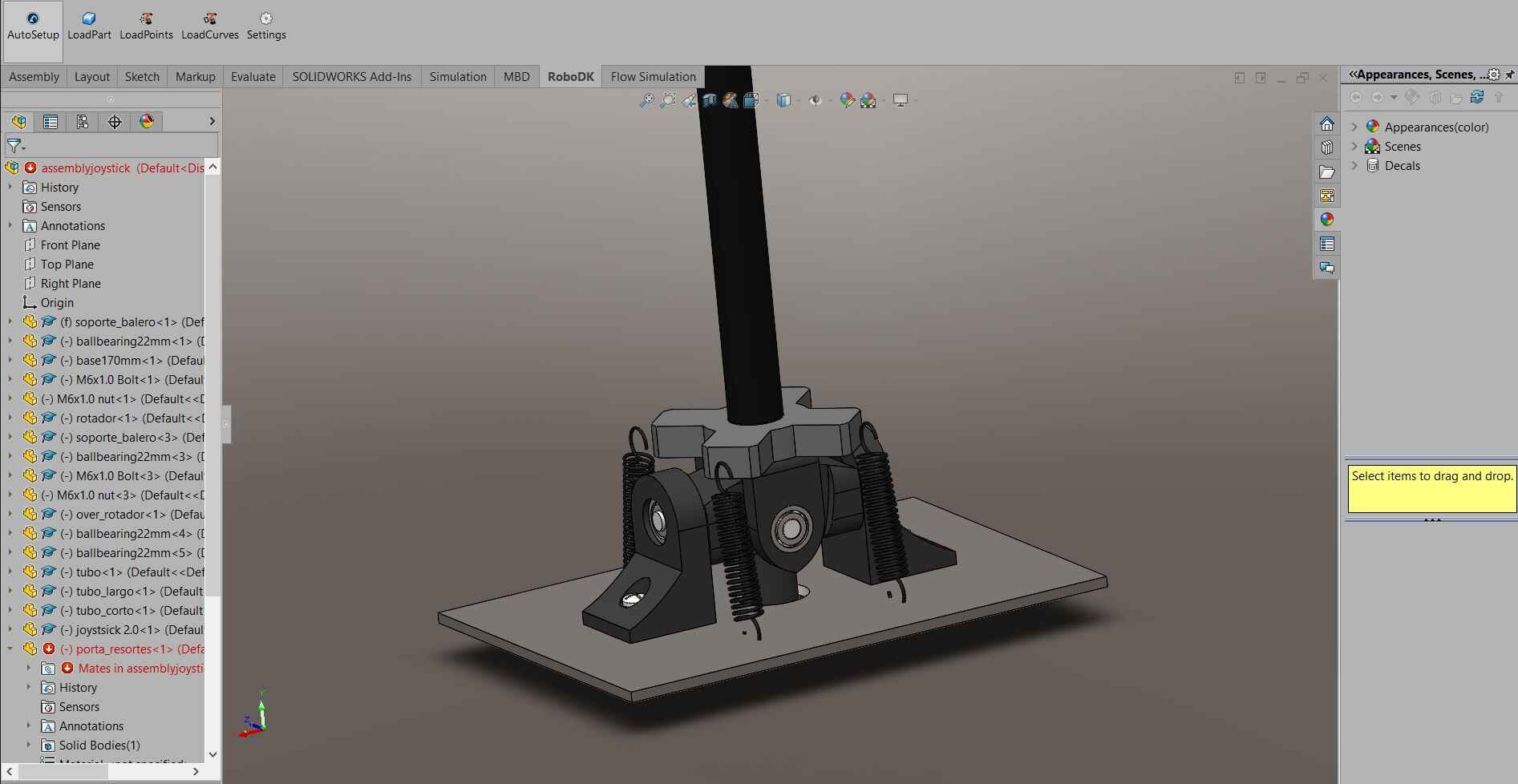
They consist of 5 main pieces, 2 side pieces at each side with hole to fit a ball bearing, which holds a rod that goes through the center rotator, allowing it to rotate freely in one axis
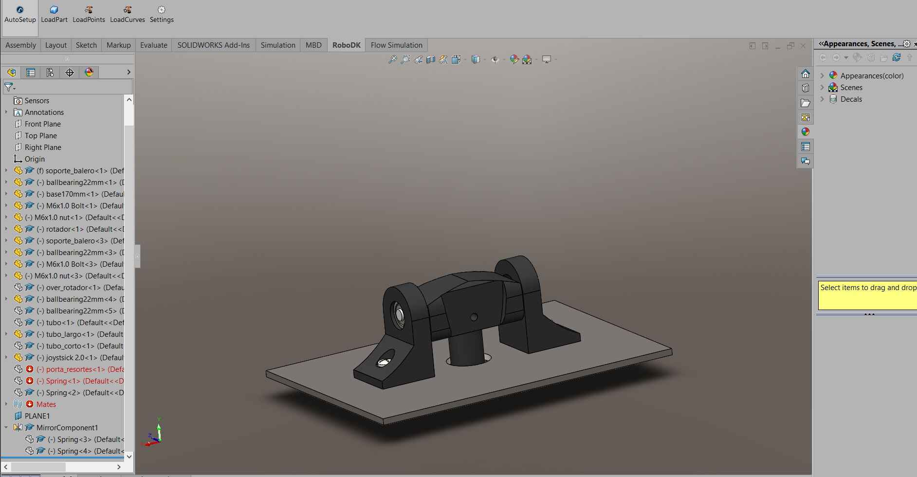
The rod at the bottom going through the hole is to limit the distance the rotator can move, but we´ll get to that later.
The forth piece is a another rotating piece that swings in the other axis. It also has a rod going through the center rotator that is held by ball bearings on the extremes
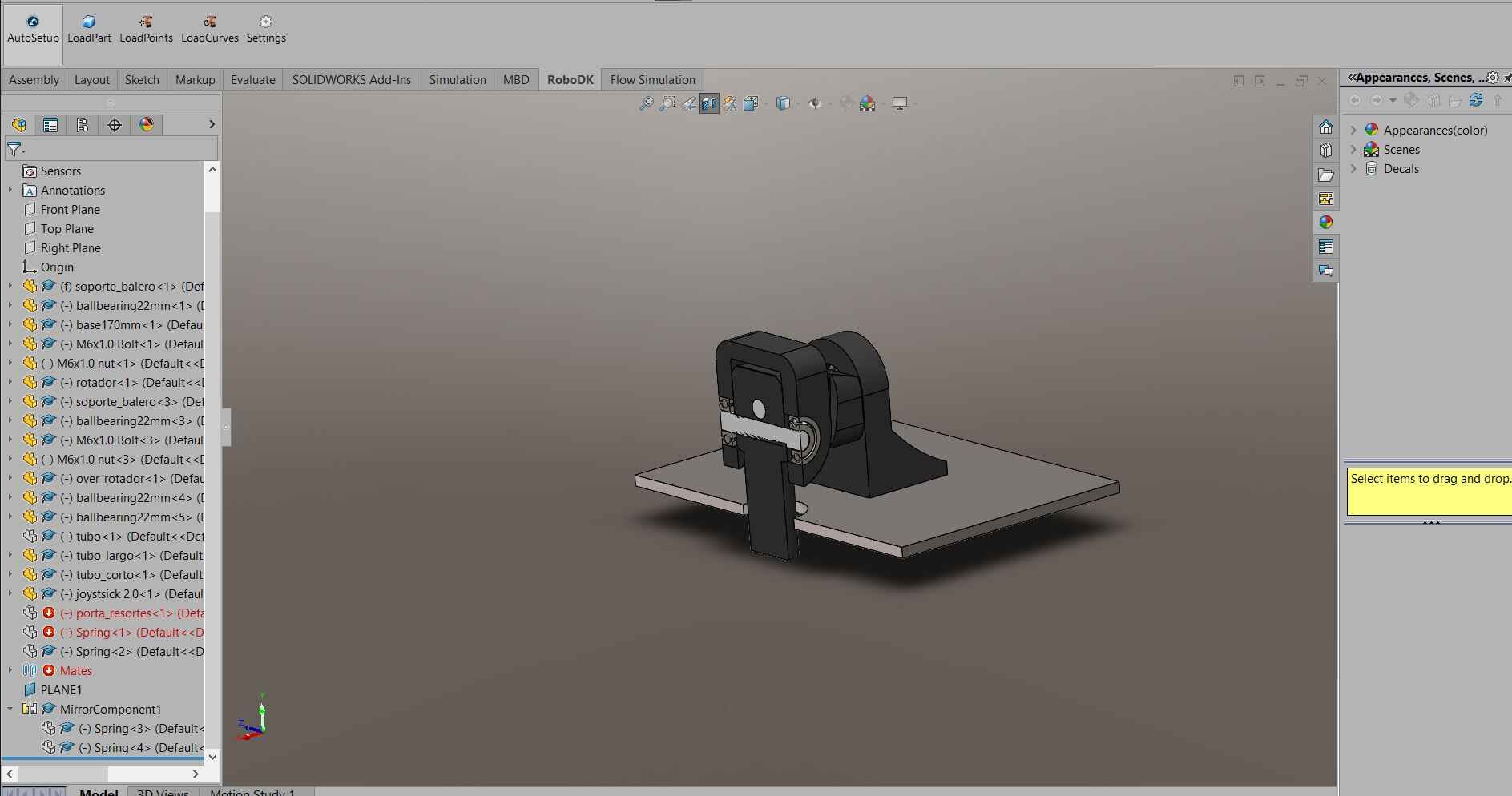
This itself creates the mechanism that allows the stick to rotate freely around 2 axis up to a certain distance.
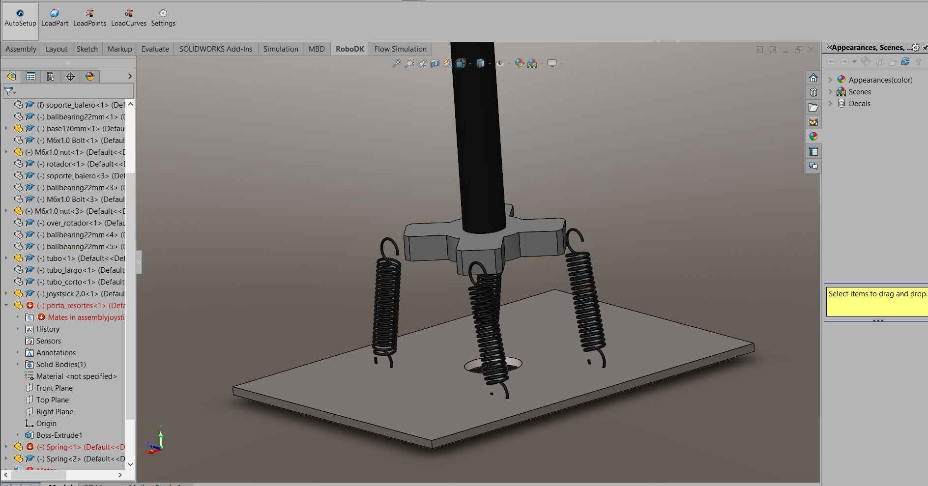
Finally the last piece will attach the springs (or rubber bands, or whatever other mechanical resisistive element you can think off) to the baseplate. This is done with the purpose of creating a realistic force feedback that pushes the stick back to the center when it moves, it will also bounce back the stick back to the center when being let go. Most, if not all plane controls have this feature that allows the pilot to better understand the forces actuating on their aircraft. All this will be connected to a 1 inch PVC pipe that will go up to the joystick.
The joystick on top will allow the pilot to hold and steer the control stick, and has additional buttons and switches that interact with the aicraft.
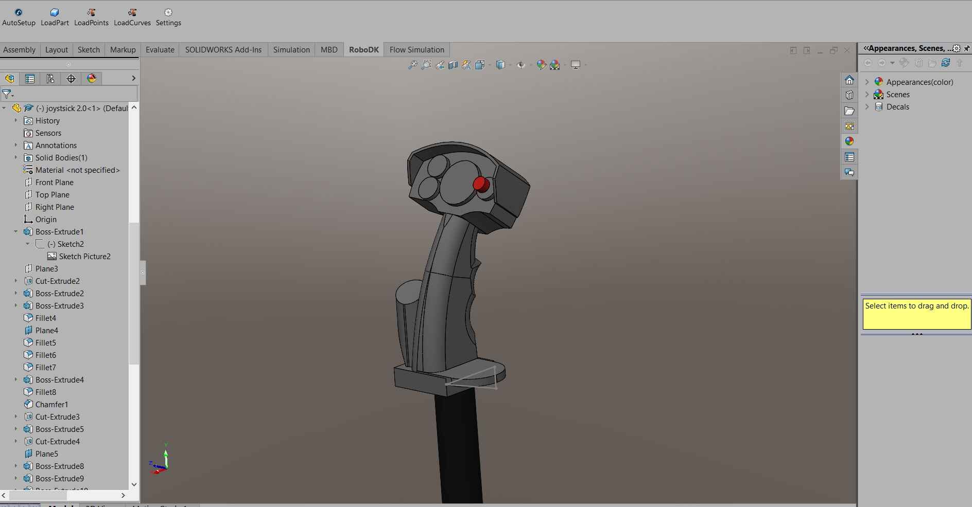
I based myself on a real fighter plane throttle for the shape and dimensions
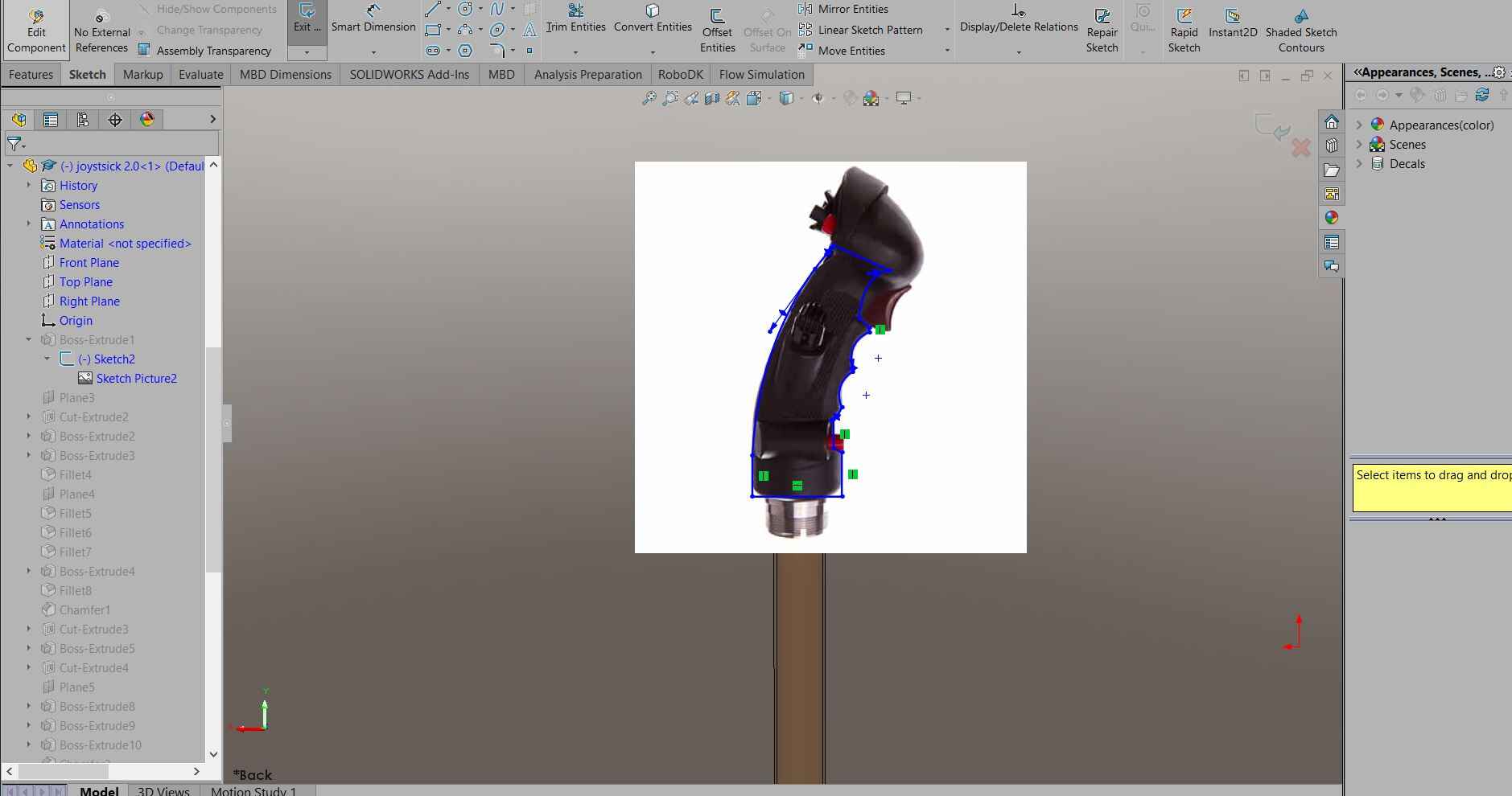
But I mostly hand build the joystick on whatever I thought would be cool. As you can see I left spaces for buttons and switches or whatever I wanted to add in the future
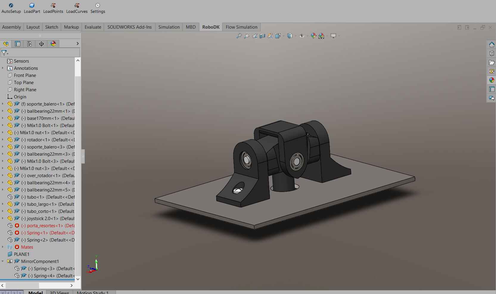
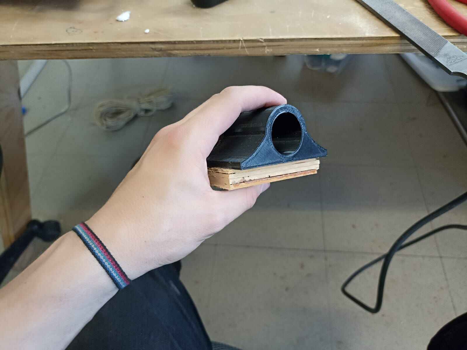
All this individual pieces I 3D printed on PLA. And also decided to paint them black with paint spray since they where different colors, except for the ball bearing holders, the colors are just to pretty...
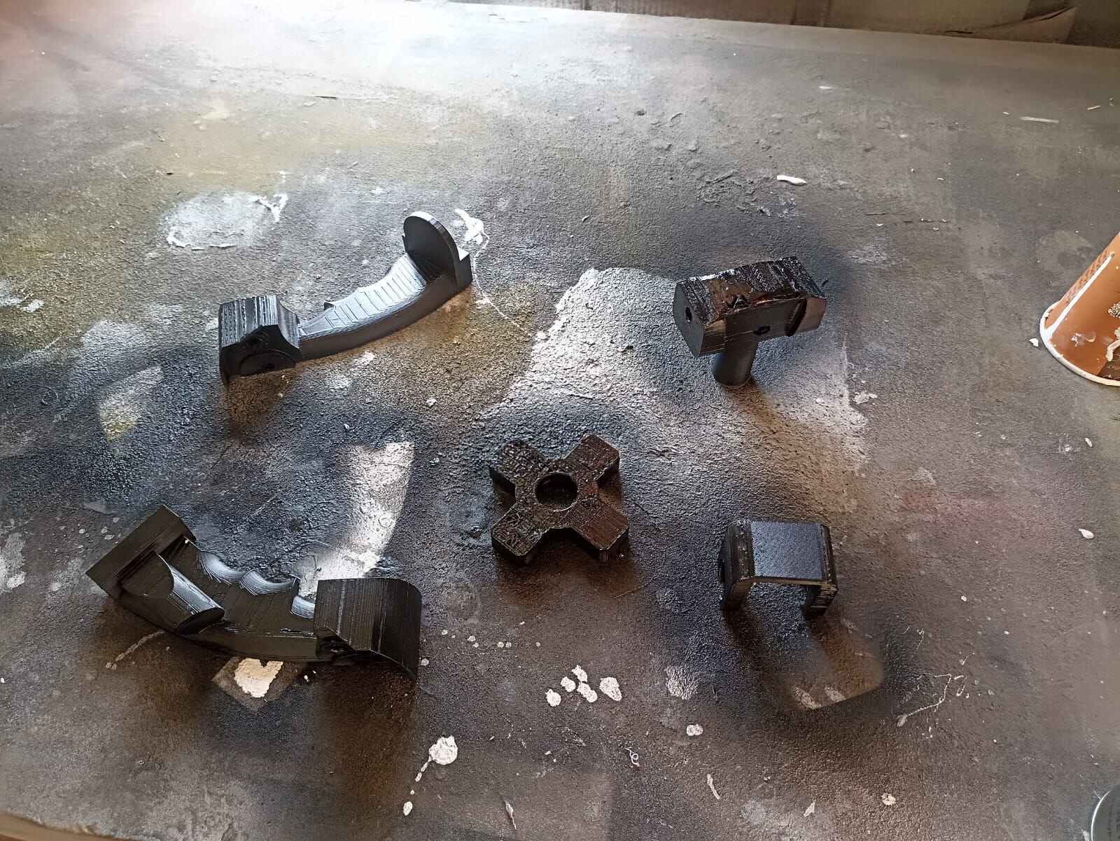
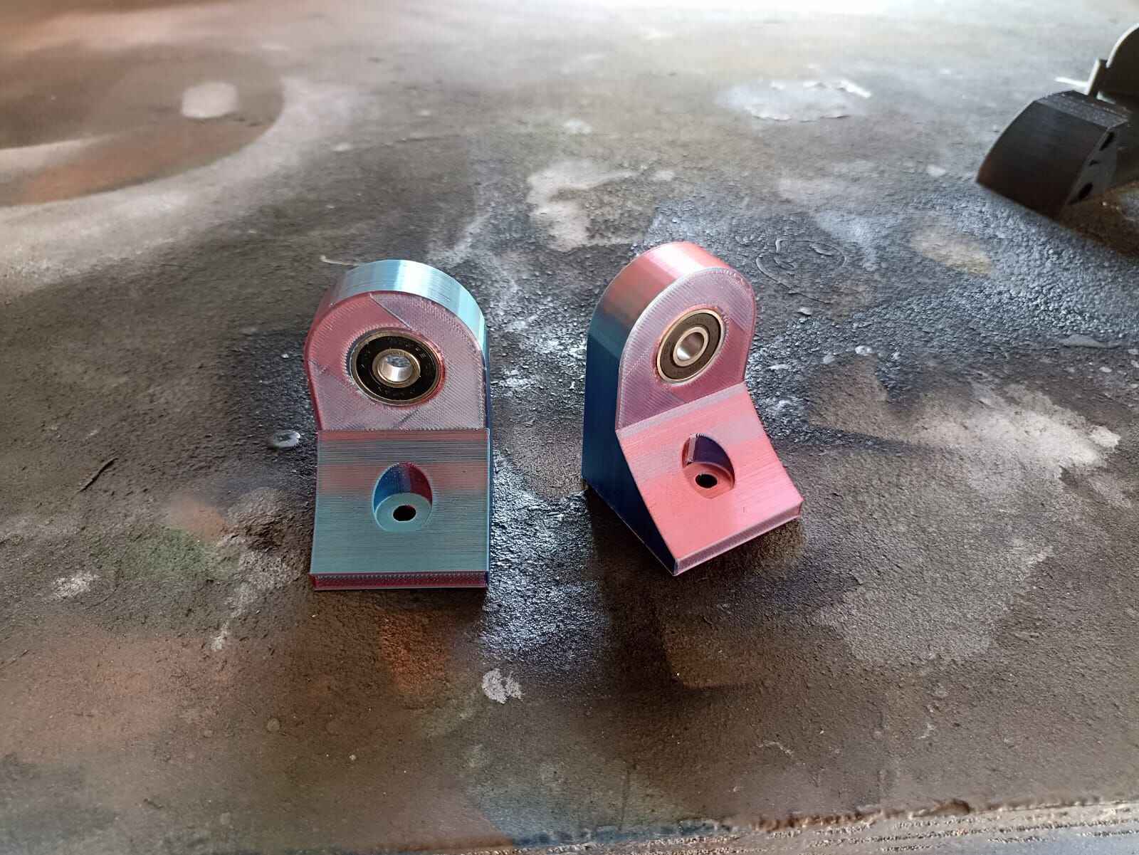
As you can see, I printed the joystick in 2 halfs, since printing it in one single piece would take a lot of time with a high risk of failing during printing, also it is easier to run cables down the middle in the future as you will see.
And before printing, I made a quick assemble of how the parts should fit to see if they did what I intended to do, and it did pretty well:
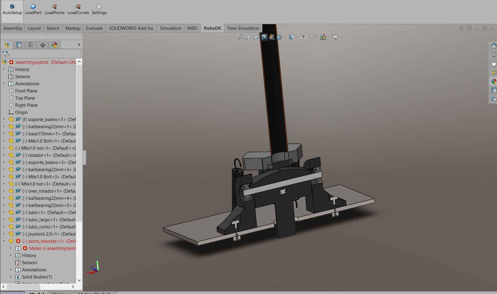
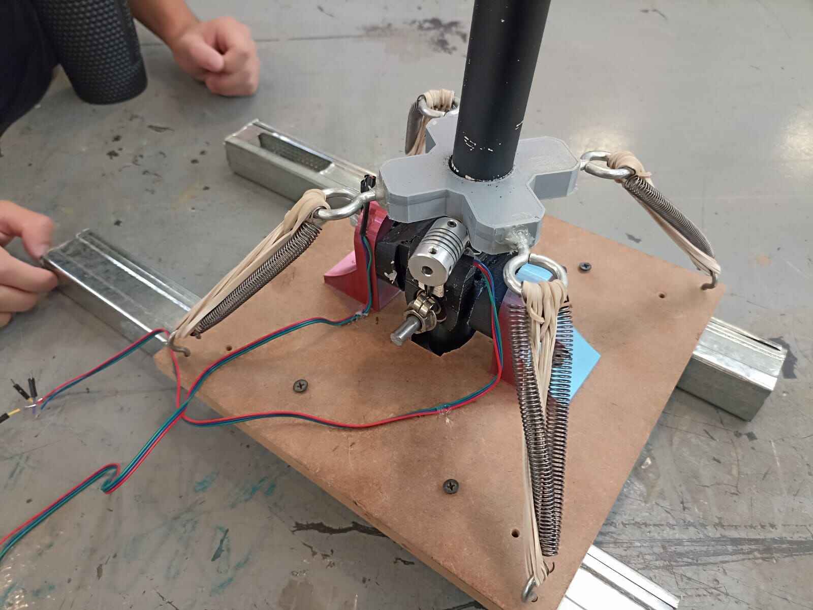
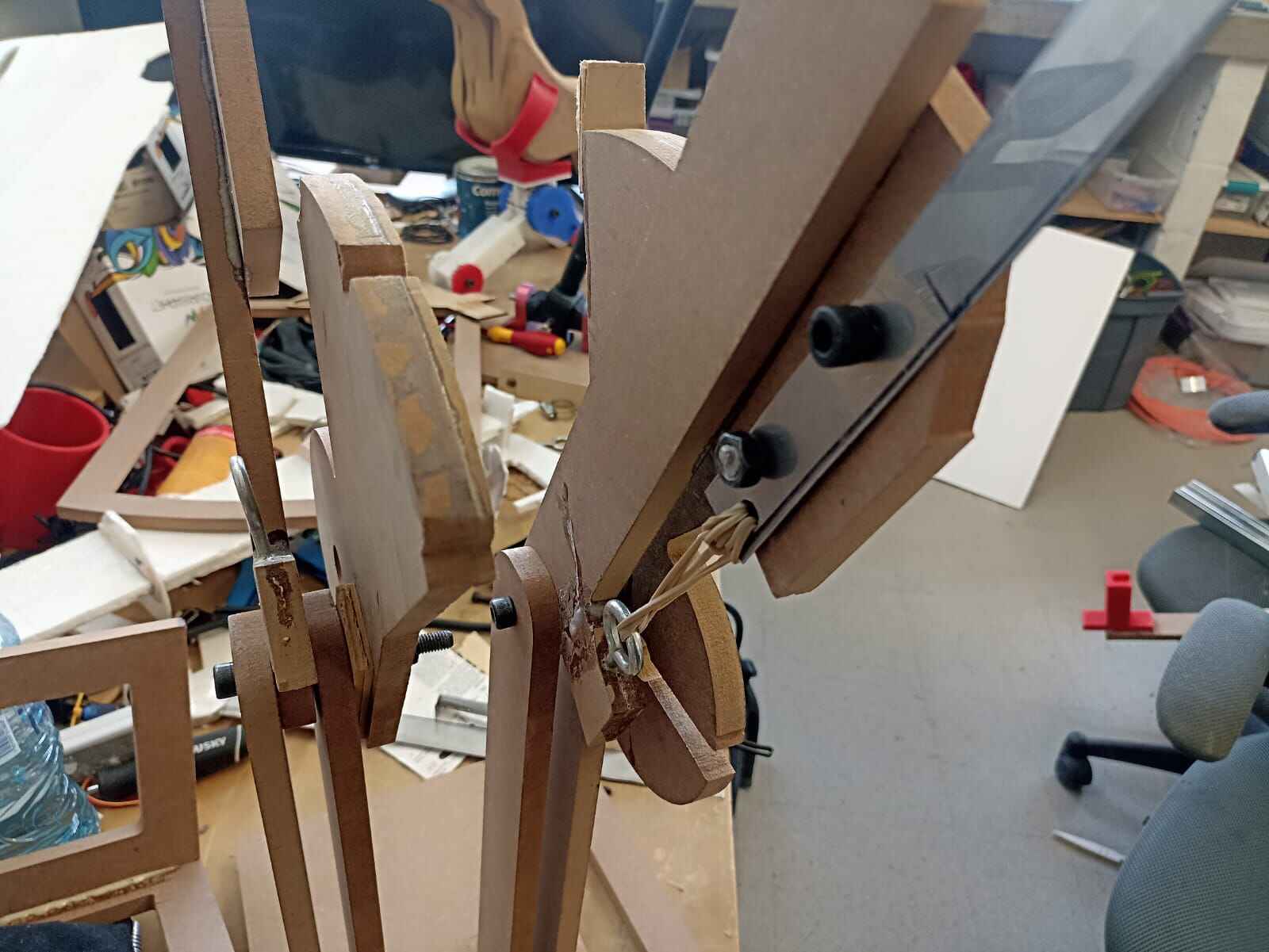
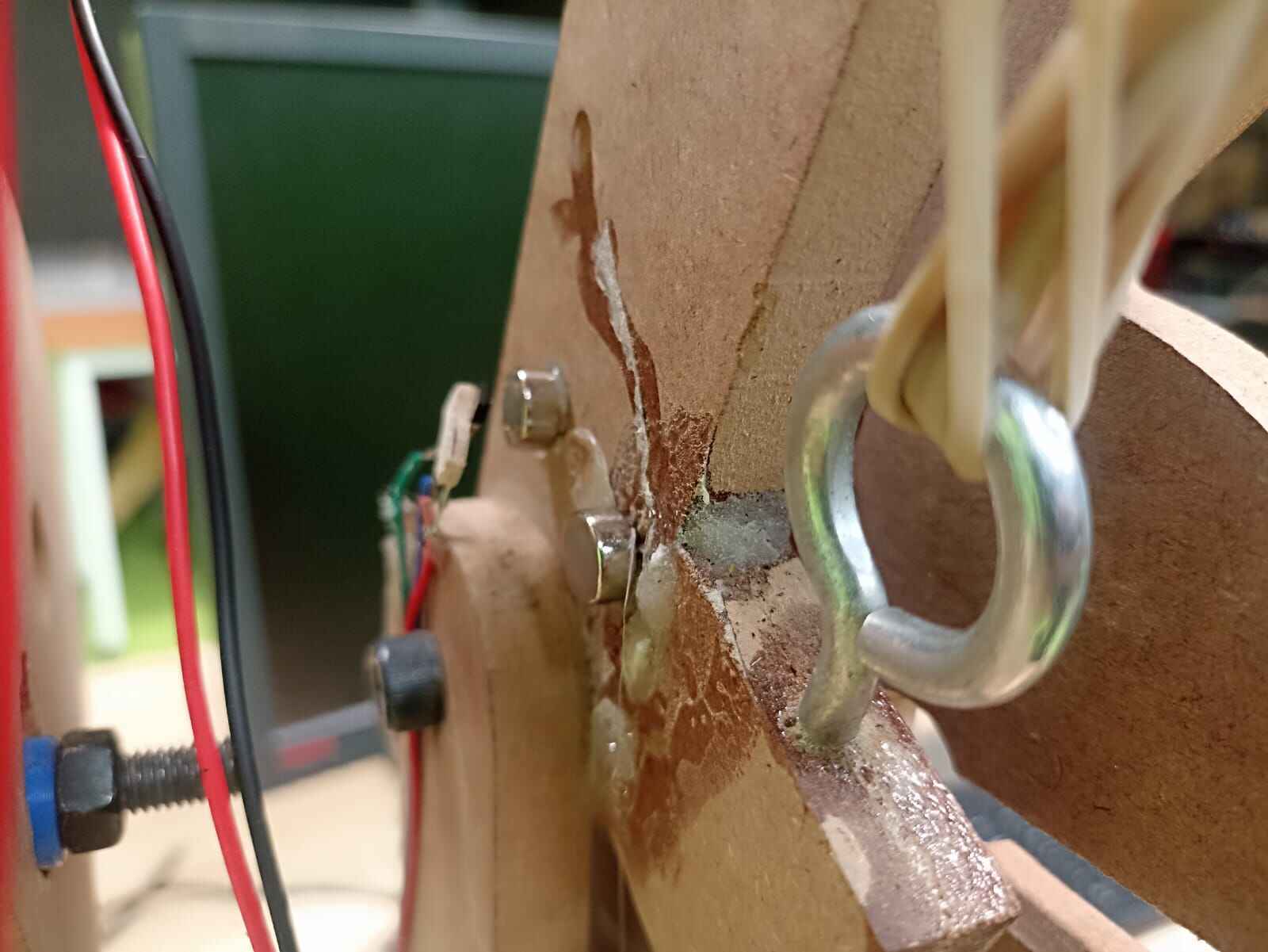
To add the resistive feel, I made holes in rubber band holder to attack eye bolts, along with adding eye bolts to the baseplate to attach the rubber bands
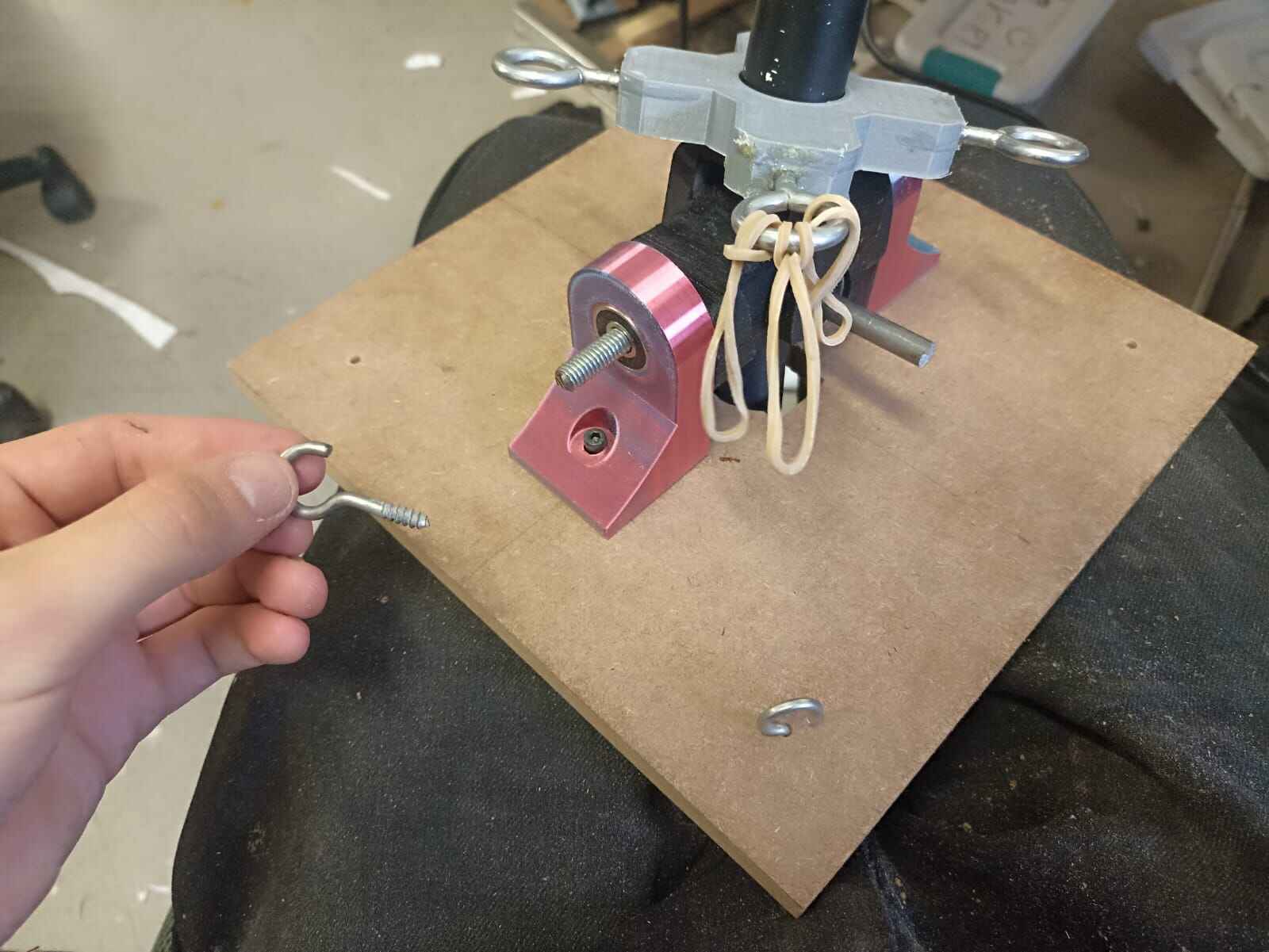
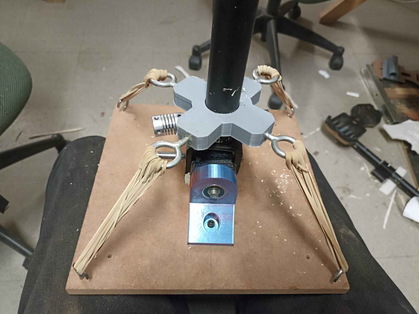
This is how much rubber bands I had to attach to give it the sort of resisistive feel (I added a couple springs later on for more firmness)
Again, don´t mind the mess in the background, but this is how the control stick bounces back to the center
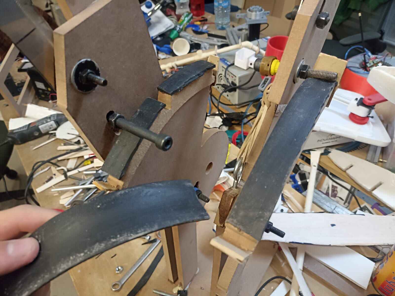
Let´s attach sensors to it. In the Input Devices Week, I explained the use of hall effect sensors, which is what I will be using to measure the change in posiiton in both axis of the stick. I took 2 of them and soldered wire to their 3 pins
The idea is to have either the sensors or the magents stationary, and having the other one move alongside the stick. For the magnets, I used 2 small circular neodymium magnets back to back, this was to amplify the magnetic field and give a better resolution to the sensor. So I hot glued the sensors to the rotor, and the magnets got glued to the rods.
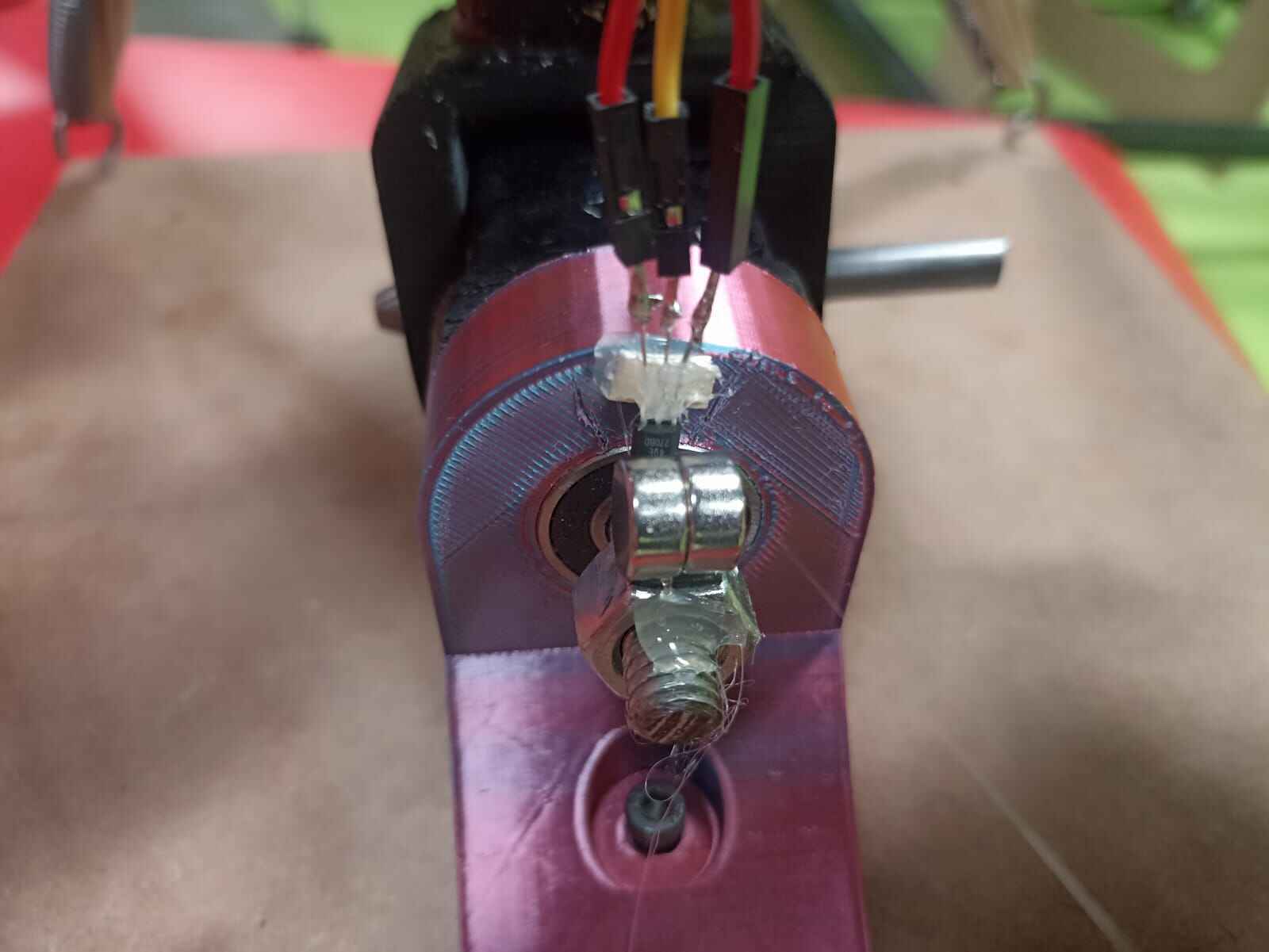
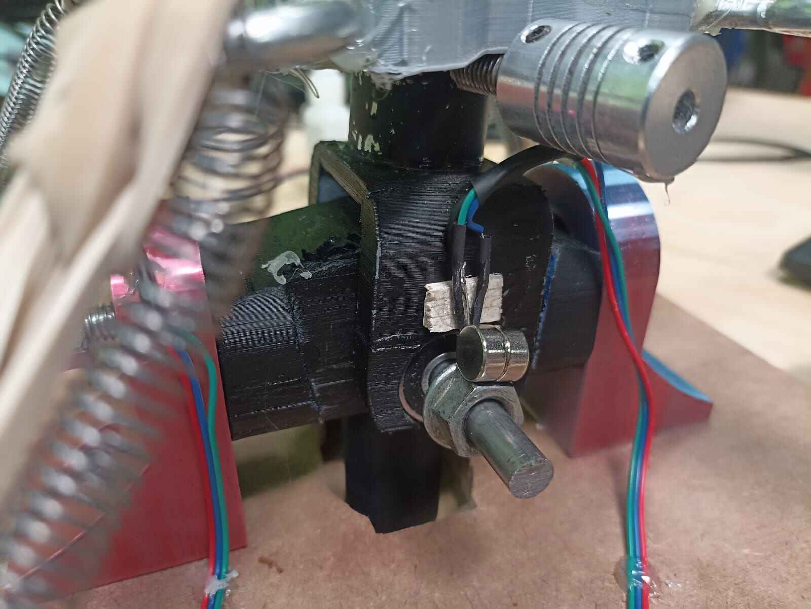
Note: when moving the center stick, the rod on the pink ball bearing holder was the rotating item, meanwhile, on the black rotor itself, the magnet was stationary and the sensors where hooked to the rotor and being moved. This doesn´t really matter as I previously mentionted, one element has to be moving and the other one stationary, doesn´t matter which is which.
To test how the sensors responded to the movmement, I connected the output to an Arduino and used the serial plotter to graph the input signal being recieved, it did with great success:
The signal would go up and down since the sensor was receiving both north and south pole of the magnet, giving it more resolution than being exposed to just one pole
Now, to hold the joystick still and attach it to the chair like I did on the 3D model, I bought metal profile to later cut and join together so I could screw everything together, it looked something like this:
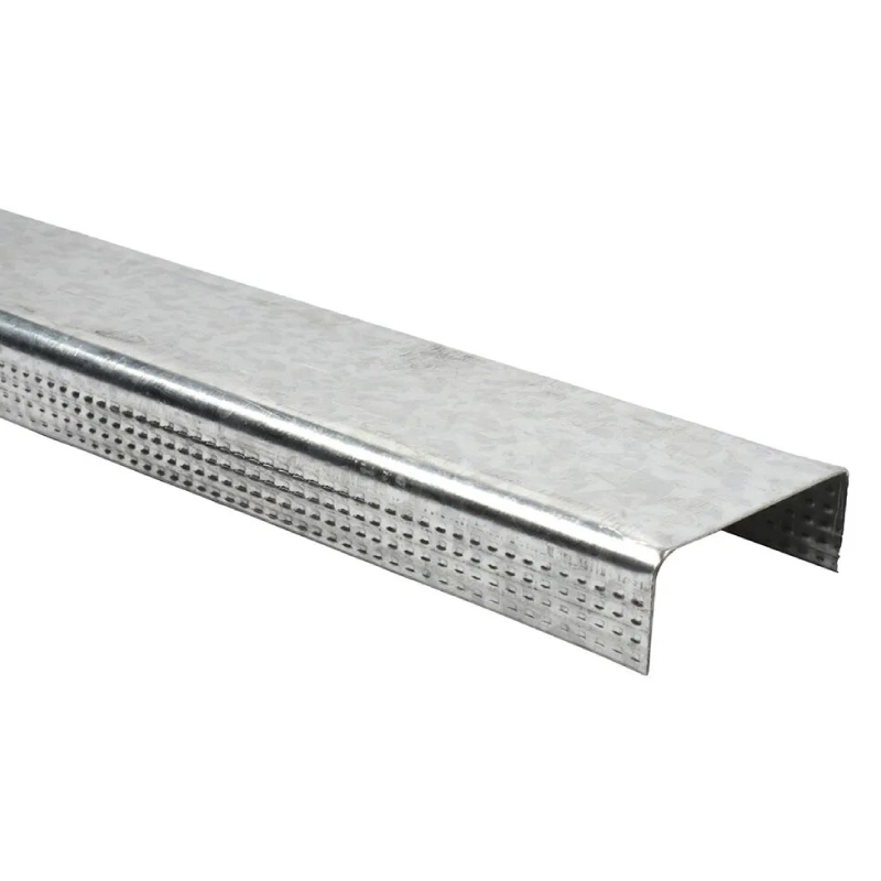
(Actually the one I picked came with 2 pieces overlapping themselves but I didn´t notice, but I thought that´s just how it was sold, so I technically stole one on accident... Home Depot please forgive me)
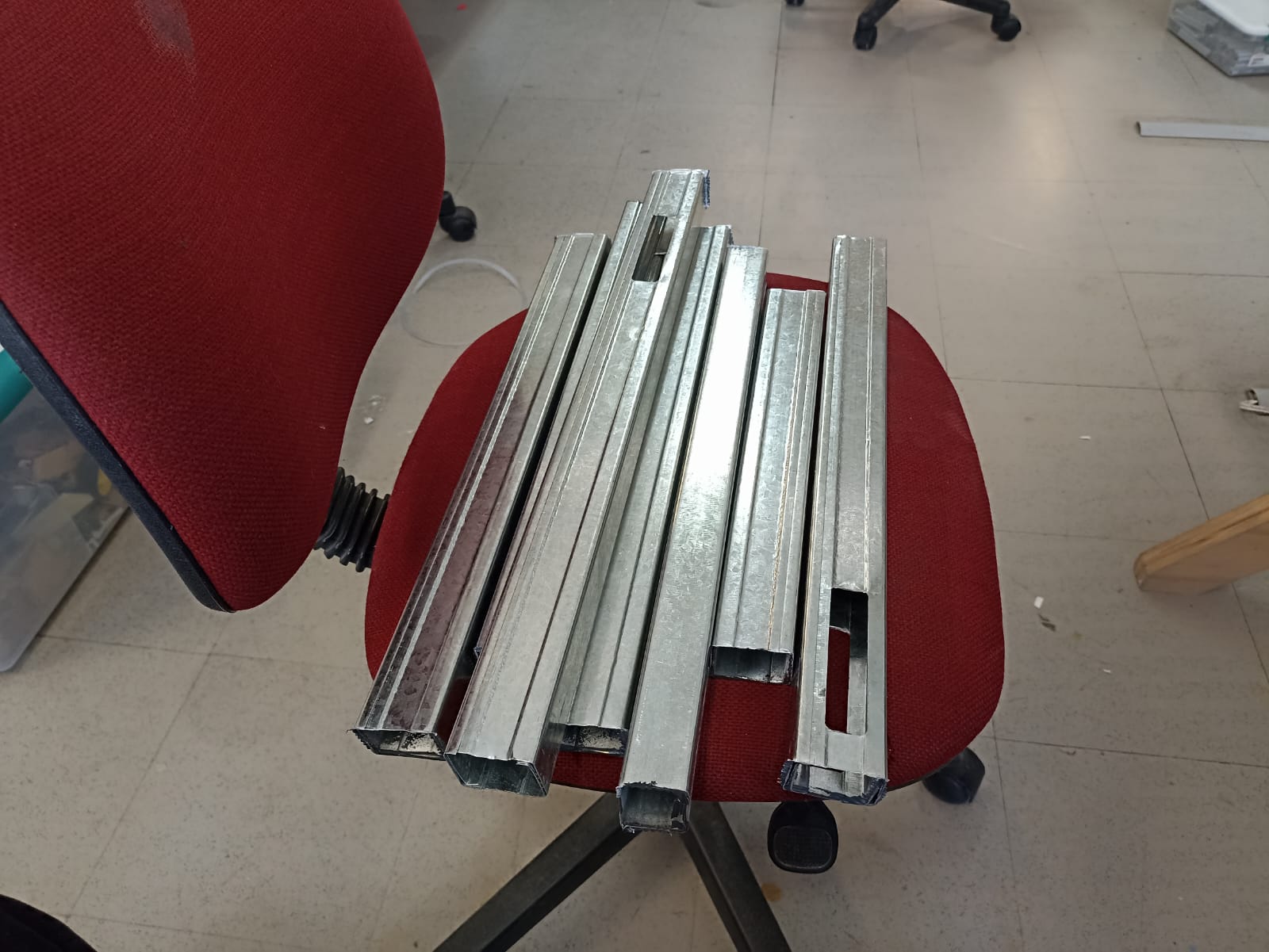
So I marked the distance I wanted the pieces cut and did so with a circular saw we have at Ibero
These are the outcomes pieces:
Here you can see the pieces being screwed to the baseplate of the center stick
Rudder Pedals
As the third piece of the controls, I´m also doing rotating pedals to control the rudder of the airplane
We firstly have the pedals themselves, they are cut in 12mm MDF on the CNC router (explained later). I measured them so they would fit my boots, which is about 30 cm. Also they have a little holder on the bottom to rest your foot.
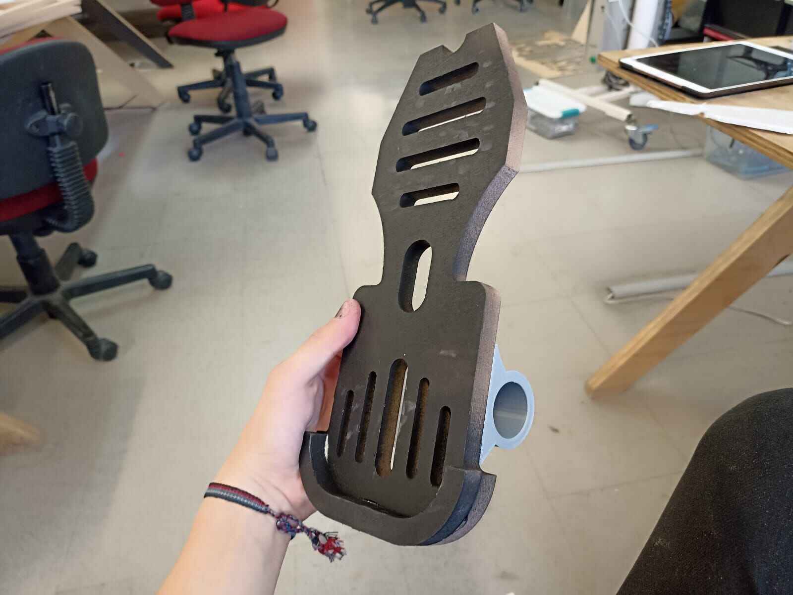
You can also notice a 3D printed piece on the back, this is to fit a 1" PVC pipe to make it rotate through an axis.
The center of the axis of this rotation is in this other 3D printed piece that will be fixed to the assembly
 }
}
The pedals can rotate freely along the pvc pipe, but we also need to measure the movement somehow.
I thought of a way for the rotation of the pedals to move some MDF sticks so I could rotate them along a fixed axis and measure the change with a potentiometer, like so:
Turns out measuring the changes in the rudder is complicated for 2 reasons: Since we are moving the whole system with our feet, whatever material or assembly tends to break down due to the force and weight applied to it. Also, even with the system I invisoned, the is very little resolution for a potentiometer to pick up and be remotely accurate at the moment of flight.
Alright, moving to throttle.
The idea behind this is 2 rotating handles that control 2 things: on the left side we have the flap position, and on the right we have the throttle, or the ammount of power in the motor.
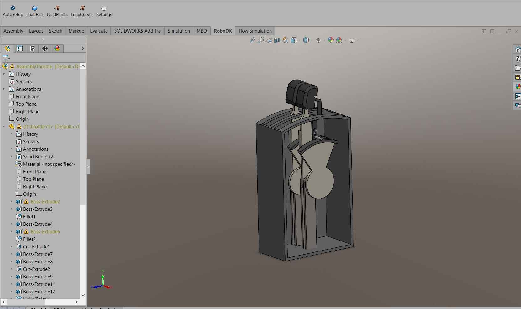
I also wanted to give this some sort of resisitve feel, so it would be more realistic. Let´s look at the section view from behind.
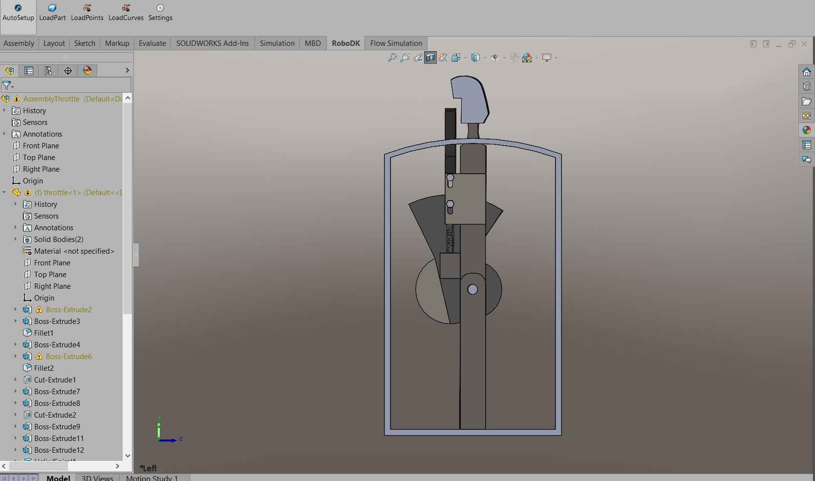
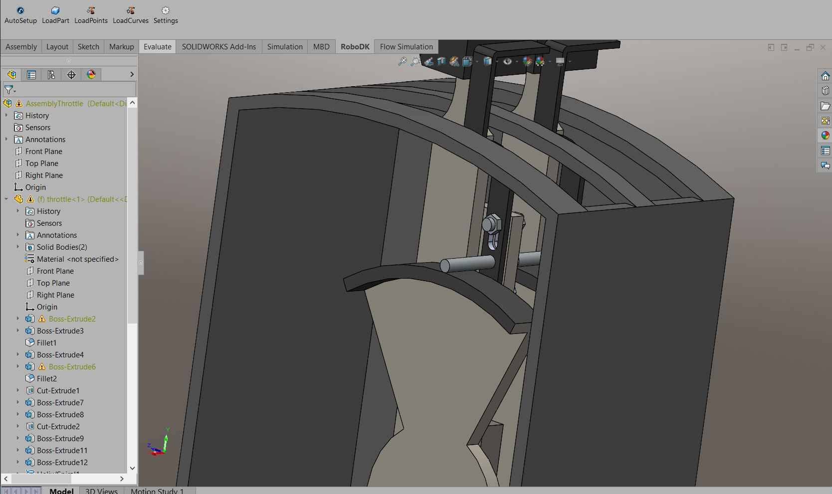
It may look a little confusing but it´s a very simple mechanism. The main shaft with the grip rotates from left to right, but it´s being pulled down by a spring (or yet again, a rubber band). When being pulled down, the rod seen on the second picture pushes against the semicircle piece, creating fricition, giving it the resisitive feel. This rubber band can be pulled up by a handle in front of the grip, lifitng the rod and eliminating the resisitve feel.
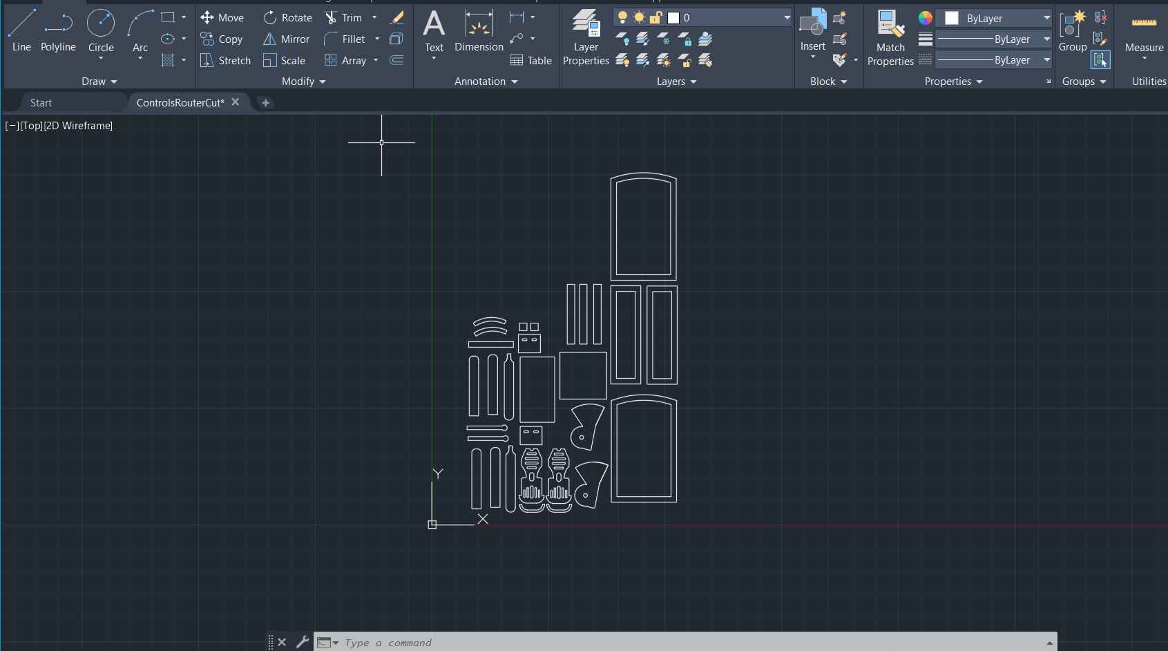
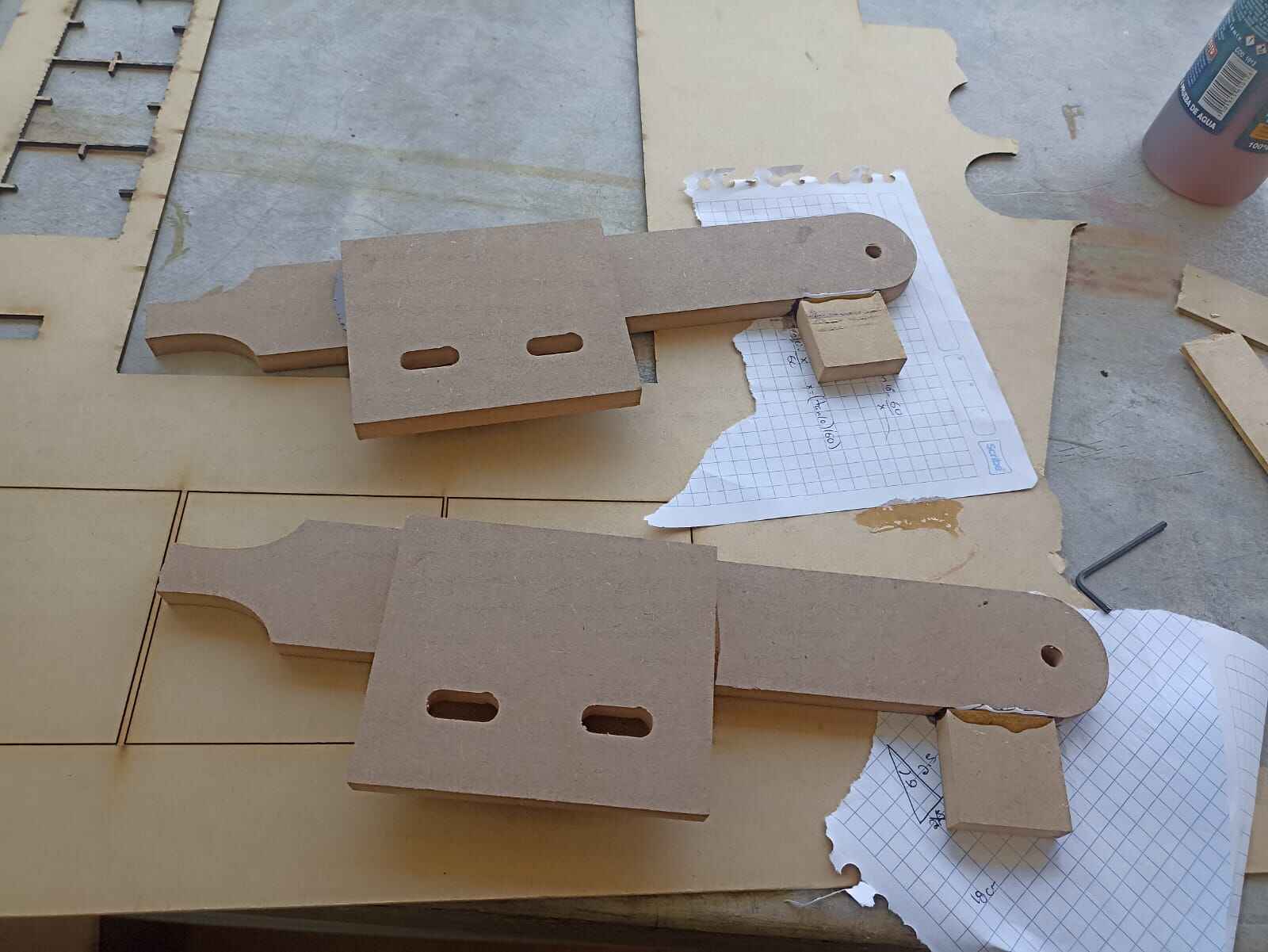
With that being said, almost all of this assembly was cut in the CNC router. I exported each piece as a DXF. We do this by facing the piece we want to trace, File -> Save as -> DXF. This should pop a menu that gives you a preview of the DXF being exported, so I did that with all the pieces.
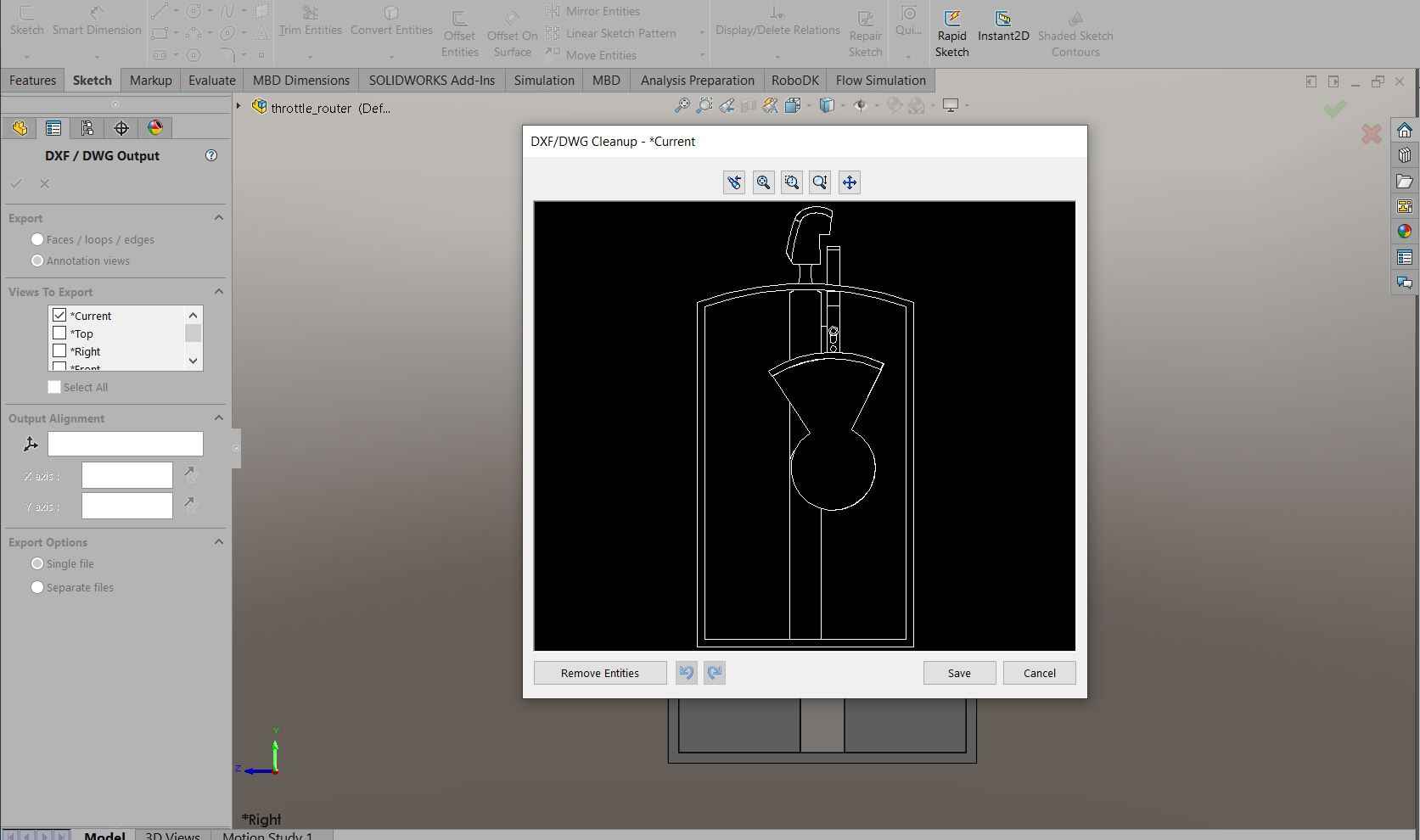
Once I did all the individual pieces, I joined all of then into a single DXF file to cut
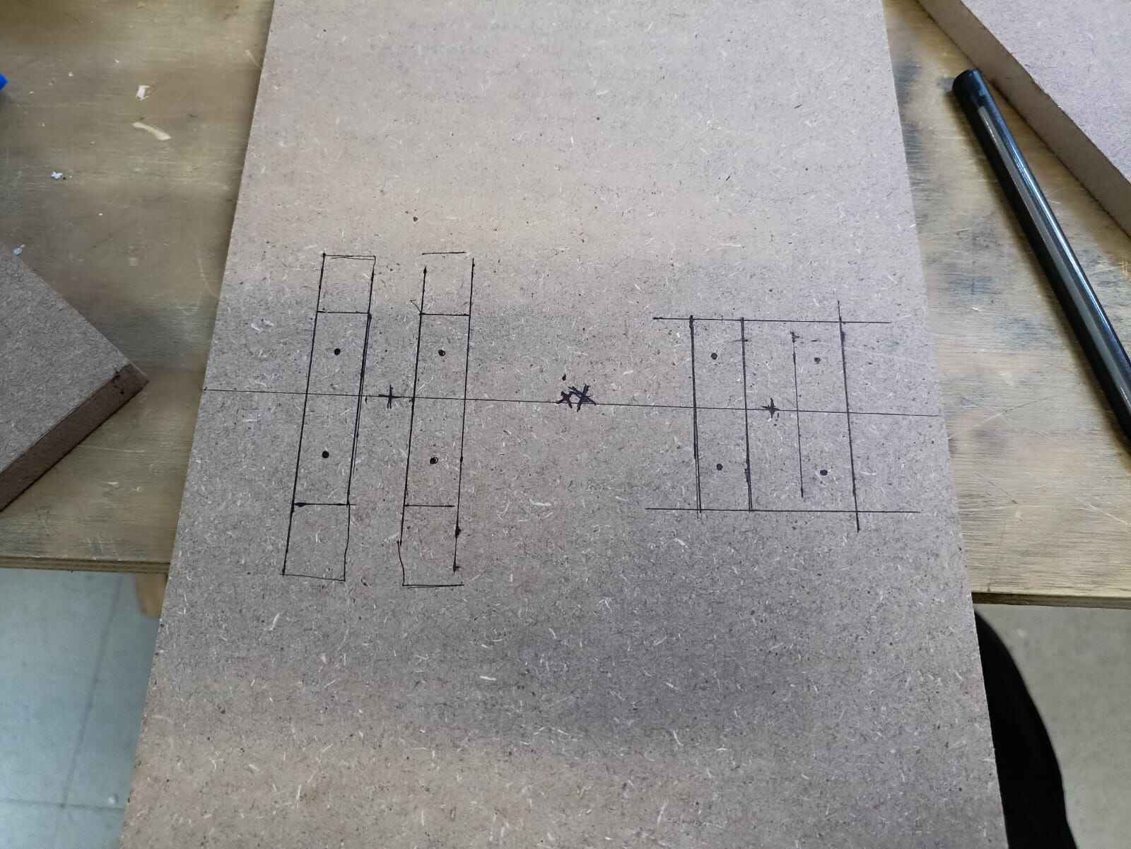
With all the pieces, began by tracing where the rods should go, and driling to add wood screws
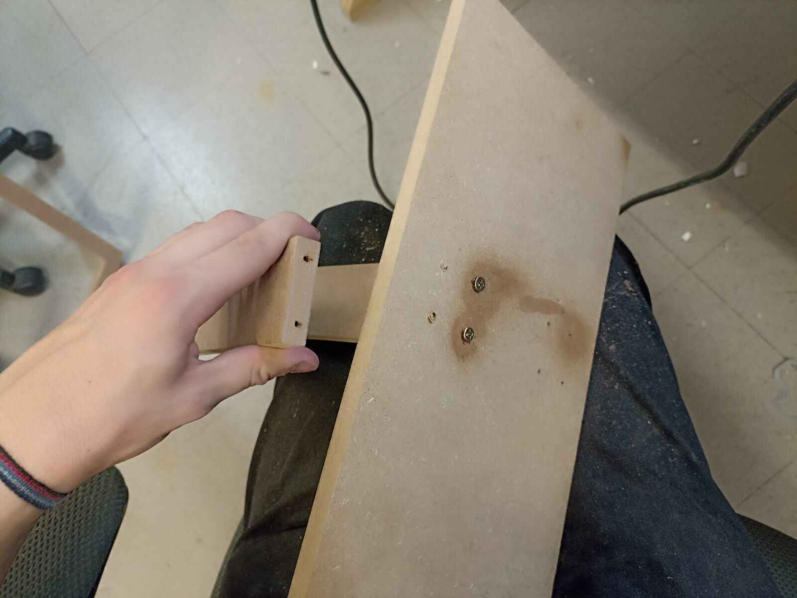
I glued some of the pieces togehter with wood glue
And later added the eyebolt to hold the rubber bands
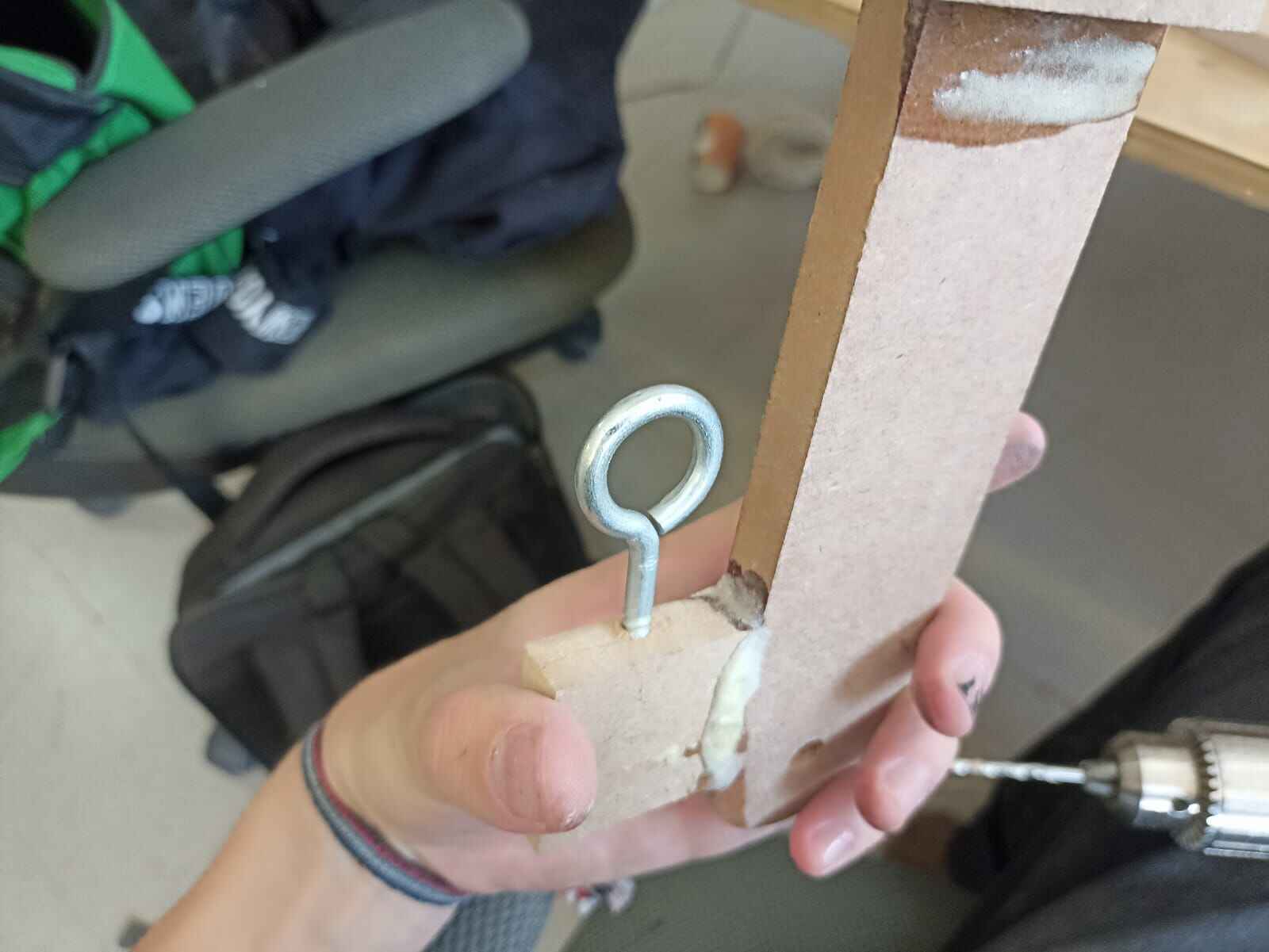
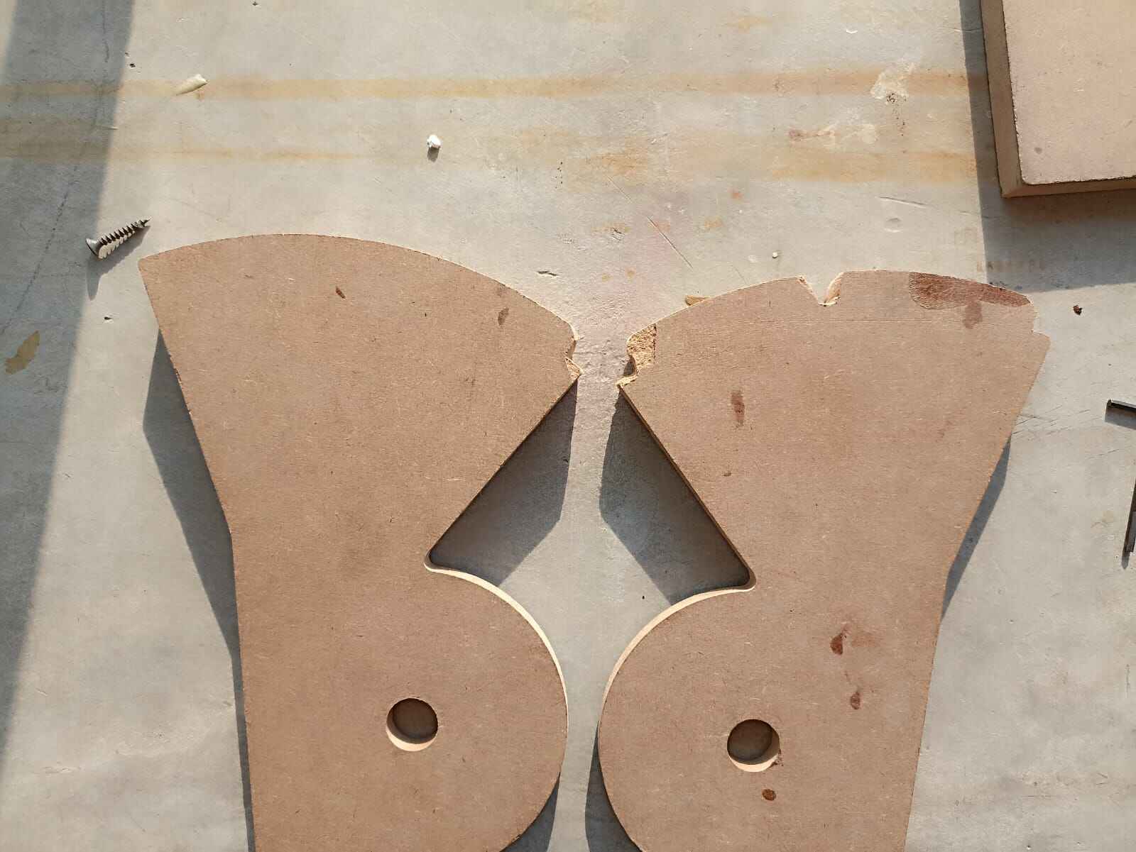
Now, for the semi circular pieces that followed the trayector of the shafts, I wanted to add a couple of dents on certain places. I did this with the intention of getting the rod stuck on certain parts and stopping the movement of the shafts unless the rubber band was lifted. This is again in the search of realism, as in airplane flaps selection, the pilot has to lift the lever to move and select a different flap selection. I also did so on the throttle so it would get stuck on the zero position and prevent it from accidentally moving and accelerating the aircraft by accident.
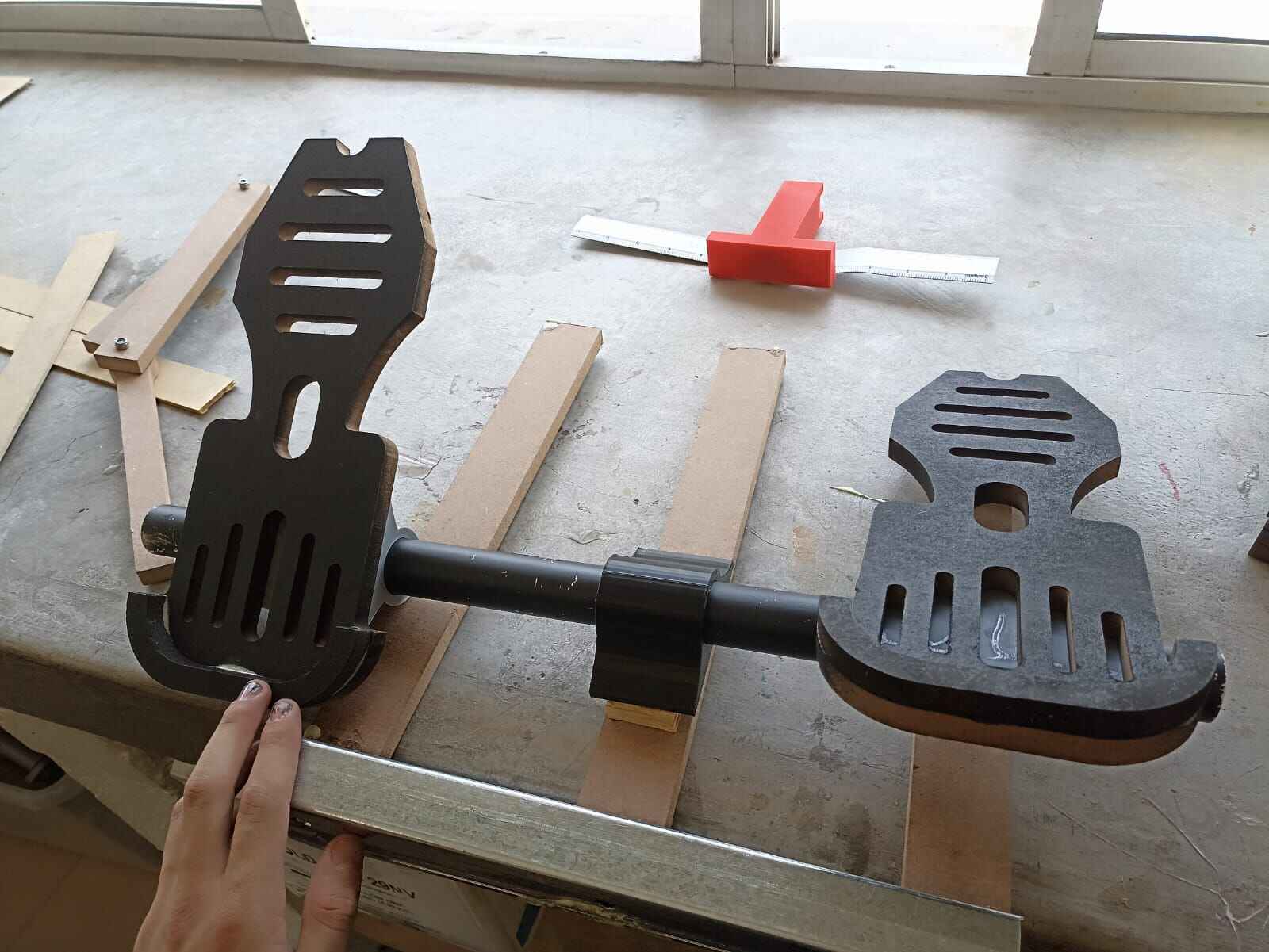
On the meanwhile, this is the first assembly of the shafts alongside the semicircular pieces
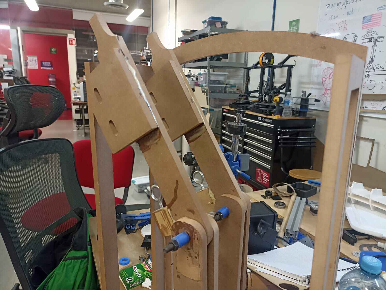
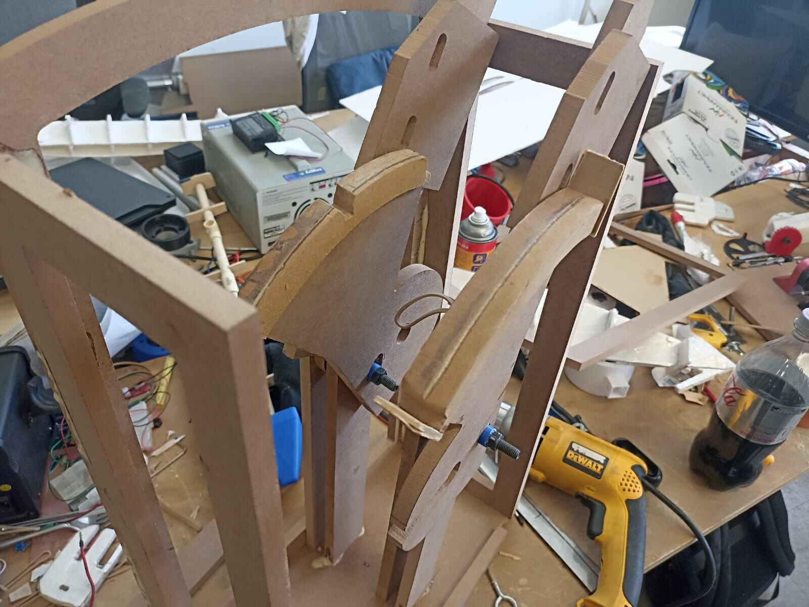
This is how the movement should look like:
For the rubber band, I took a scrap piece of metal, drilled a hole on one end for the rubber bands, and other for the screws that held it to the shafts
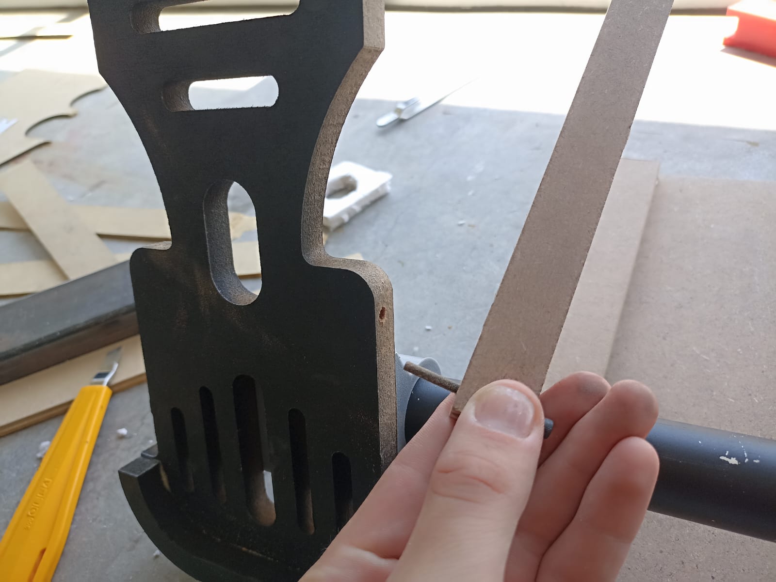
I added screws as the resisitive feel rod, and simulated the movement.
As you can see, the throttle gets stuck on the beginnig and can´t be moved unless the rubber band is pulled, and the flaps have 3 different positions where to be.
To get even more resistance, I glued a rubber strip onto the semicircle to increase the friction
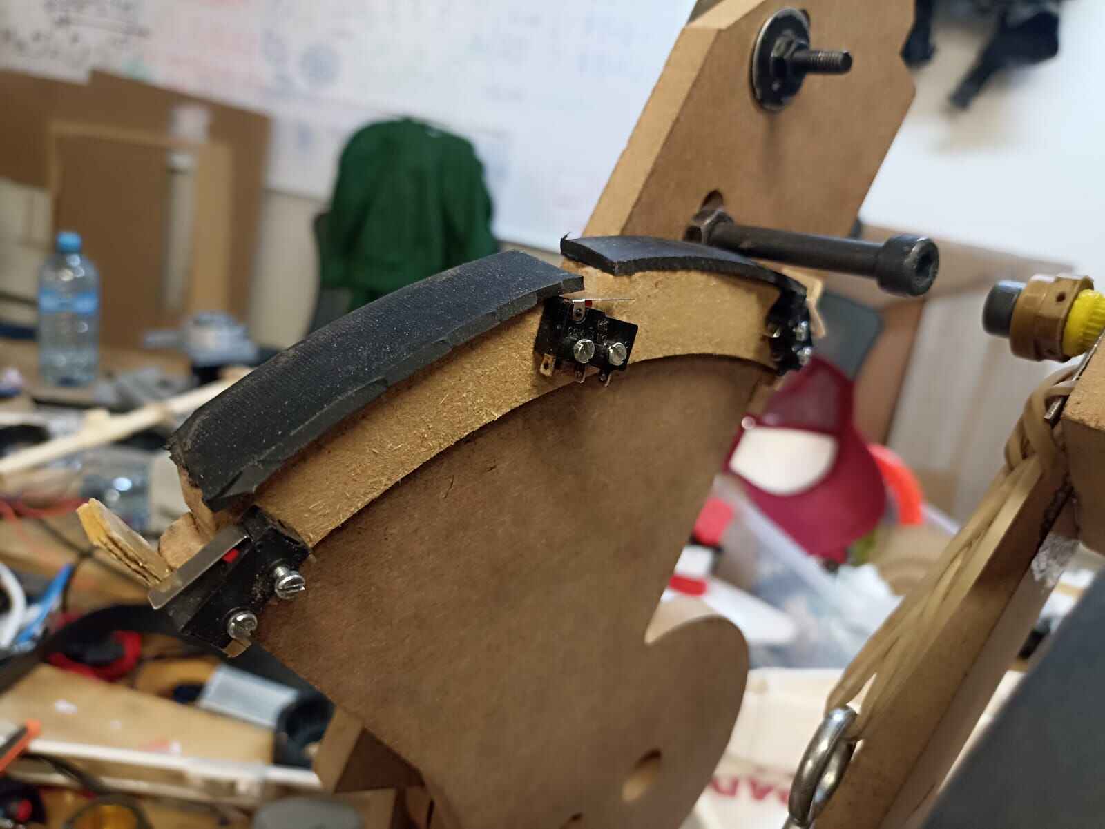
To detect the position of the flaps, I added limit switches in each dent so the rod would push it down and be detected
Now, to sense the position of the throttle I will be using hall effect sensors again, just in this case, I will be using 2 separate magnets. Since the distance the shaft moves is more than what the sensor can read from a single magnet, I will put 2 magnets; one south side up and the other north side up. This way, we can extend the resolution of the sensor into something we can read
Assembly
Now that we have all the individual components working, we can begin to join what we created to make the prototype.
Important Note: The scope of this project was to move the surface controls of an airplane with the semi-realistic controls. Doing a wireless version that can be flight tested requires more complex electronics that I attempted to make. Mainly using XIAO ESP32, which have a wireless communication protocol called ESP-NOW. I came around to try using those instead of the RP2040 version to see if I could actually try to fly this thing. But I ran into 2 issues; the first being that using servomotors in XIAO ESP32 is close to impossible, as adviced by classmates and professors. I even attempted to use one to no success. And reason number 2 is apparently bad luck on my part, since the 3 XIAO ESP32 that I had stopped working without apparent reason. In the spirit of not giving up, I will later try and use ESP32 WROOM modules in an attempt of having a wireless version of the whole project, since using comercial microcontroller modules is not in the Fab Academy spirit.
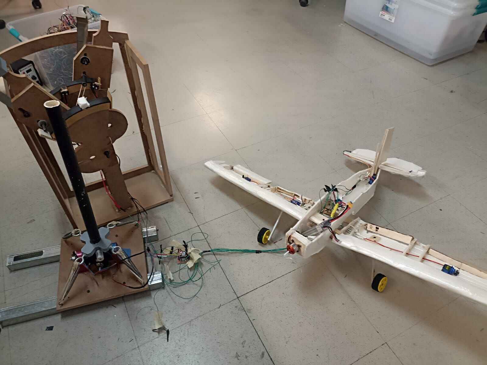
With that being said, the assembly will consist of a wired test, to prove the concept even works at all.
To start, I added extra long wires to the connections I had on the plane. If you remember, the wiring on the plane consisted of joining all the 5 servo´s voltage wires together, and did the same with the ground ones. I only left the signal ones by themselves to be connected to the PCB individually. This way I had 8 wires in total sticking out of the airplane
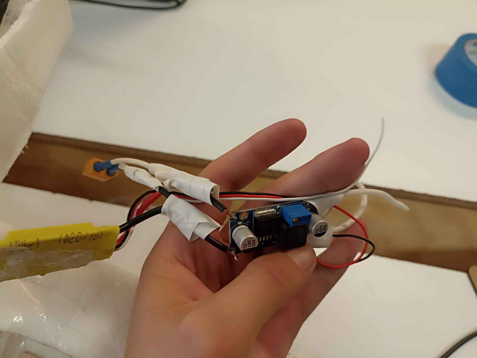
Also, since running the 5 servomotors from the computer could be dangerous as I could potentially draw too much current and destroy my computer, I decided to feed the entire system from the LiPo battery. The way I did this is I connected a LM2596 voltage regulator in parallel to the ESC. This regulator drops the voltage by a specific ammount that can be selected by a potentiometer inside the module. So I set the output to deliver 5 volts. This way, all the system, including the XIAO RP2040 could be powered without the need for it to be plugged into a computer.
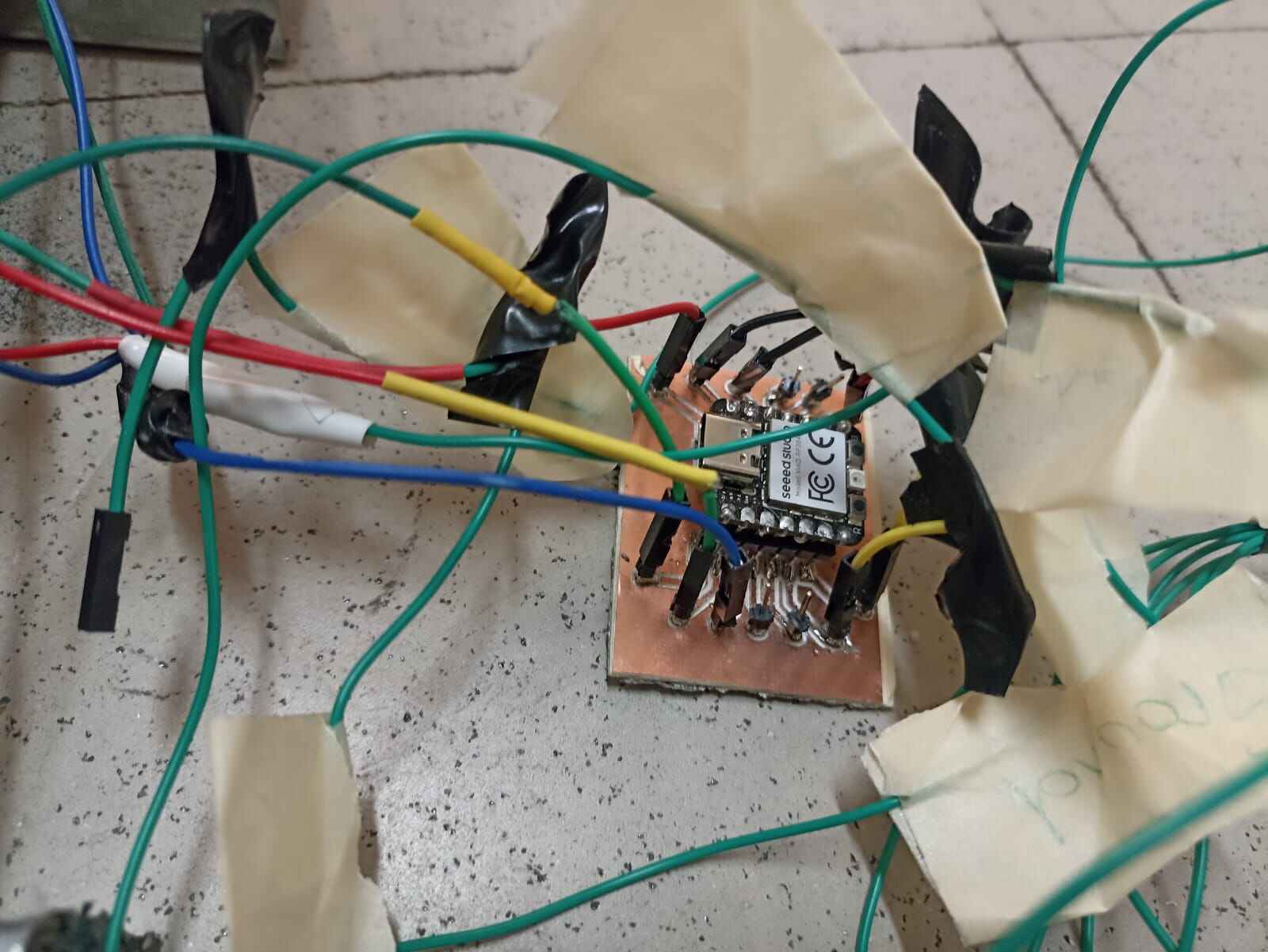
The assembly would be controlled by the XIAO RP2040 I did on the Electronics Design Week.. It has male pinheads that connect to 5 volts, ground, and 11 other GPIO´s,
So the way that I joined the electronics was to connect all the voltage wires from the controls (Hall effect sensors, and limit switches) together with the voltage wire from the plane, and it would also connect to the 5 volt pin in the XIAO to give it power. I did the same with the ground wires, and for the individual wires; Hall effect analog inputs, limit switches and signal wires from the servos went to a different pin each to be programmed individually.
Once we have the connections, let´s take a look at the code:
- Define pin numbers: assign the name of the variables to specific pins on the XIAO
- Create/Attach servos: Servos are declared and attached to their pin number
- Initialize brusheless motor: Since brushless motors works very similarly to how a servo does, we attach the motor to the it´s respective pin, and delimit it´s power values from 1000 to 2000. writeMicroseconds is just a quick protocol signal that gets the motor to a ready position.
- Read analog inputs: We assign a variable to the analog values of the 3 Hall effect sensors.
- Mapping: This function creates another variable which value depends on 5 parameters; a changing value (in this case, the analog values from the sensors), we declare the lowest and higher value we expect from the changing value (in my case, the lowest value the hall effect sensor did on full left position was around 630), and the range we want the new variable to have, meaning the value of the angle of the servo. It basically translates a certain value in a parameter to a range in another parameter.
- Servo Positions: This writes the positions previously calculated into the servos
- Print information: This displays the data from the analog values emitted by the sensors, and the value position of the servos and the motor.
Now, you may notice that the limit switches for the flaps were not included in the code. This is because whenever the switches were declared, for some reason it interfiered with the analog values, adding tremendous ammounts of noise to the values, and creating erratic moves on my servos without me interacting with them:
So for the sake of having stable and predictable controls in my prototype, I decided to temporarly leave out the switches in the equation.
And after so much trial and error with the code and the wiring, the proof of concept worked: