4. Electronics Production
PCBuilding
This week, we will build our own printed circuit board from (almost) scratch. With the intention of using the XIAOESP32C3 module to program other ESP32 modules for our future projects. In here, we will learn the basics of CNC´ing the board itself using a copper clad laminate, which is basically a glass fiber plate with a thin layer of copper that we can engrave traces on to solder our components into. Eliminating the need for wires and flimsy connections that can deteriorate or break with time or manipulation. Leaving us with a solid assembly of our circuit and it´s components.
For detailed extra information I will be leaving here the link of the group page describing some concepts and parameters for PCB building that I will use for this week: Electronics Production
Also, for further information about sending any PCB to a board manufacturer for a professional finish is found on the Electronics Design Fab Ibero Puebla´s Page in the Electronics Design Week
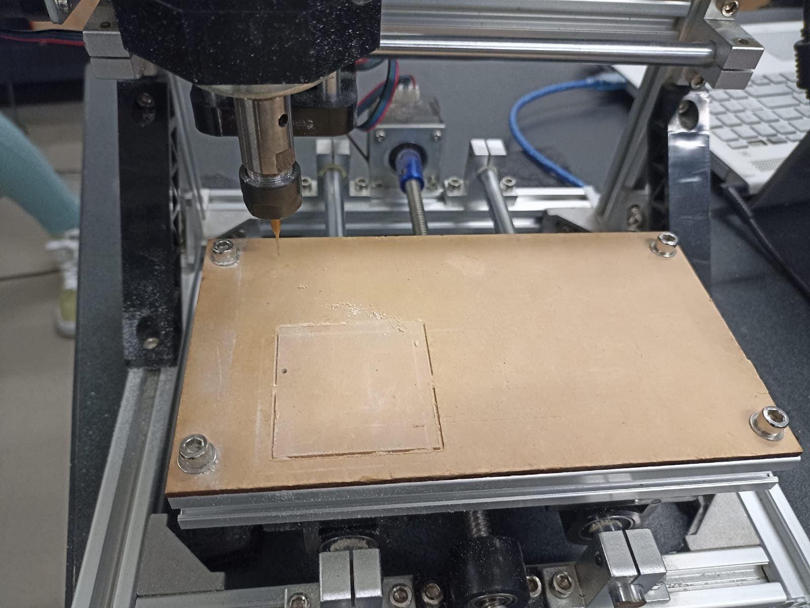
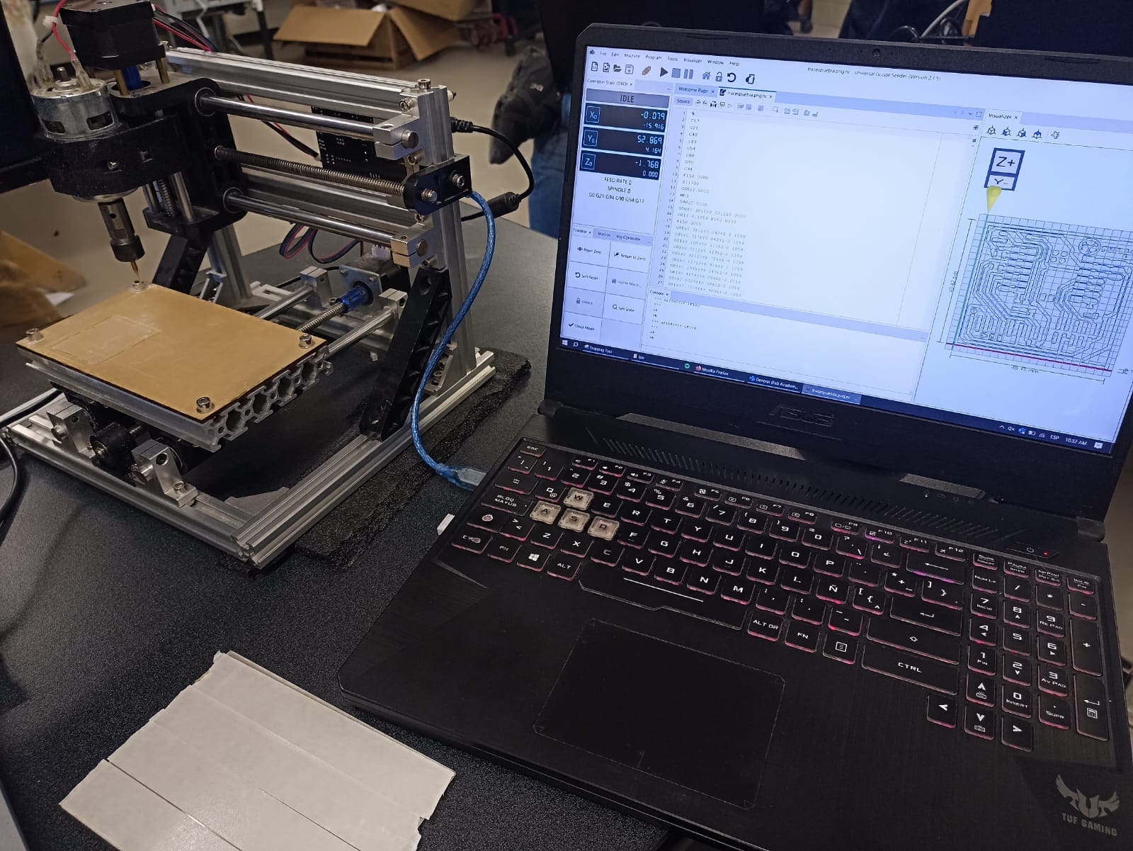
Firstly, the CNC machine I will be using is somewhat of a self made one. It doesn´t really have a brand so I can´t put the specifications of it, but it should work just like the rest of PCB engraving machines. The program to run the CNC in my case it´s UGS Platform
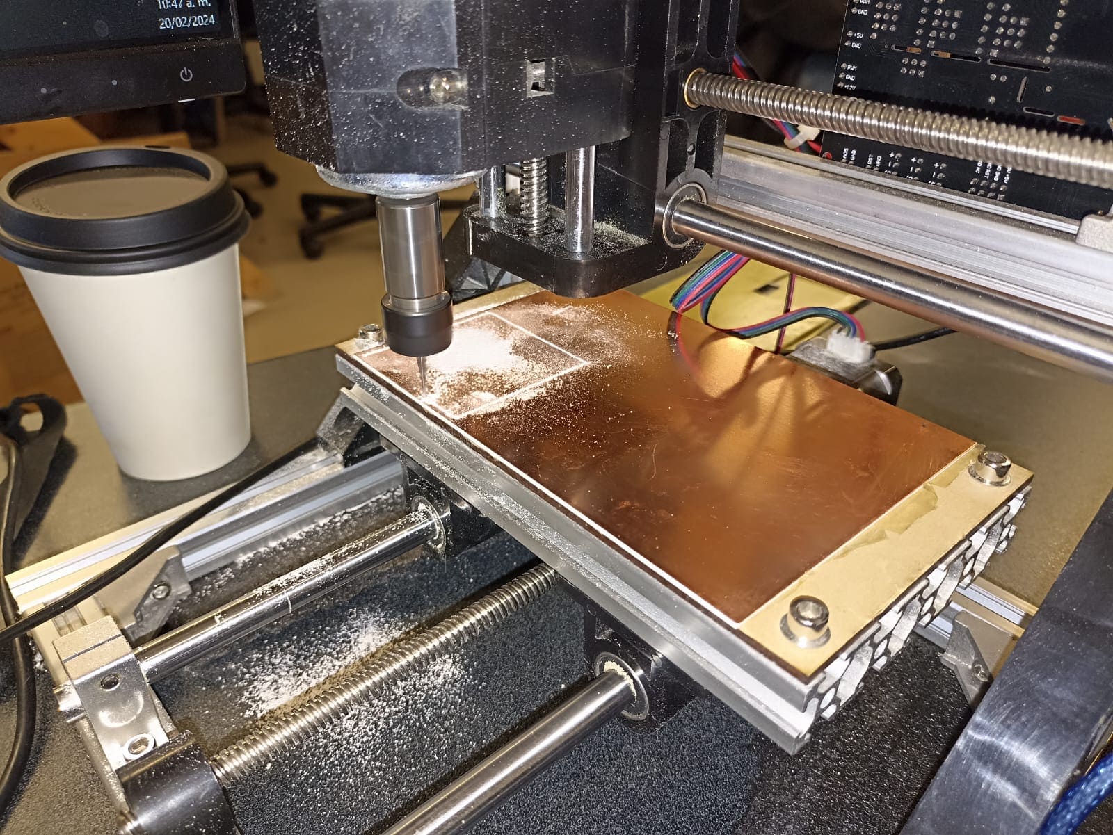
To start we have our "sacrificial plate"; an MDF sheet attached to the base of the machine that will protect it from the drillbit when it goes through the laminate, as you can see from the traces made by a previous cut
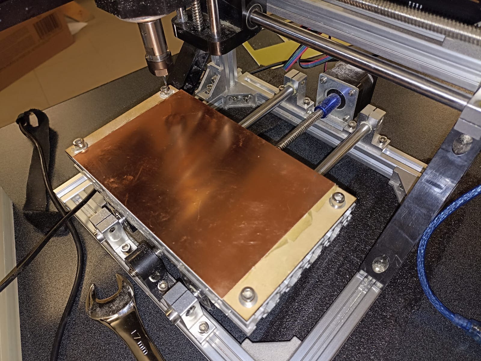
This is our copper laminate, it´s the same size as the bed of the cutter
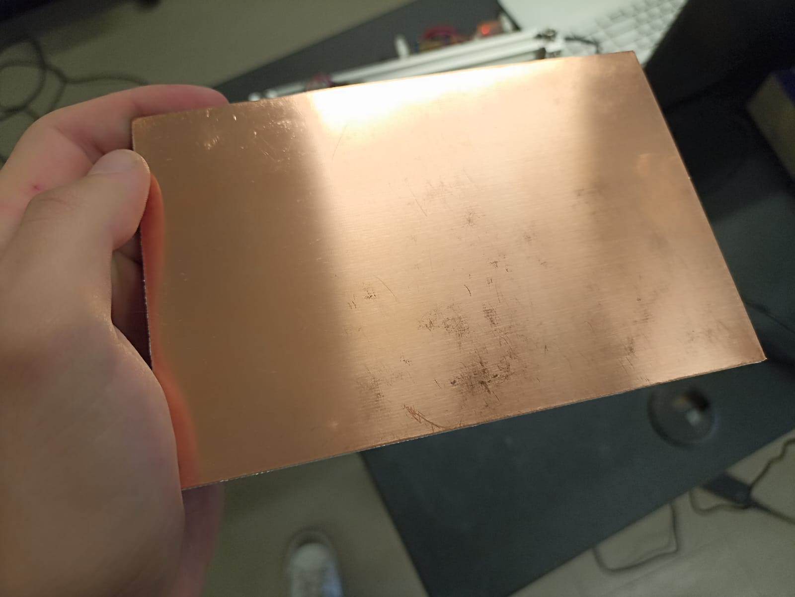
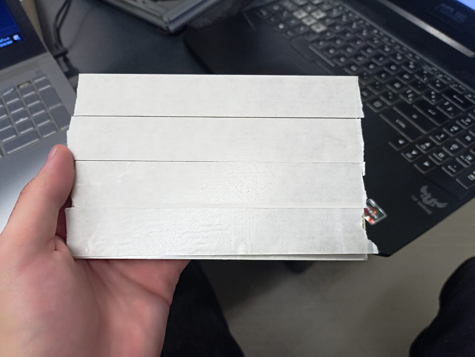
To attach the plate to the bed, we used double sided tape on the back of the laminate. Important that we use tape on most of the surface to prevent it from moving and ruining our PCB while it cuts.
Once it´s pasted, we can connect our PC to the CNC
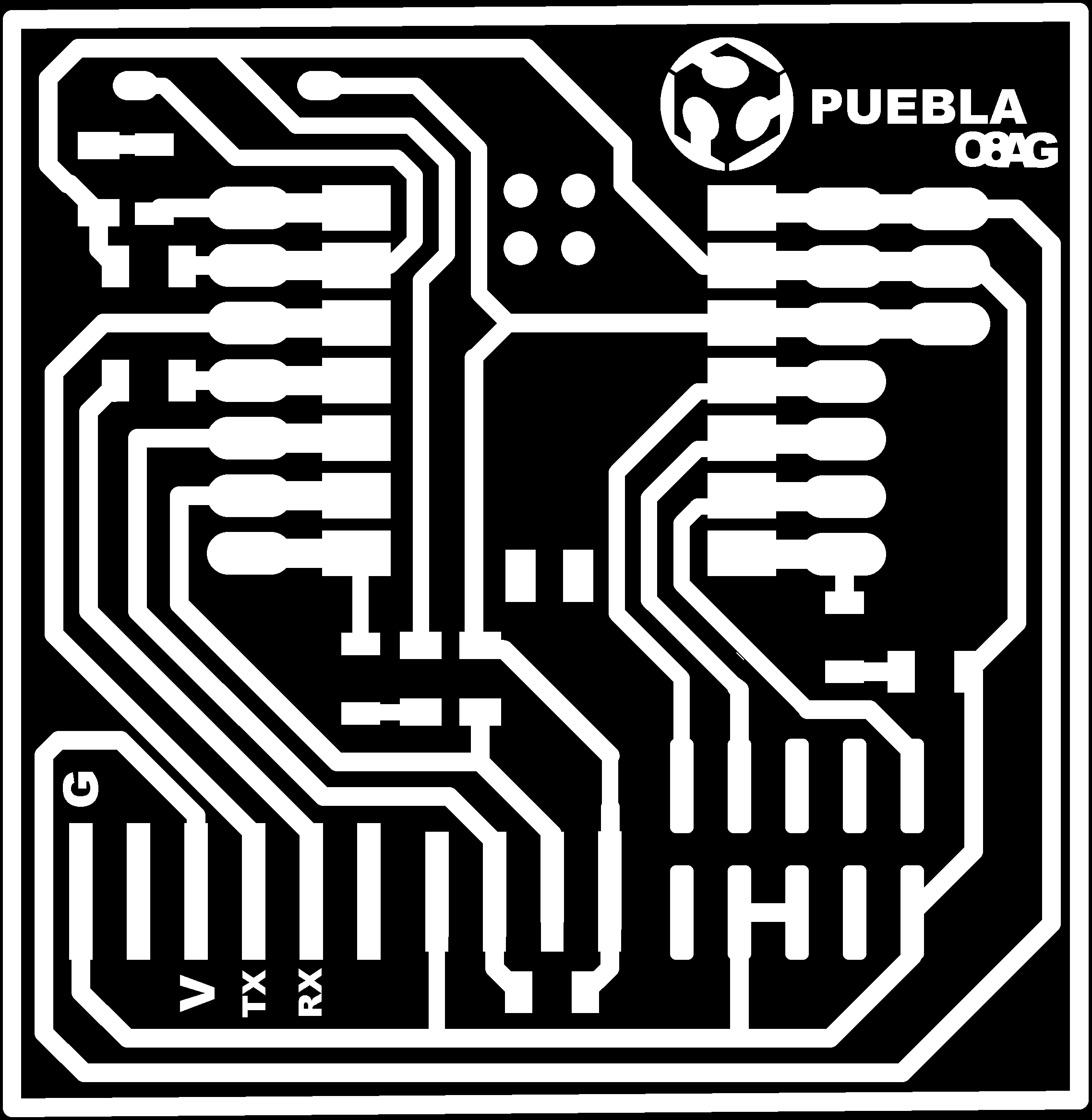
Now, for the actual design of the PCB, I will be using one provided by our professors here at Ibero. These are PNG´s that contain a black and white outline for where we want the drill to cut and where not to. We will be using 2 files: one will be the actual traces for the PCB, and the other one is just the outer border of the board so we can cut that all the way and give us the exact size of the PCB we want.

After that, we open USG Platform and open our traces PNG
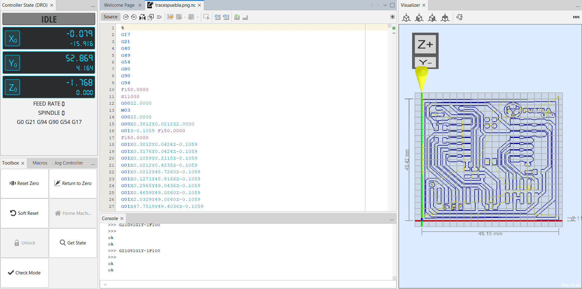
It is important that we "zero" the starting point of our cut, in this case, it is gonna be on the bottom left corner of our laminate. This is because the machine I´m using starts cutting up.
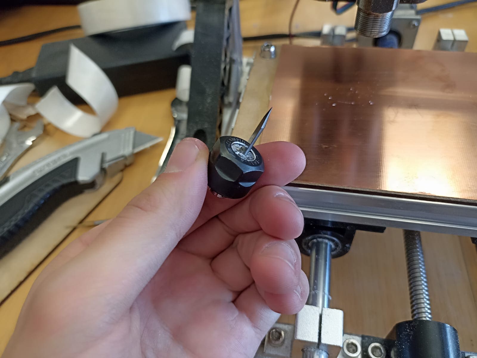
Also: the drillbit. We will be using 2 kinds: a 1/64" pointed drillbit for the engraving itself, and then a 1/32" round drillbit to cut the outter border of the plate
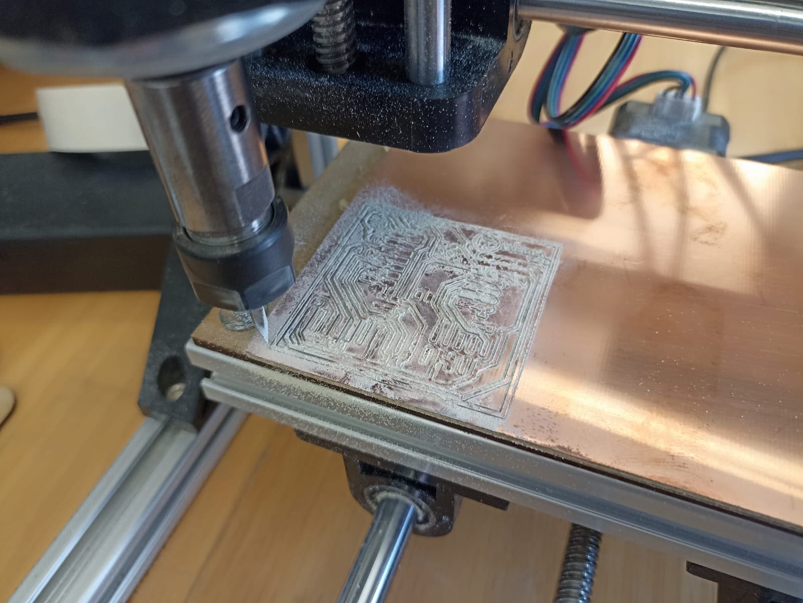
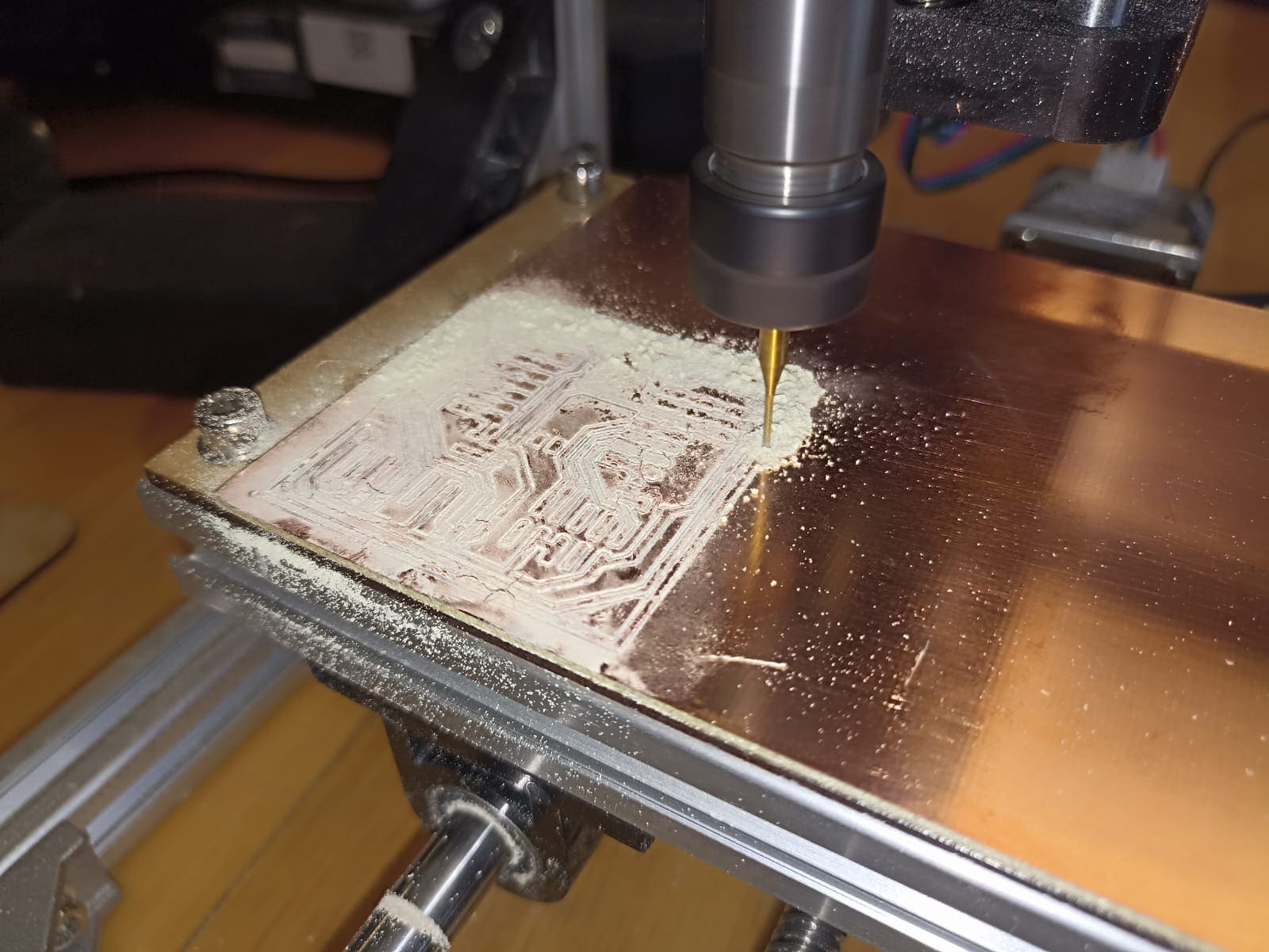
When everything is set and done, can start cutting :)
VERY IMPORTANT!: Do not breathe the dust coming off the plate, this is glass fiber dust, a strong irritant of the respiratory system, they also told me it could be carcinogenic. Don´t know if that is actually true, but I much rather not find out, neither should you. No need to panic, just stay away from the machine when cutting, vaccum the dust after, and cover your face if you have to get near :)

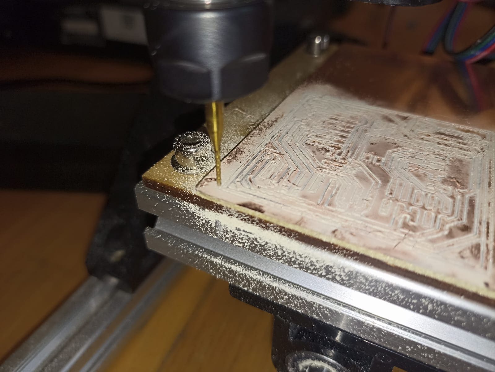
This is how the engraving should look like, well, kind of. I believe I calibrated the machine inaccurately because the tracks are cut in a very rough way, at least compared to some classmates´ work. Either that or the drillbit was not the adequate one. It should work just fine, but it´s not pleasantly looking and the soldering part will be thougher.
Now, we add the 1/32" drillbit and begin cutting the outter border
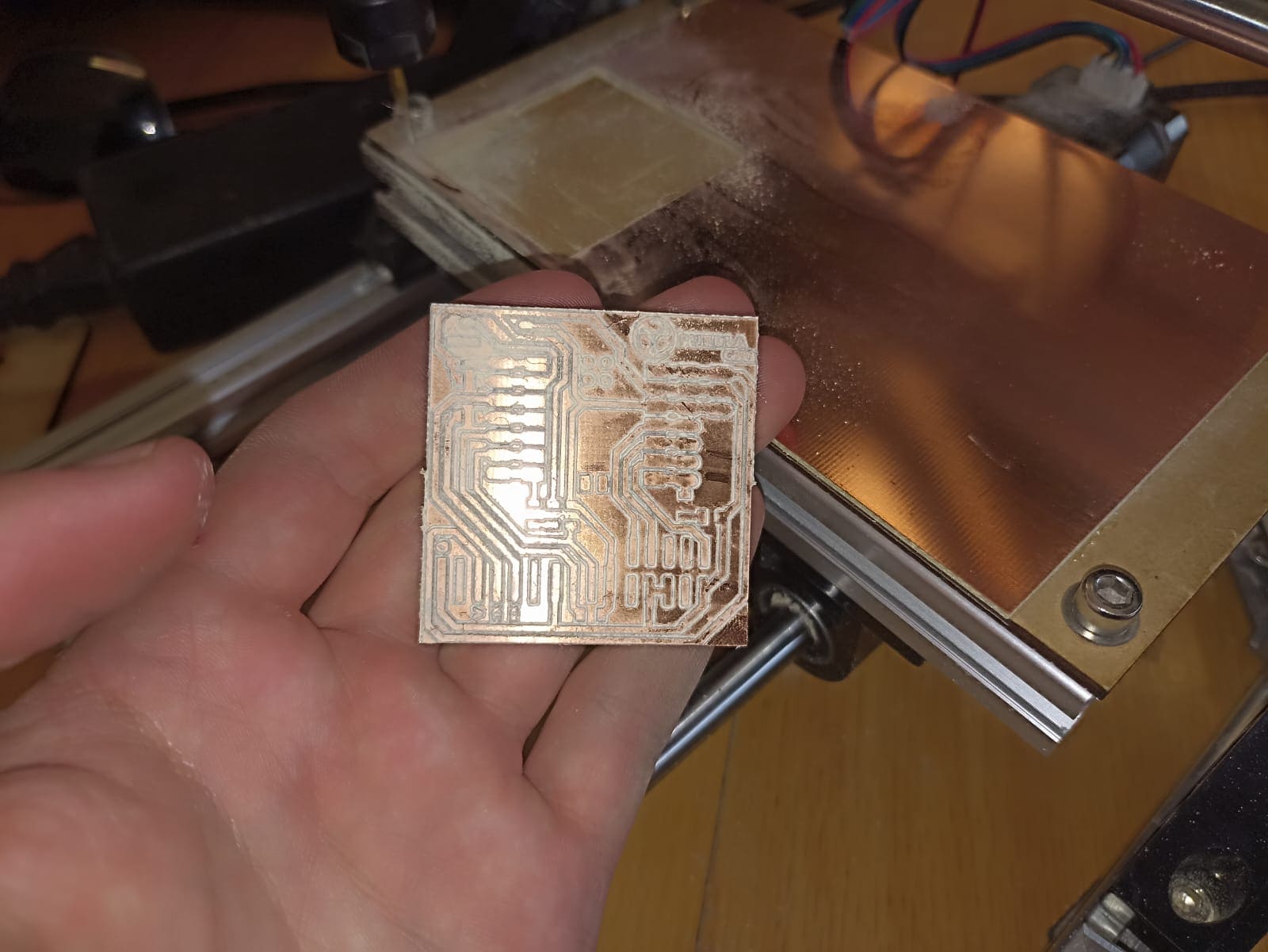
After we take out the cut section, we have our PCB looking like this:
Da Code
Let´s quickly take a look at how we are going to program this PCB, and generally the ESP32. It will be with good ol´ trusty arduino. You can download it according to your operating system using this link: Arduino Download
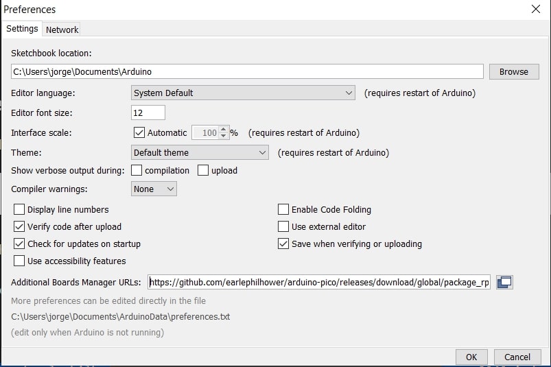
Once we have it installed, we need to add the Seeed Studio XIAO RP2040 board package:
Navigate to File > Preferences, and fill Additional Boards Manager URLs with the url: https://github.com/earlephilhower/arduino-pico/releases/download/global/package_rp2040_index.json
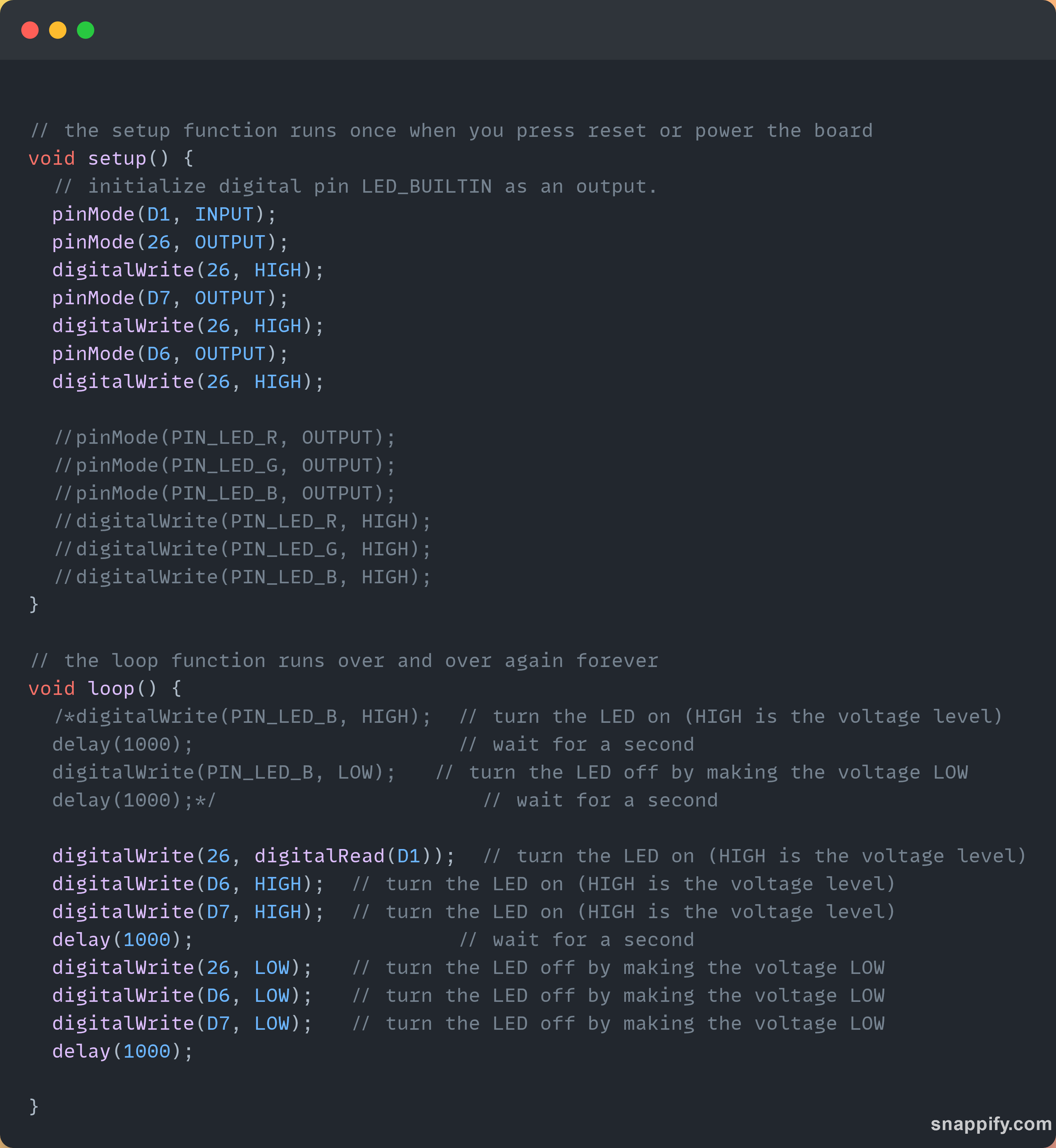
For the code, it will be a simple blinker using the LEDs we added to the PCB
Soldering that feels like nanotech
For the soldering part, I will be guiding myself using this diagram of the circuit, and the image of an example PCB made by our professors:
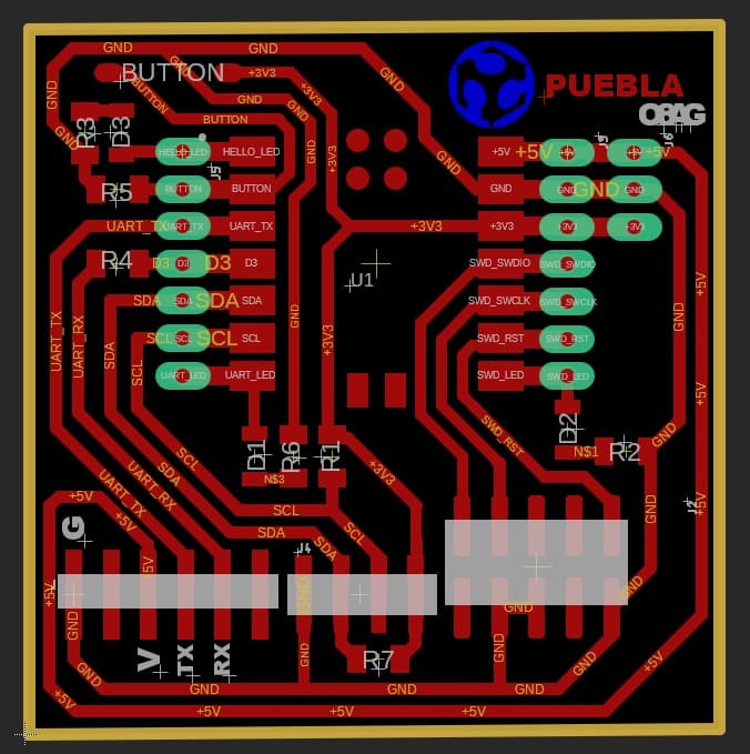
Also important to mention: the components in this PCB will be surface mount, as seen in the picture
The components for the PCB will be the following:
- XIAOESP32C3
- 6-1K ohm resistors
- 3 LEDS
- 1 Push Button
- 20 Pin Headers
- Solder and Soldlering iron
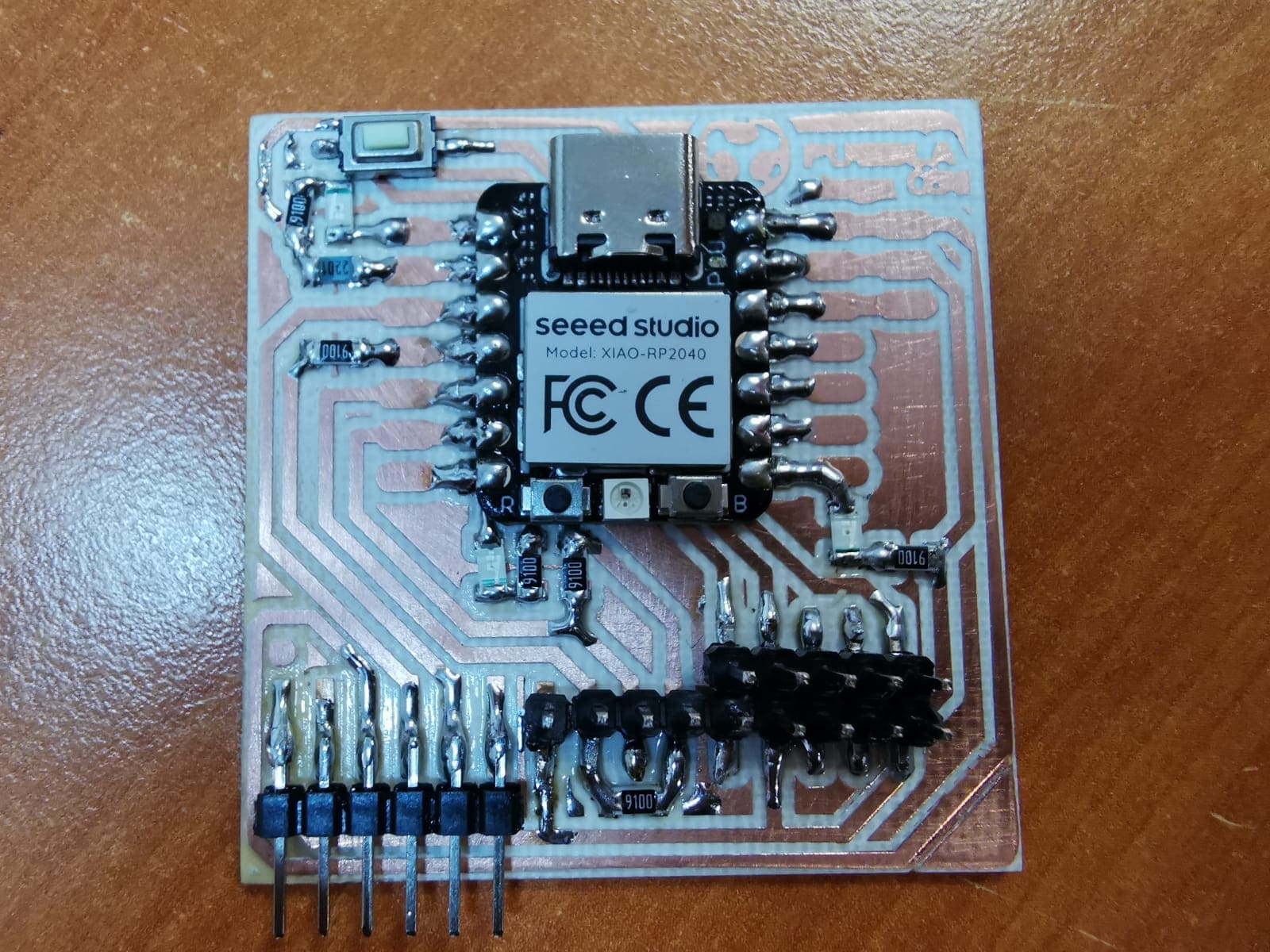
And so we begin to solder:
I could not capture in my camera my general idea of soldering, and even if I could I don´t think I did a good job at it. But my understanding of soldering the small surface mount components was adding solder to the contact points in the board, laying the component on top, and heat the solder from a side to have it melt around the contacts of the component. I don´t think I did a good at it since I got solder on tracks that I should not have, added more solder to joints that it was necessary, and even some made some short circuits between components. It was definitely not a textbook example of how to solder, but it got the job done, somewhat...
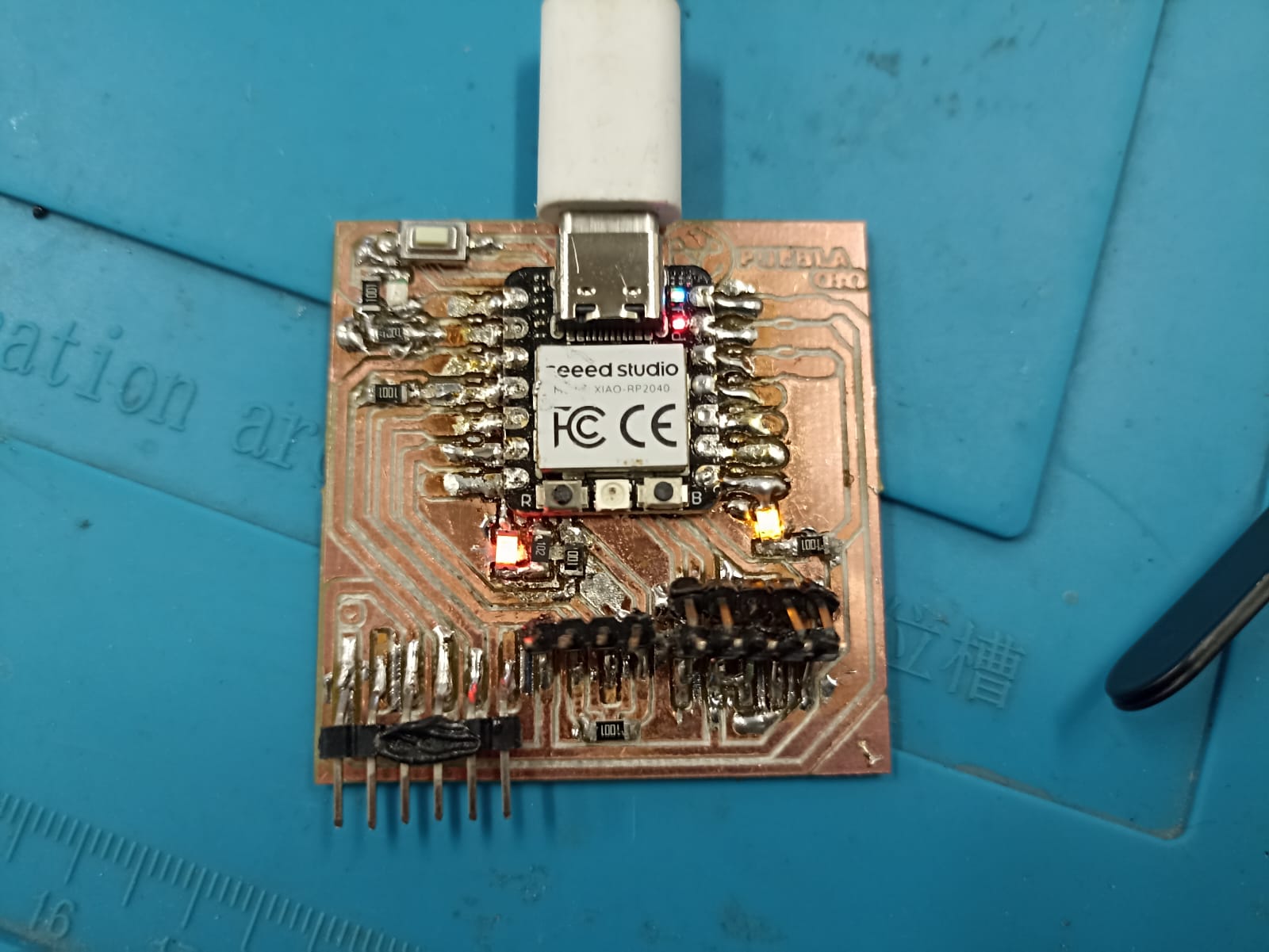
So, it turns out I missed a key part of this PCB, and generally some good advice when adding surface mount components to a exposed track PCB; adding electrical tape to the bottom of the XIAO to avoid short circuits. Turns out this component has exposed terminals on it´s bottom side that can make contact with the exposed tracks. Unfortunately for me, that exact thing happened and the moment I connected the PCB to my laptop the LEDs flashed and turned off immediatly. On the brightside, this board probably has short circuit protection, meaning it shuts down when it detects a short circuit preventing the board from burning. So what I had to do was desolder the XIAO (and some poorly soldered resistors), added the electrical tape beneath, solder again and hope for the best.
.... Let´s try again, shall we?
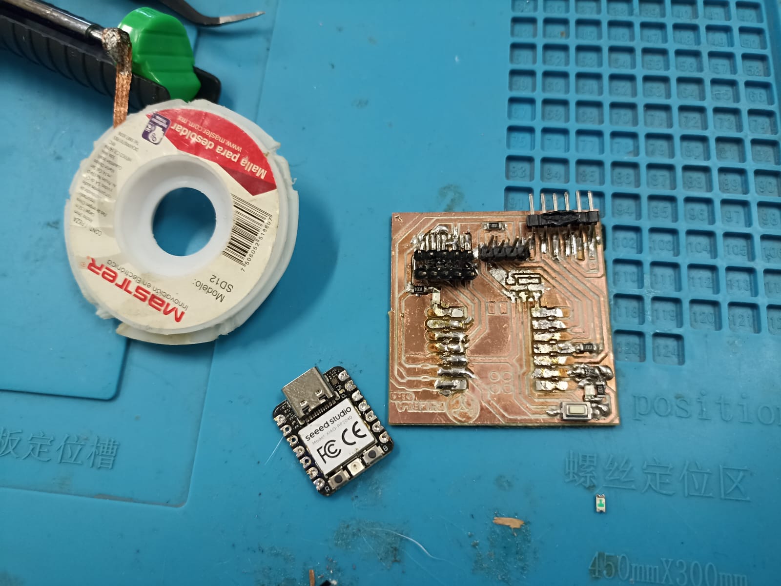
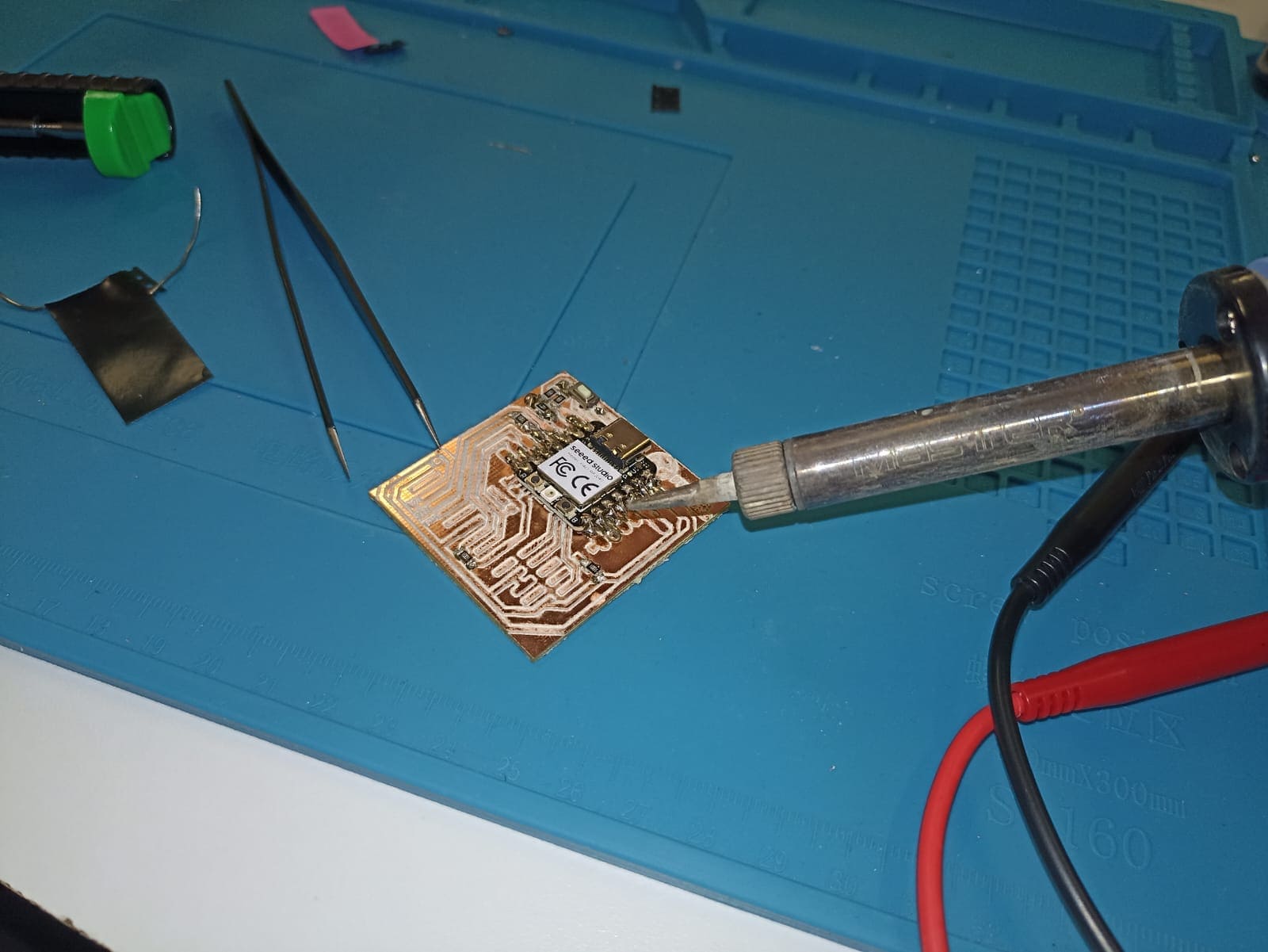
As you can see in the photo, I used a lot of desoldering wick to take all the solder from beneath the board and to clean any excess that could be causing the short circuit
After some tense moments, turns out the board was working just fine and it turns out I just had very poor soldering skills
Blinking LEDs: