Final project: Project A.M.E.C.

Slide Presentation
Video Presentation
What is it?
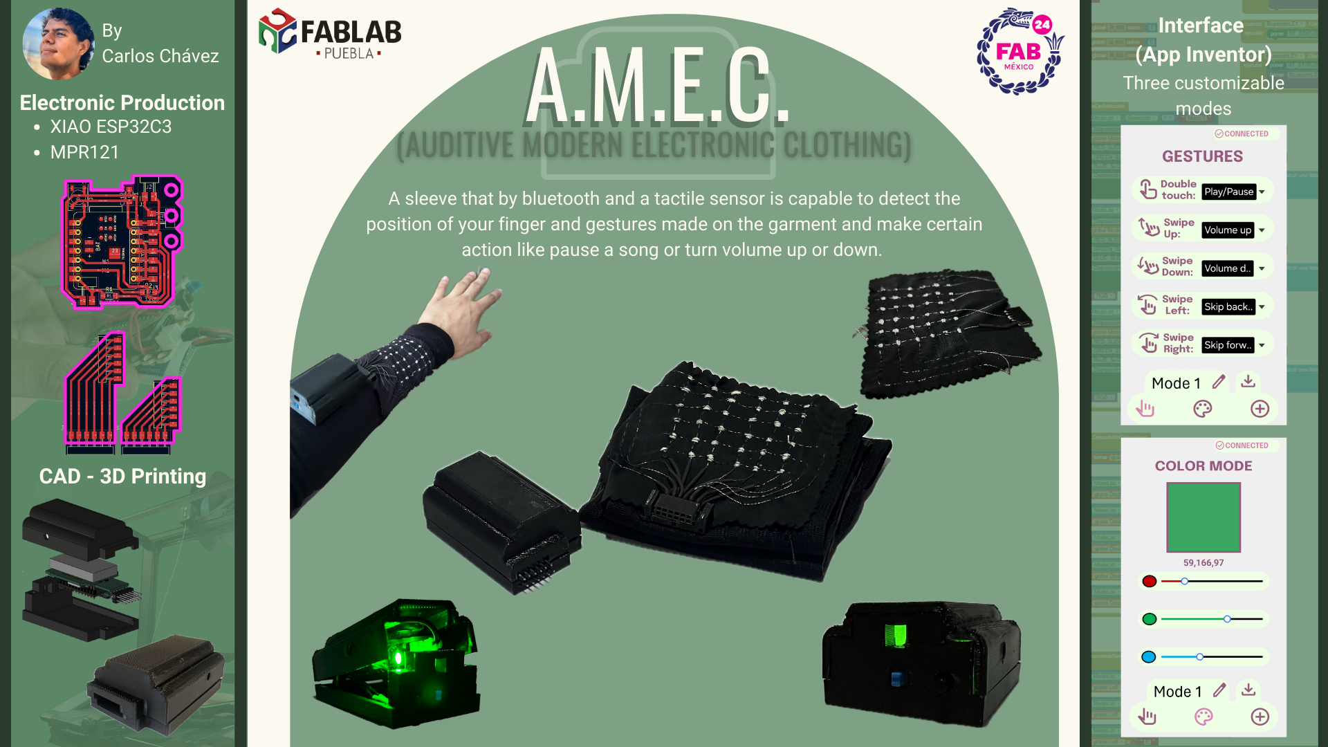
The idea of the project A.M.E.C. (Auditive Modern Electronic Clothing) is to create tech-clothe that by bluetooth and a tactil sensor be capable to make the same tasks that a smartwatch does answer calls or control the music you are listening to.
Characteristics
Connectivity: Connected to your phone via bluetooth
Tactil sensor: A tactil sensor to answer calls, control your music.
 How is it going to work?
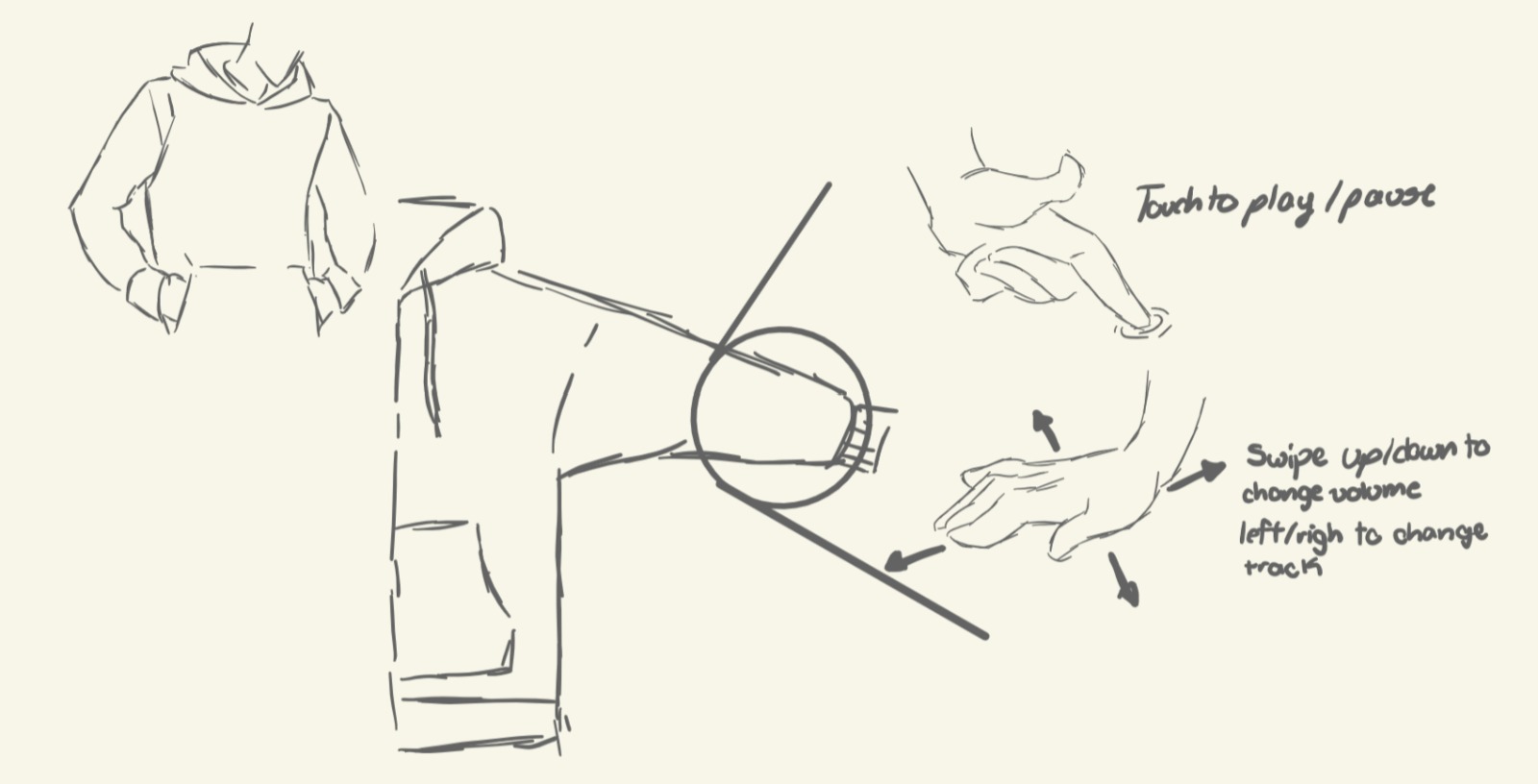
The way the hoodie will know what gesture you are doing is by using a touchpad sensor made of conductive thread. The touchpad will send the positions of your finger to the PCB and, the PCB, will interpret those position and will know what gesture it is. The PCB will be placed on the arm and it will be easily removable so it can be charge.
What will it do?
By using conductive threas will detect the positions of your finger and using that information will know what kind of gestures the user is doing. With this gestures the user can make certain actions like change the song, turn up or down the volume, accept calls, etc.
WorkFlow
To have an order on this project I decided to make a cronogram with all the tasks I have to do, it starts on January 24th with the creation of the sketch and final project page, and it is planned to end on June 8th with the creation of the Slide and Video for the presentation.
I also decided to make a calendar to show the exact day when I make the individual tasks. You can click on the task to see what exactly a did on that day.
| Sun | Mon | Tue | Wed | Thu | Fri | Sat |
|---|
Previous Works
 Project Jacquard
Google's Advanced Technology and Projects group (ATAP) created a project called "Jacquard". The idea of the project seeks to create smart garments capable of performing the same actions as a smart watch but unfortunately, Google shut down the project for unkown reasons. The only launched a jacket in collaboration with Levis.
Madison Maxey
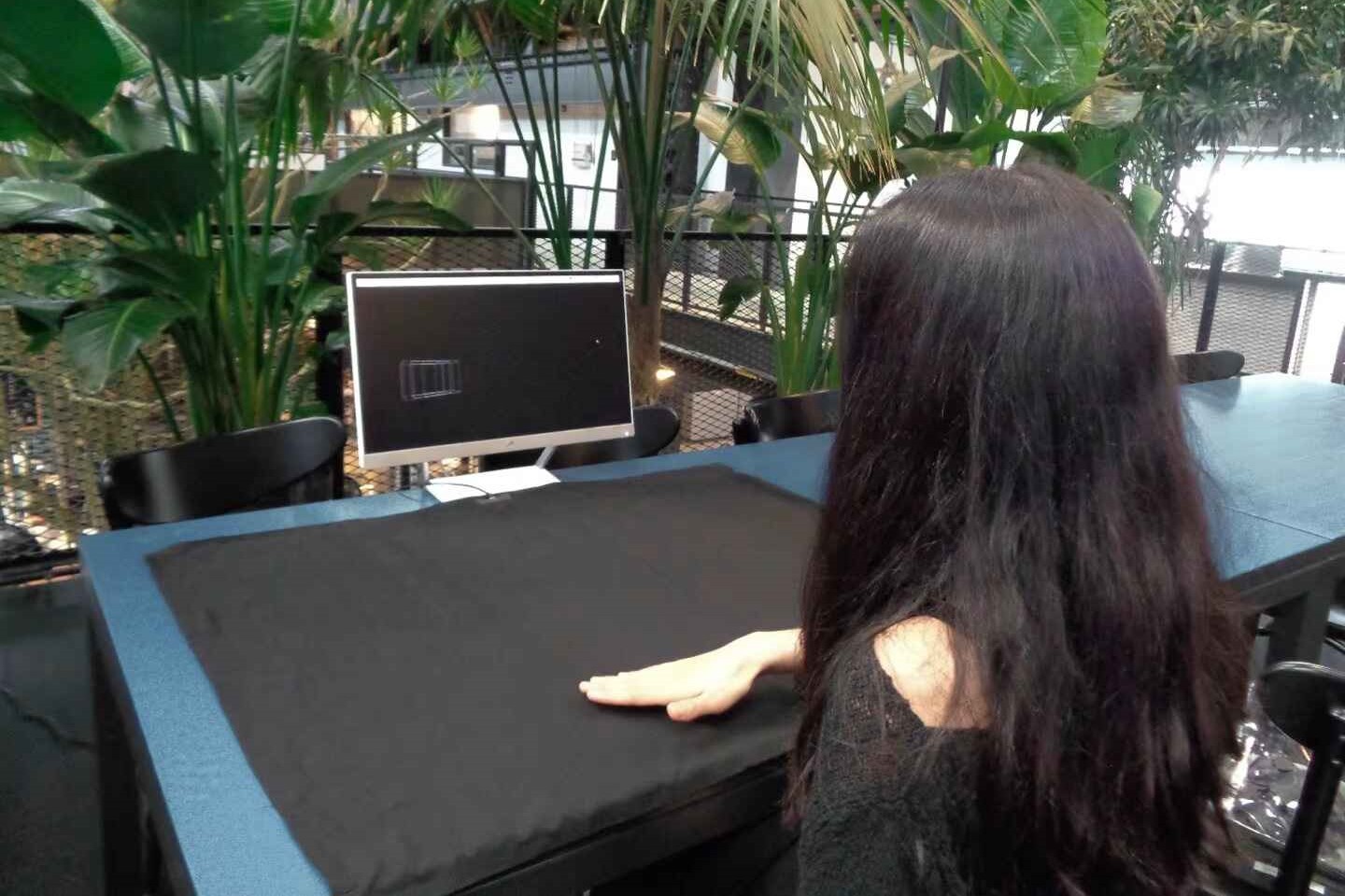 Masison Maxey, the CEO and founder of Loomia, devoled a proof of concept for a foldable, drapable, large surface area capacitive touch textile using an
Adafruit Flora microcontroller. The idea is a large user interface that can be folded and carried for creative work. This Textile trackpad can be used
to replace a computer mouse and could also be used to model, sketch and draw in the computer.
Masison Maxey, the CEO and founder of Loomia, devoled a proof of concept for a foldable, drapable, large surface area capacitive touch textile using an
Adafruit Flora microcontroller. The idea is a large user interface that can be folded and carried for creative work. This Textile trackpad can be used
to replace a computer mouse and could also be used to model, sketch and draw in the computer.
Materials
| Material | Qty | Price (Dollars) | Link |
|---|---|---|---|
| XIAO ESP32C3 | 1 | $20.02 | Buy Here! |
| MPR121 | 1 | $5.82 ea. | Buy Here! |
| Conductive Thread | 1 | $18.16 | Buy Here! |
| Male Pin Header | 12 | $13.55 | Buy Here! |
| Female Pin Header | 12 | $9.95 | Buy Here! |
| Push Button | 1 | $0.16 | Buy Here! |
| Switch button | 1 | $0.33 ea. | Buy Here! |
| NeoPixel WS2812B | 1 | $0.49 | Buy Here! |
| Magnets | 6 | $0.081 ea. | Buy Here! |
| Athletic Sleeve | 1 | $10.92 | Buy Here! |
| 3.7V Lipo Battery | 1 | $4.31 | Buy Here! |
| Total: $84.196 |
MPR121 TEST
Before starting the project I have to cheeck if the MPR121 Module will workm to do this .
Matrix
I had to know how to make the matrix in order to test if the sensor was going to work. To do this I started with a prototype made with masking tape copper tape.
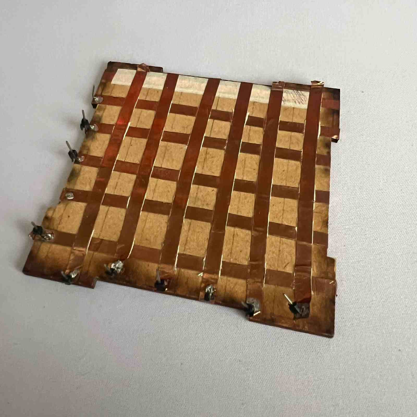
The idea is simple, first you paste the copper tape stripes in one direction, then you cover it with masking tape (this will prevent the tapes of both direction from being in contact) and place the opposite direction copper in top. Finally you will have to cut the excess of the masking tape.
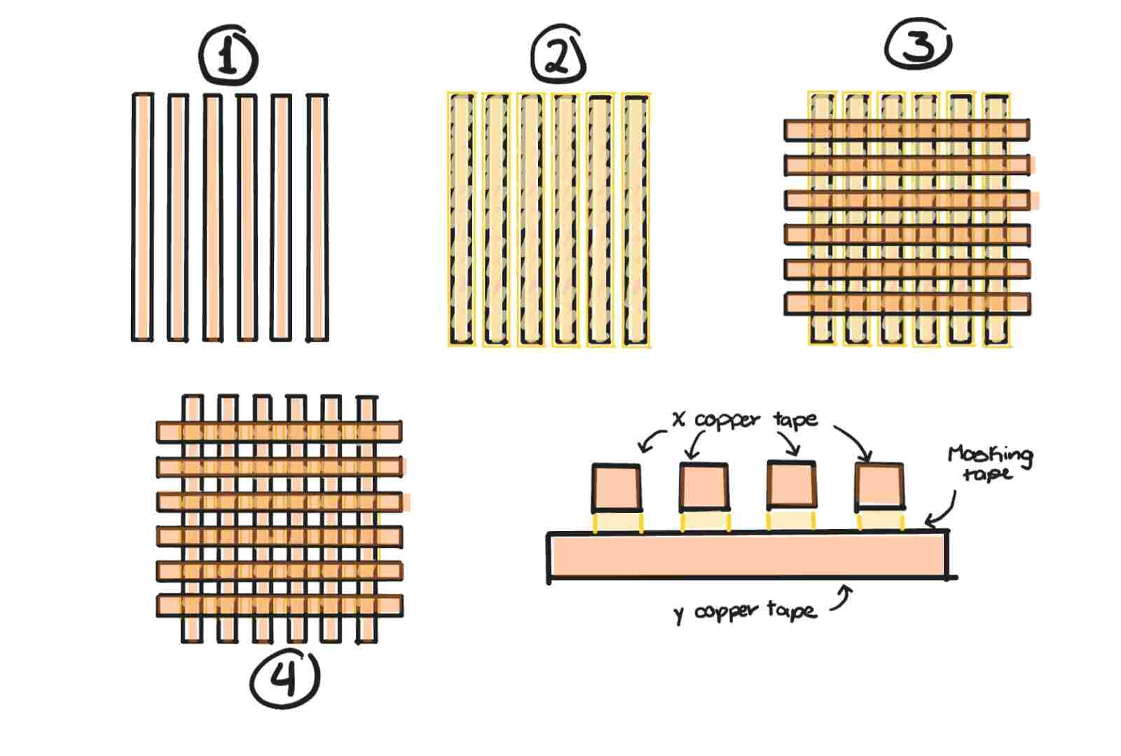
This will prevent the copper tapes to touch between them but when you put your finger in it, beacuse the size of the finger is bigger, will touch both and I will know which row and columm is being touch.
Code
With the prototype done it was time to test the module, I made the following code to test it:
	#include < Wire.h > //Library to communicate with I2C
	#include < Adafruit_MPR121.h > //Library of the MPR121 module

	// Create the sensor object
	Adafruit_MPR121 cap = Adafruit_MPR121();

	int X_Position = 0;  // Track the value of x position
	int Y_Position = 0;  // Track the value of y position

	void setup() {
		Serial.begin(9600);

		// Initialize the sensor
		if (!cap.begin(0x5A)) {  // Default I2C address for MPR121 is 0x5A
			while (1);
		}
	}

	void loop() {
		// Get the currently touched pads
		int touched = cap.touched();

		// Reset x and y positions
		X_Position = 0;
		Y_Position = 0;

		// Check each pad to see if it is currently touched
		for (int i = 0; i < 12; i++) {
			if (touched & (1 << i)) {
				if (i < 6) {  // Pins 0-5
					X_Position = i + 1;  // Save the position (1-based)
				}
				else {  // Pins 6-11
					Y_Position = (i - 6) + 1;  // Save the position (1-based)
				}
			}
		}

		// Print the status of x and y positions
		Serial.print("X Position: ");
		Serial.print(X_Position);
		Serial.print("  -   Y Position: ");
		Serial.println(Y_Position);

		delay(100);  // Small delay to avoid flooding the serial output
	}
Final Result
PCBs Creation
To design my PCBs I used the software we learn on our week 8 assignment, KiCad. I used this software beacuse I am already familiar with it and beacuse I have almost all the components' footprints on it thanks to the libraries our local evaluators gave us.
microcontroller's PCB
Here is the Schematic of the microcontroller's PCB.

Microcontroller (XIAO ESP32C3)
As you can see, I only needed to connect a few thing to the XIAO.
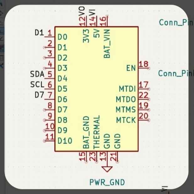
Vi pin: This is the pin that will reacieve the voltaje from the battery.
Vo pin: This pin will turned that voltaje in 3V, and will be directed to the Neopixel and the MPR121 module.
GND pin: This pin is the one connected to the ground from the battery.
D1 pin: This pin is the one connected to the NeoPixel.
D7 pin: This pin is the one connected to the Push Butten.
SDA and SCL pins:This pins come from the Xiao and will send the data to it via I2C communication.
MPR121 Module
The are the pins that I had to connect for the module.
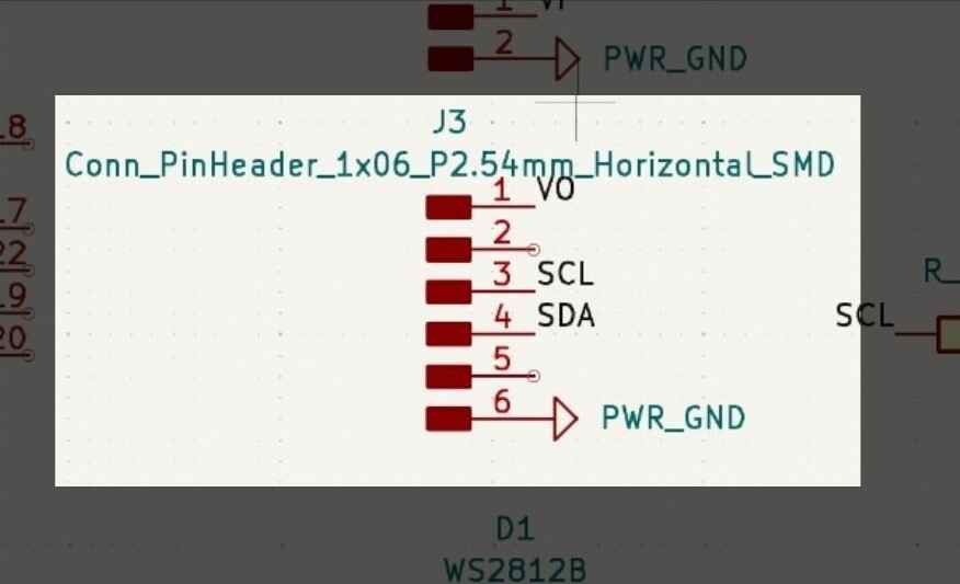
Vo pin: This pin will come from the Xiao beacuse the max voltaje that the MPR121 allows is 3.3V.
GND pin: This pin is the one connected to the ground from the battery.
SDA and SCL pins: This pins are connected to the MPR121 module, it is a I2C communication, so the module can send which pads are baing touch.
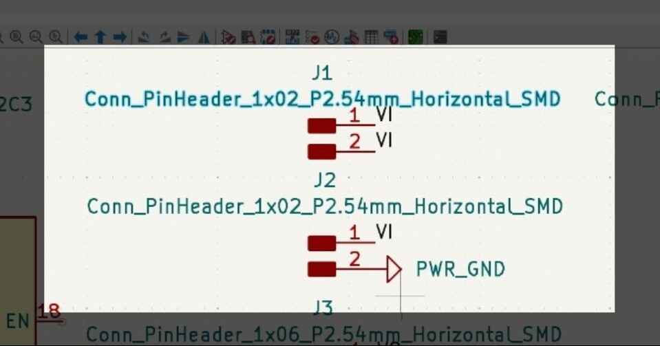
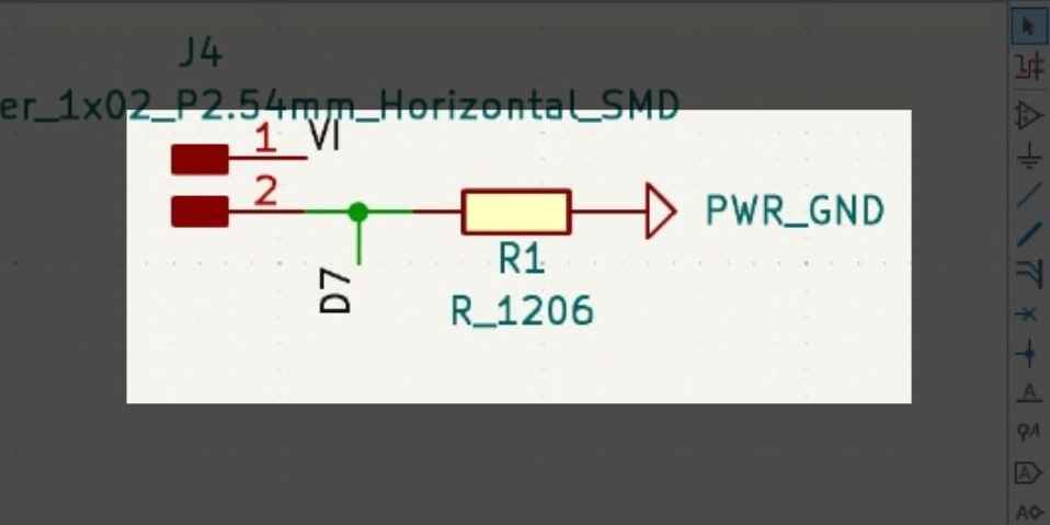
Voltajes pins
This are the voltaje pins and they will be connected to the battery and the switch button. The first two pins of the top are the ones connected to the switch button and their purpouse is to control if or not the voltaje from the battery to the Xiao.
The other two pins of the button are the ones that will be connected to the battery, one is for the voltaje and the other for the ground.
Button
Here is how I connect the button that will switch the different profiles that the device will have.
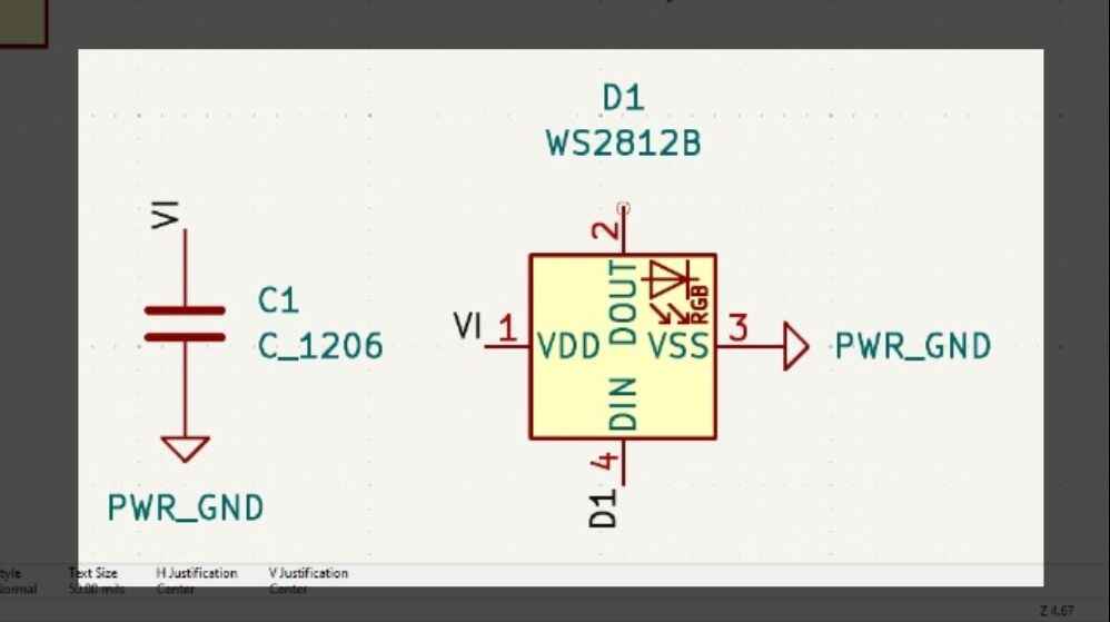
NeoPixel WS2812B
Here is how I connected the Neo Pixel that will show which profile is being use.
Extra
I had trouble connecting the things while design the PCB that why I will used a 0k Resister to use it as bridge.
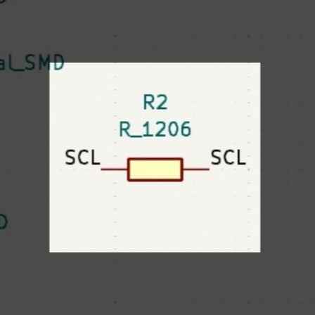
The designed of the PCB was something simple but complicated to connect beacuse I wanted to make it as small as possible.
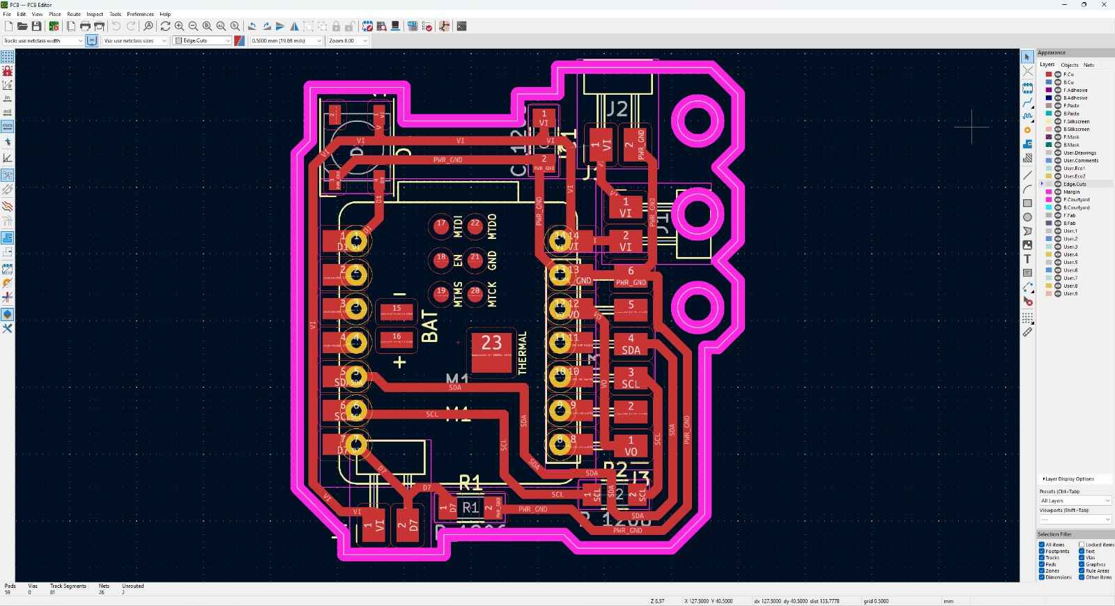
Finally I cut the PCB on the Mini-Mill
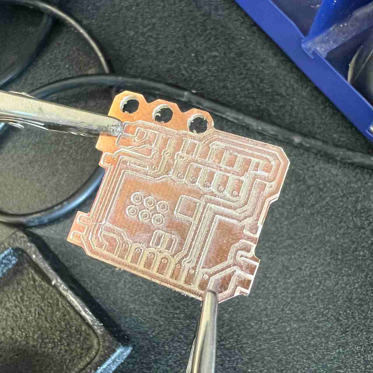
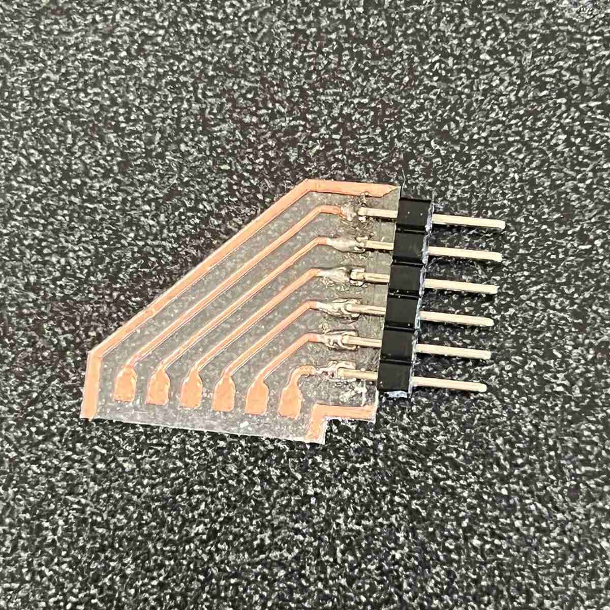
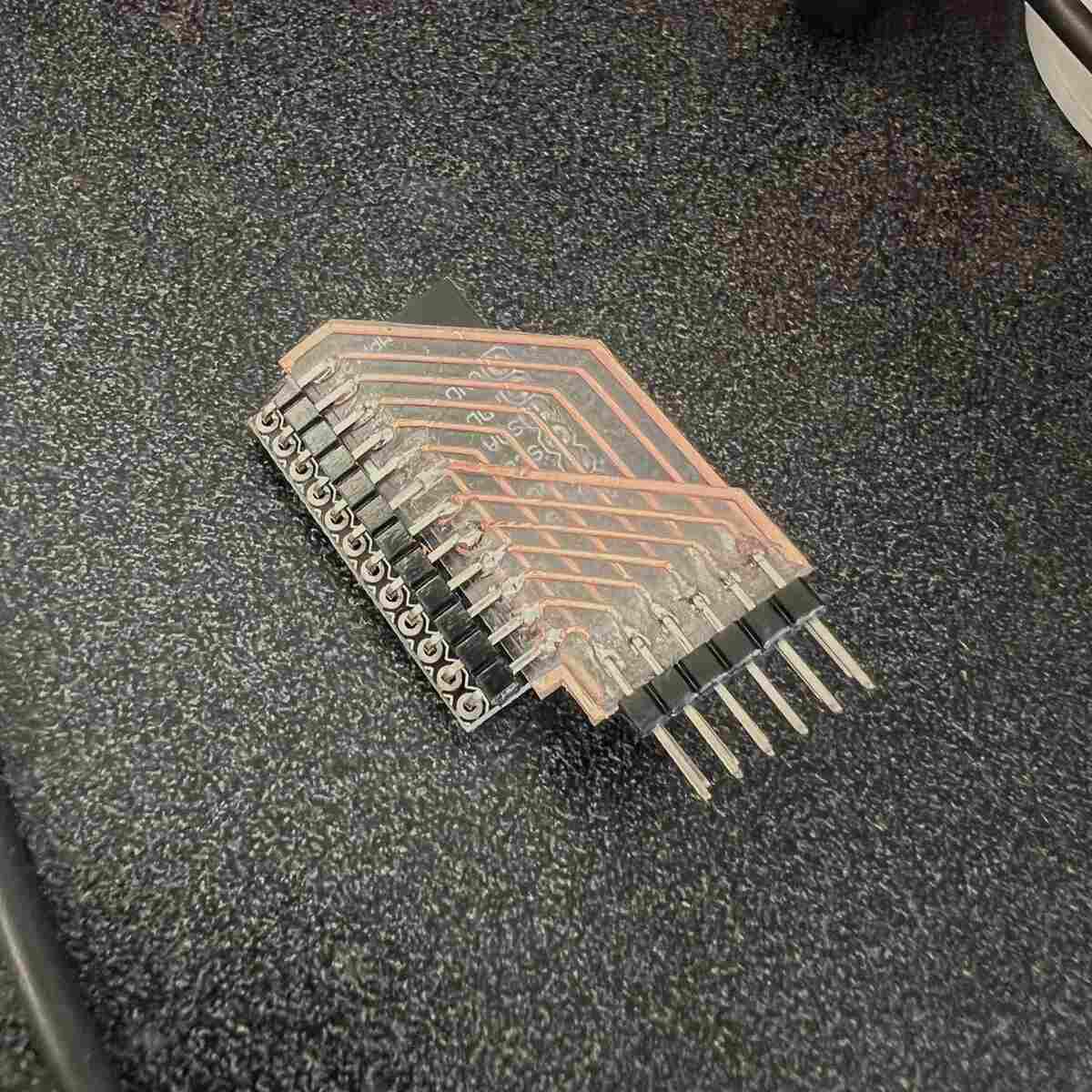
MPR121's PCB
I also had to design a PCB to change the direction of the touchpad pins of the module. Also I need to have 6 pins on top and 6 on the botton, thats why I made two.
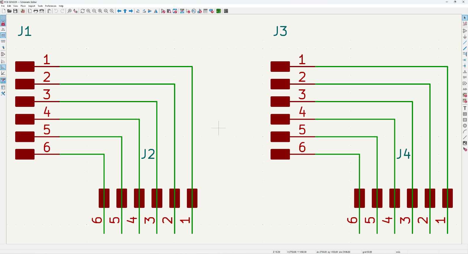
Here is the desing of these PCBs, as you can see the direction of the pins 90°.
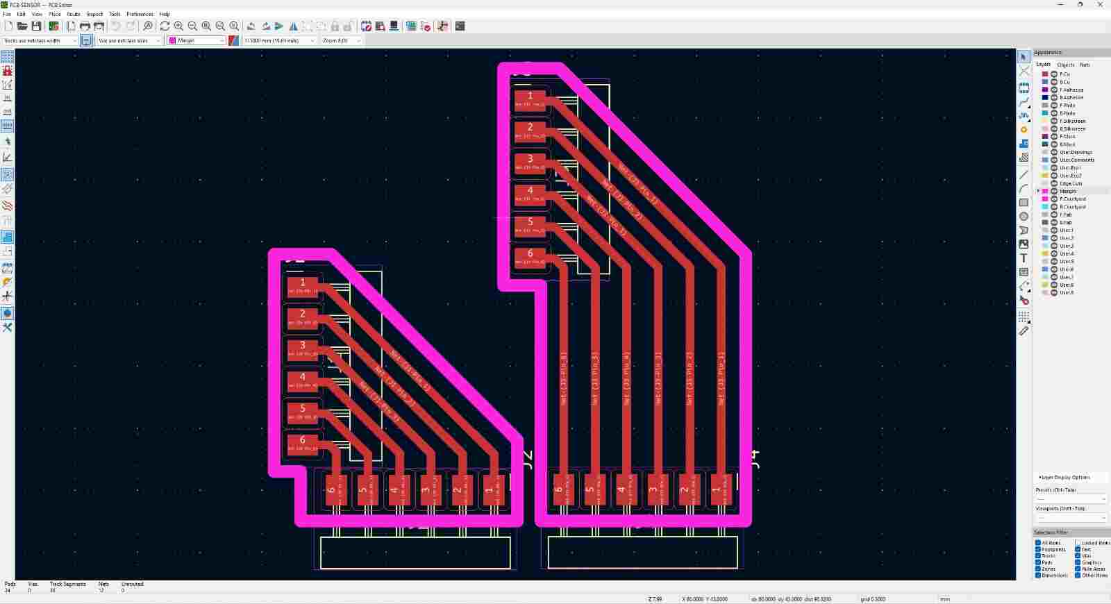
I needed to make them as small and thin as posible thats why I made them flexible.
Using some twizzers I took out the extra copper.
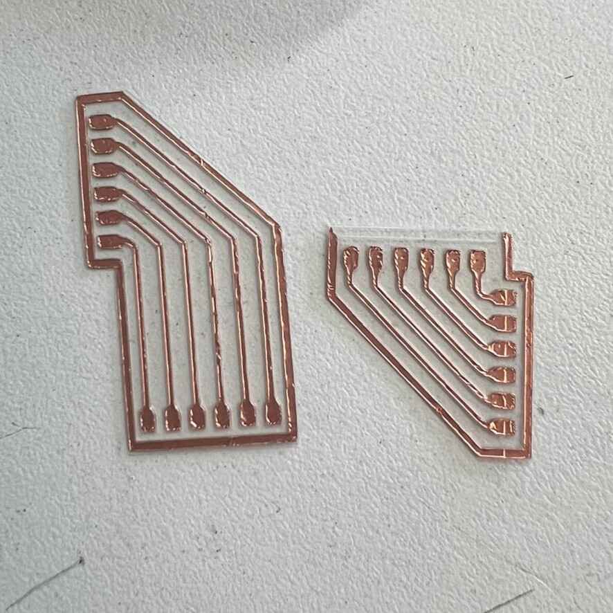
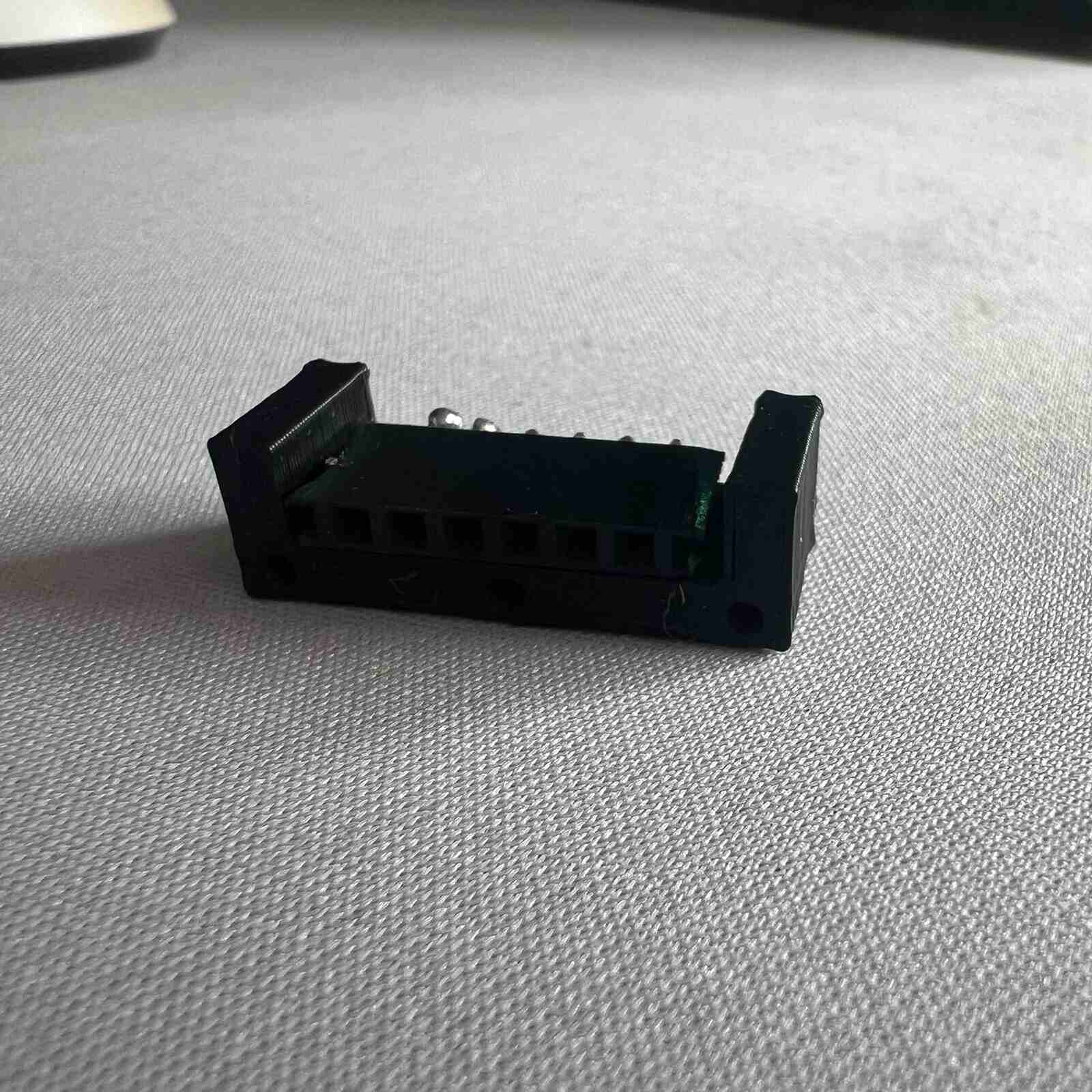
Finally I just solder to the pins and to the MPR121 Module.
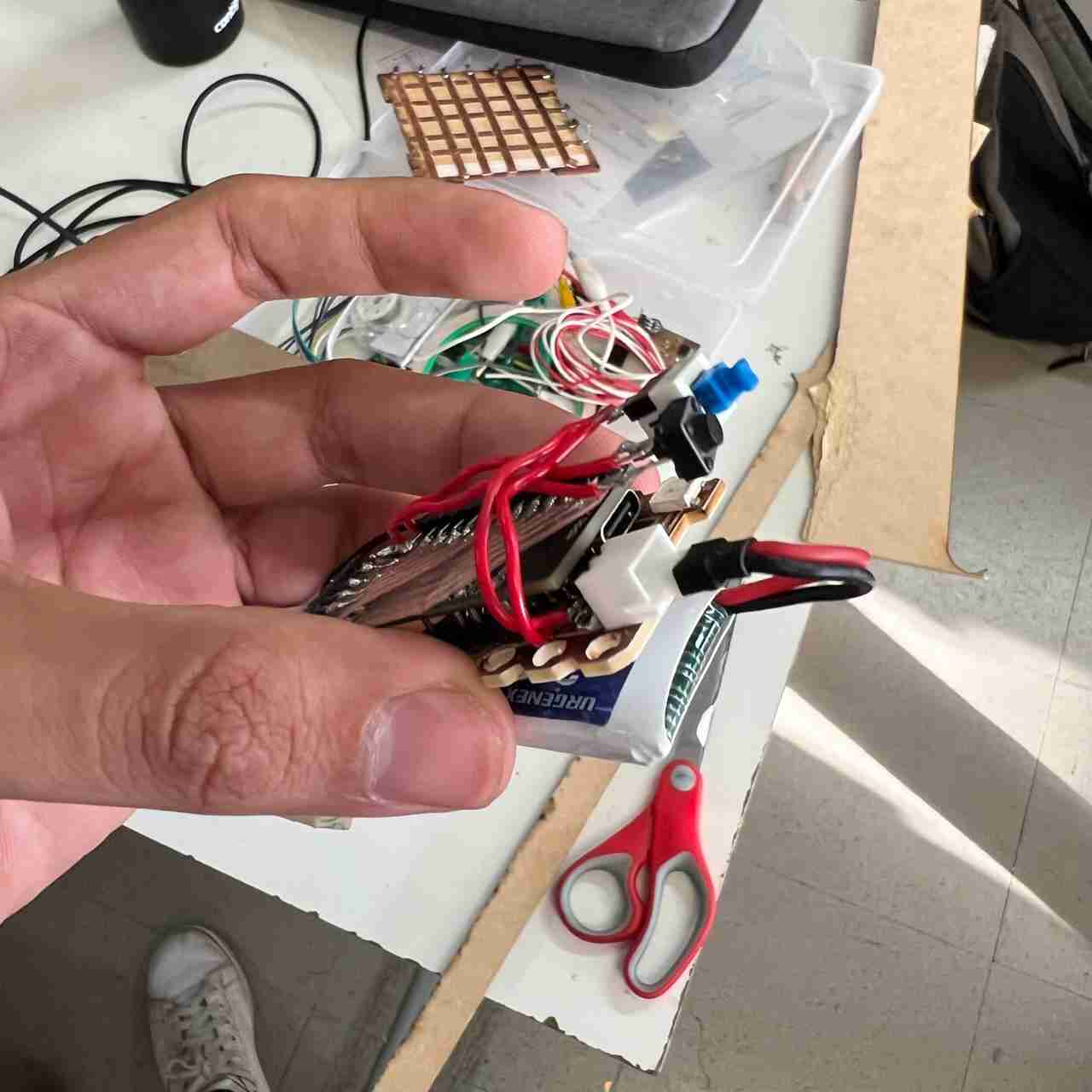
Here is the Final Result of the electonics.
You can find the files of the PCBs at the bottom the page on the File section.
Case Creation
Designing
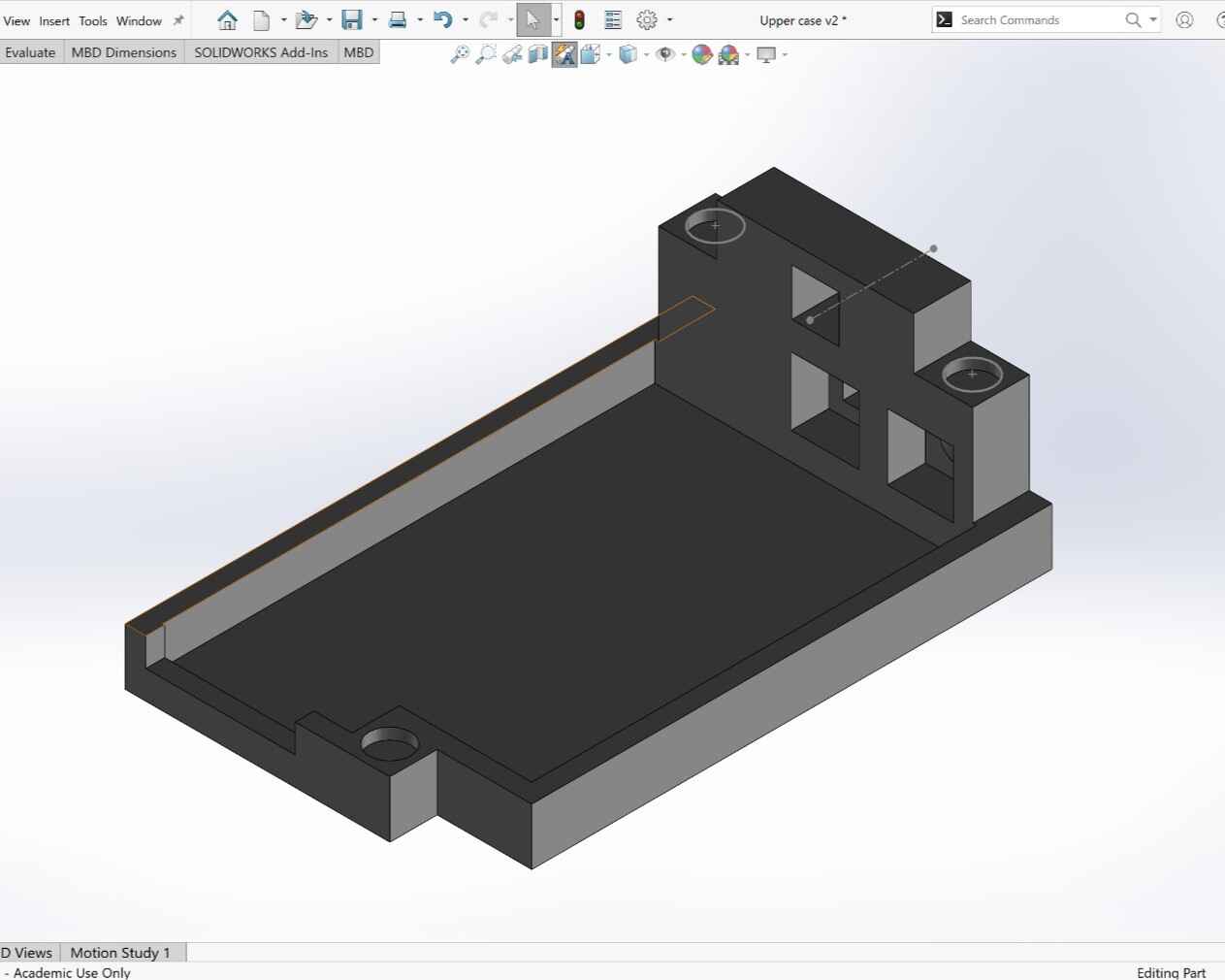
With the PCBs done the next thing I did was its case, to do this I used the software SolidWorkd because I am very familiar with it.
I needed to have in mind certain aspects when designing the case:
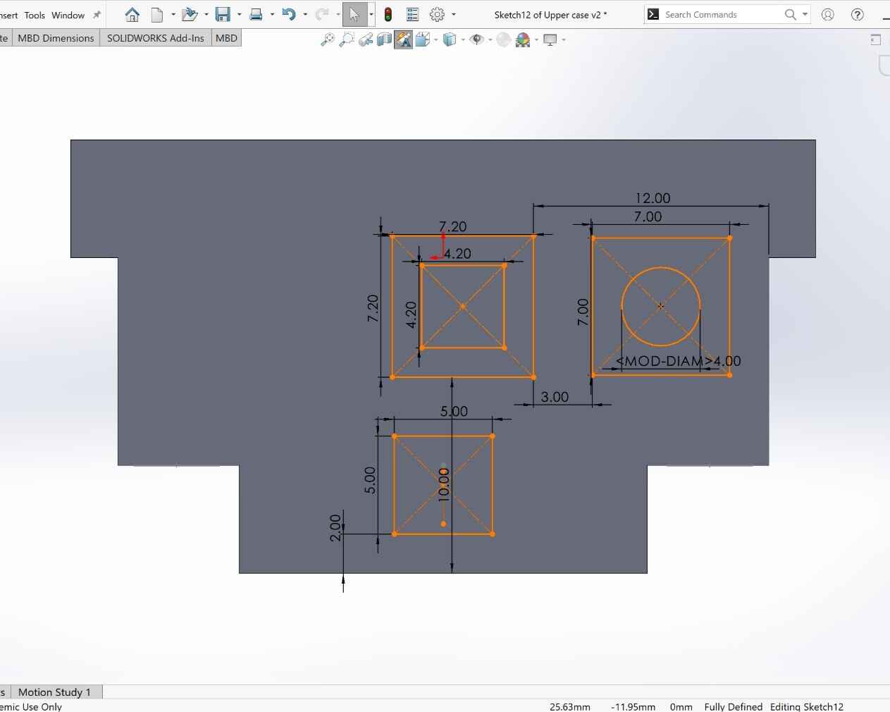
Try to make it small as possible
Make spaces for the different components (Neopixel, buttons and pins).
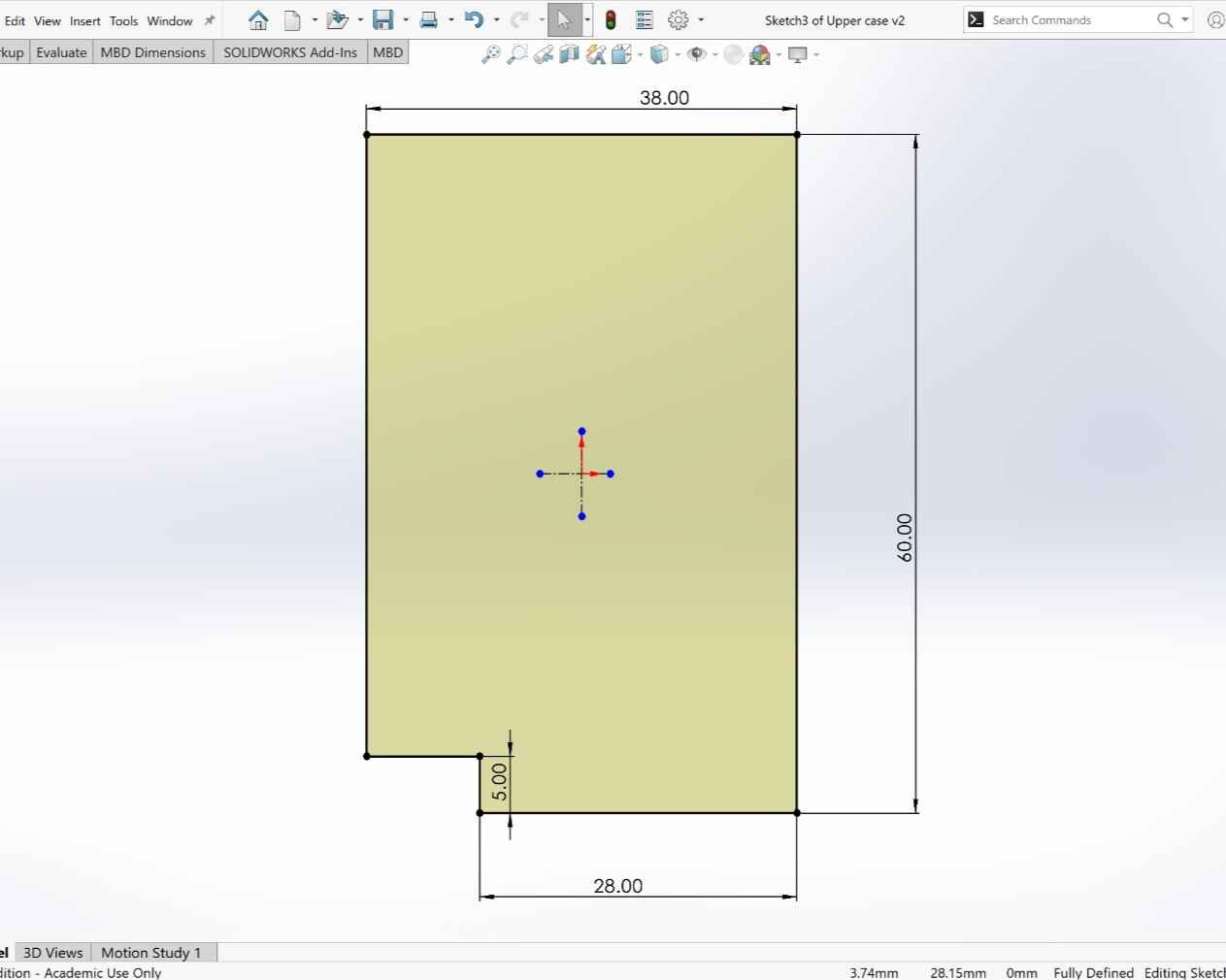
With this in mind I started designing the upper part of the case.
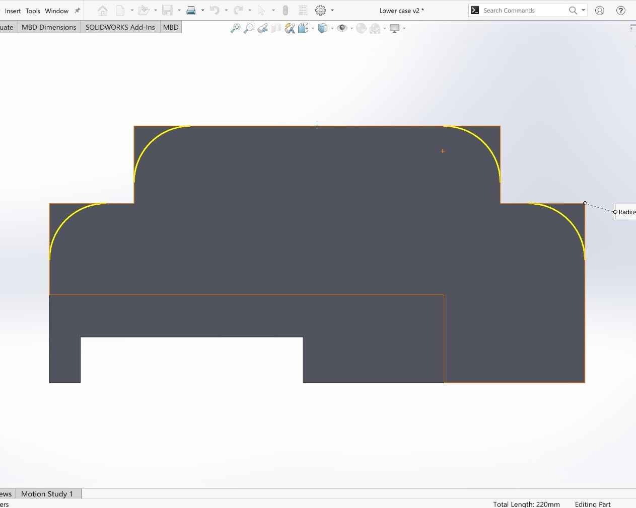
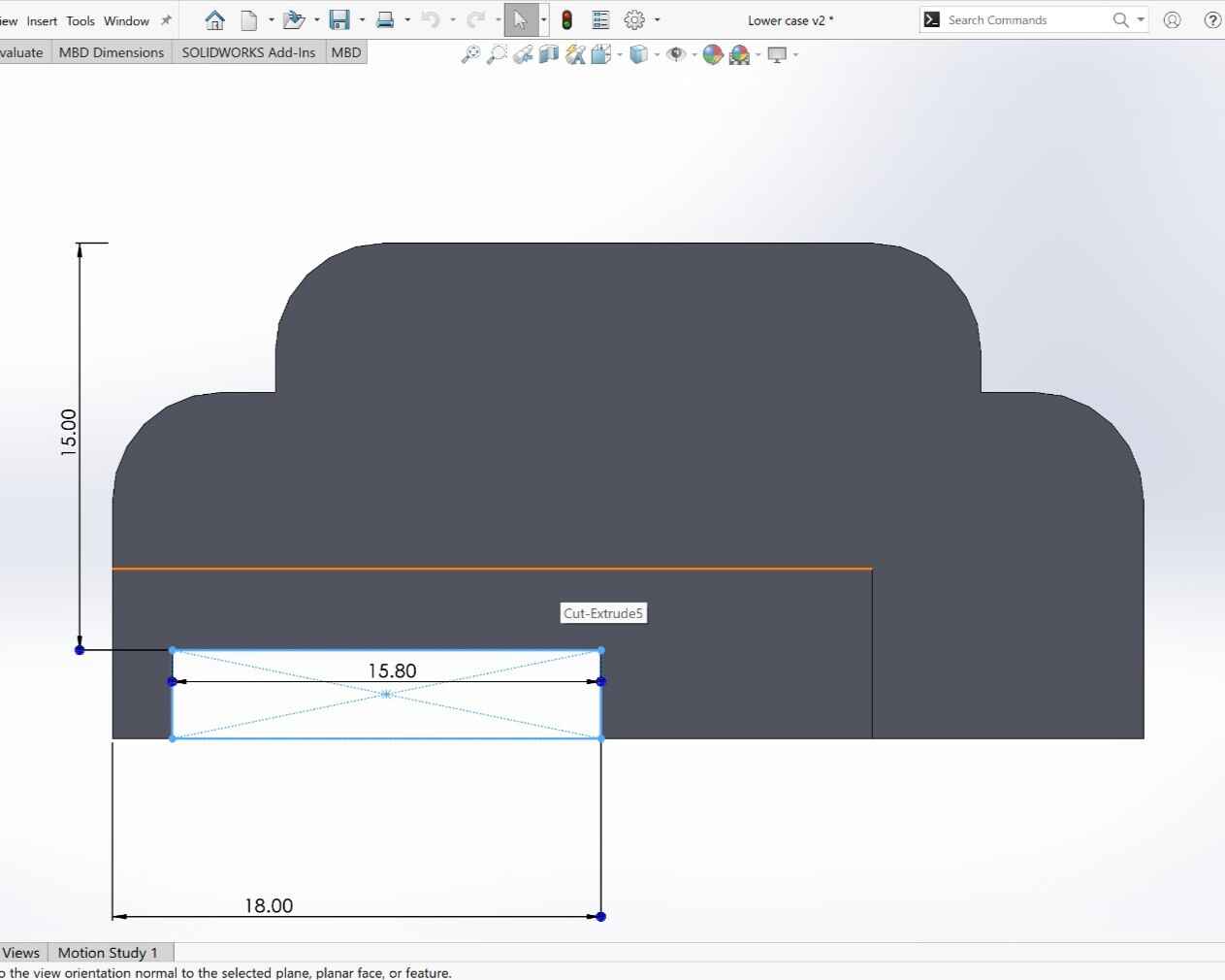
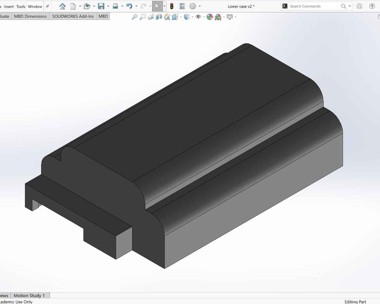
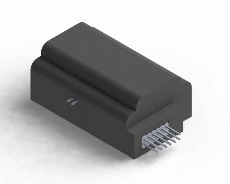
Then, I made the lower part of the case which contains the spaces for the buttons and neopixel.
Here is a render of the assembly.
With both parts designed I saved them as .stk files and used the software Cura to convert it in .gcode files.
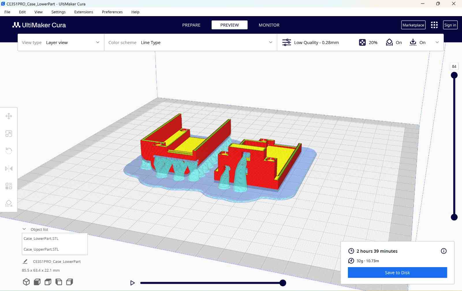
Printing
I used the Ender 3 S1 PRO to print the case.
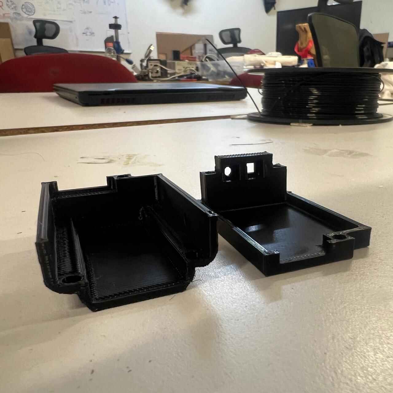
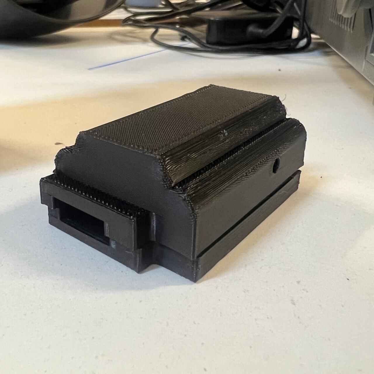
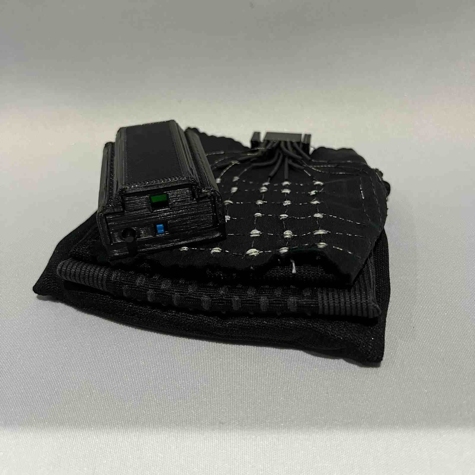
With the case printed, I juts put all the electronic inside and this si how it end up.
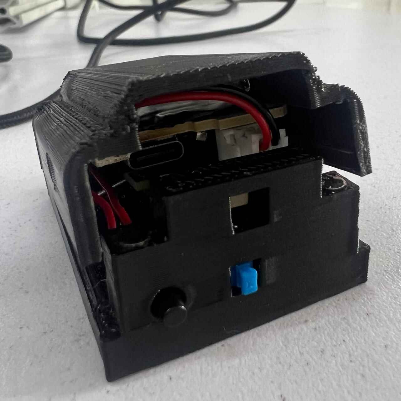
You can find the files of the PCB Case at the bottom the page on the File section.
Sleeve Creation
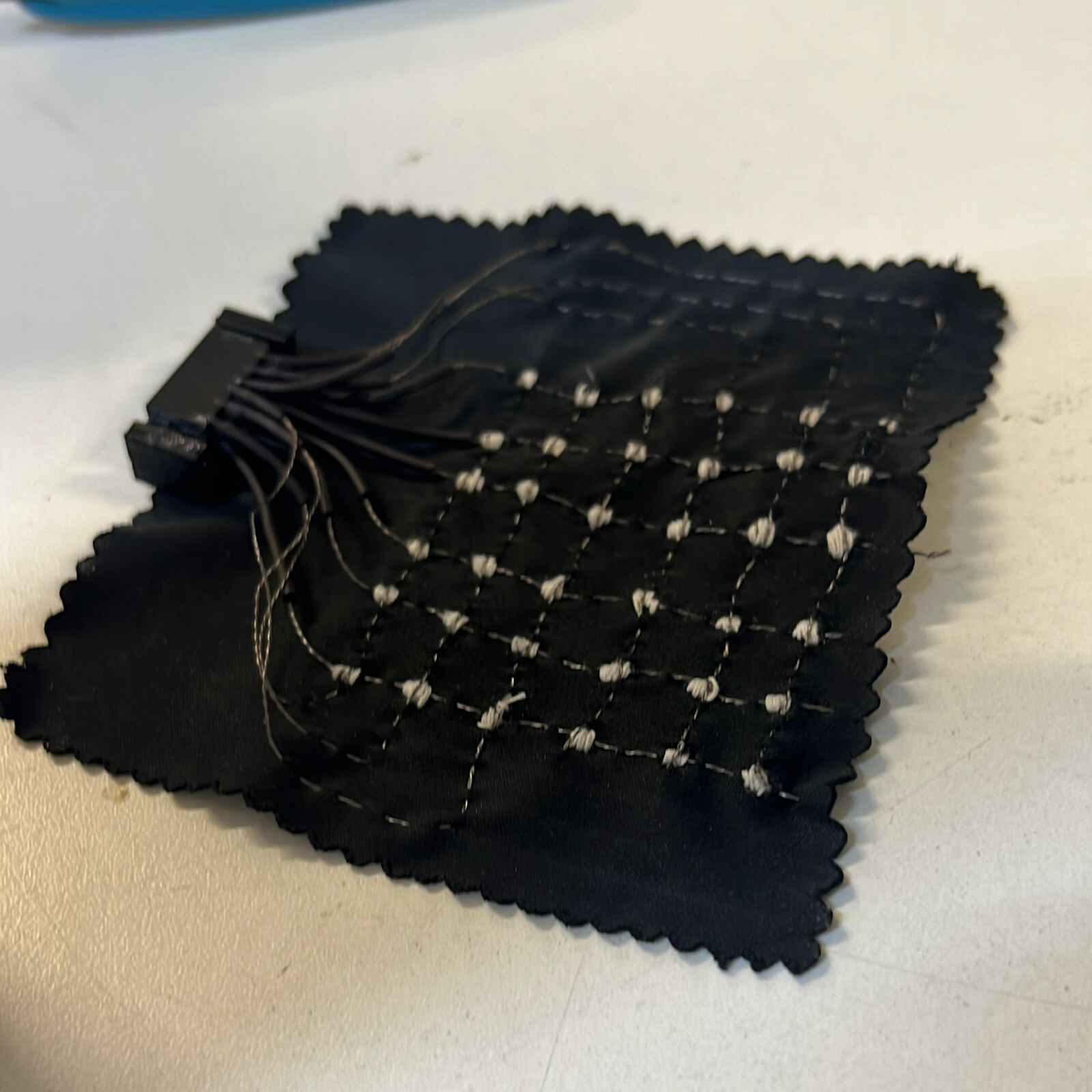
To create the sleeve that is going to detect the position and gestures of the finger I used an athletic sleeve as the main part, then I will laser cut a piece of clothe in which I am going to make the matrix with the conductive thread.
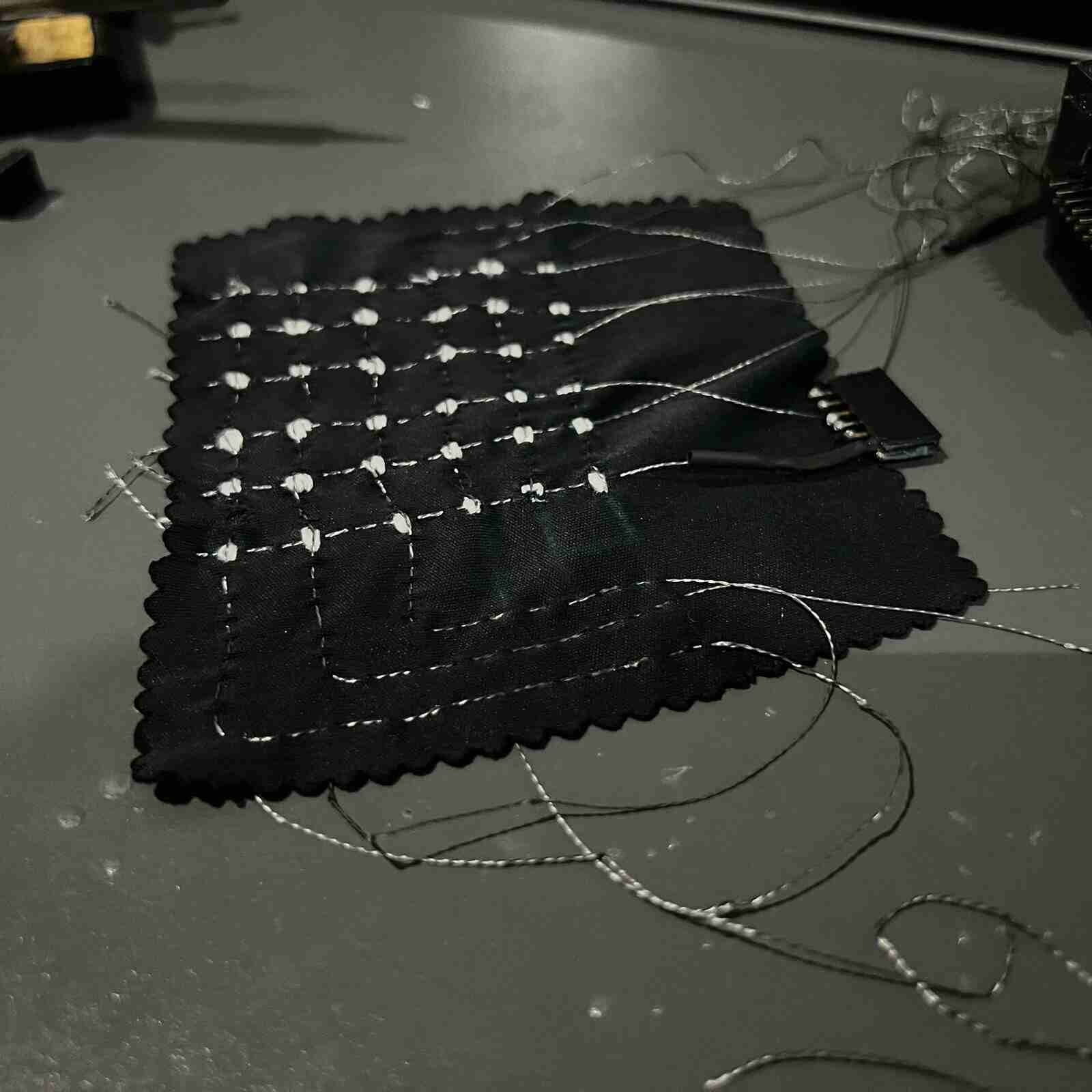
I also need to make the 3d parts that will support pins.
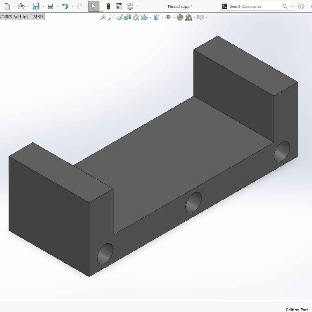
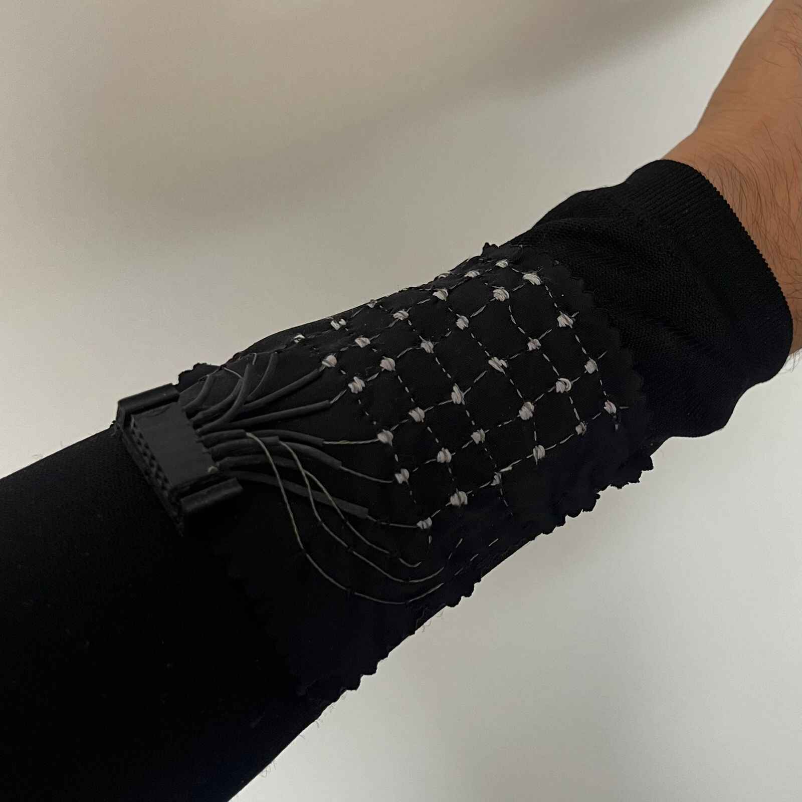
With the matrix and 3d part done I just sewed them all in the sleeve.
You can find the file of the pin support at the bottom the page on the File section.
App Creation
To create the app I used the MIT App Inventor page beacuse I am already familiar with it.
Design
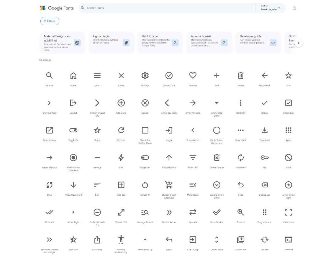
I got the symbols from Google Fonts. This symbols are open source free and without cost.
I used Power Point to make a "draft" of the app so I can make an idea of how I want the app to look like.
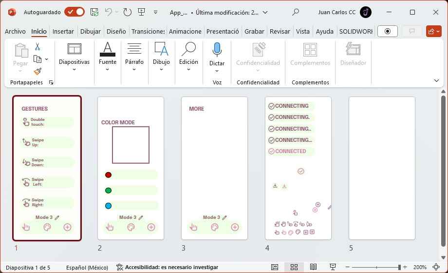
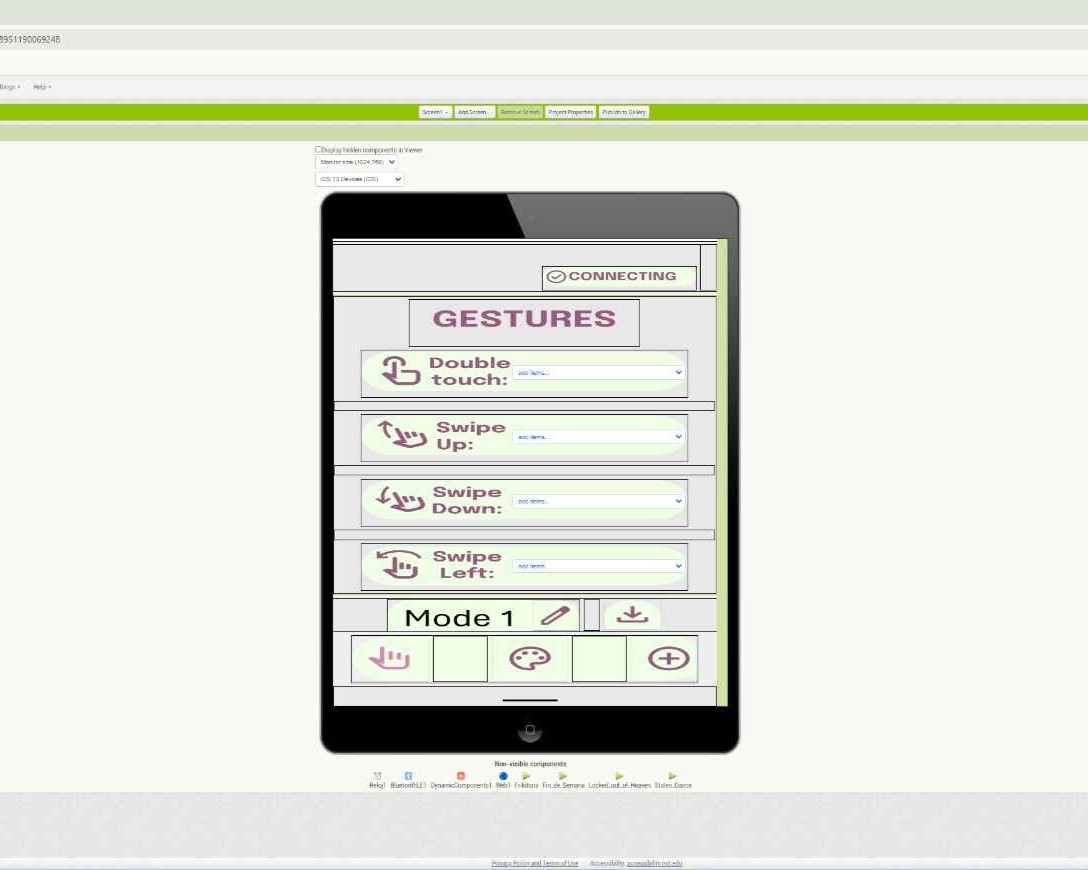
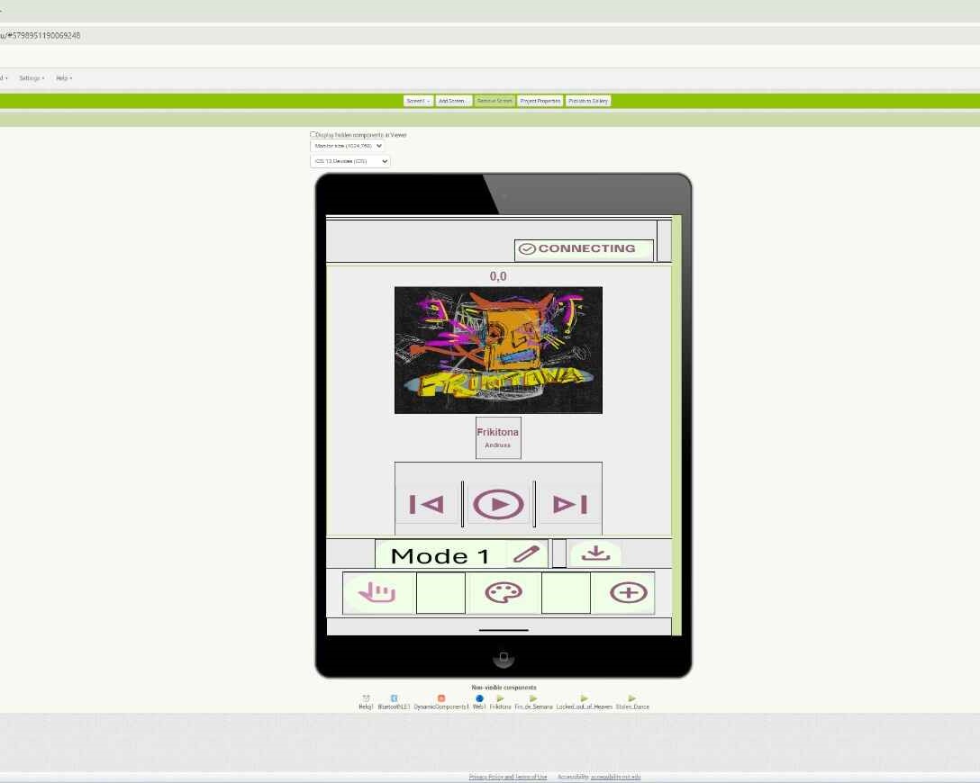
Here is the design part of the app on App Inventor.
Program
The coding of App Inventor is with blocks, her is an image of all the blocks that make the app work.
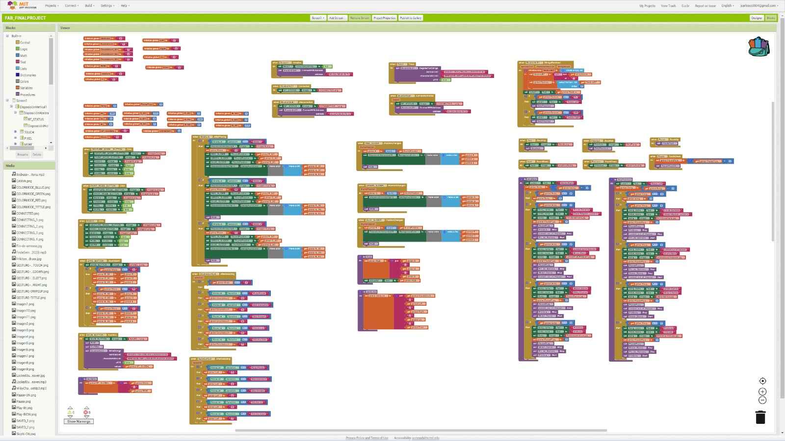
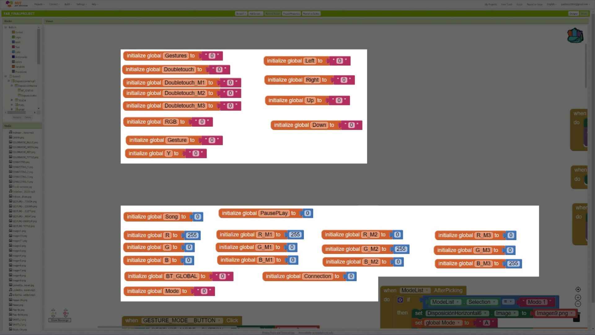
Initial Values
Here all all the values that the app starts with.
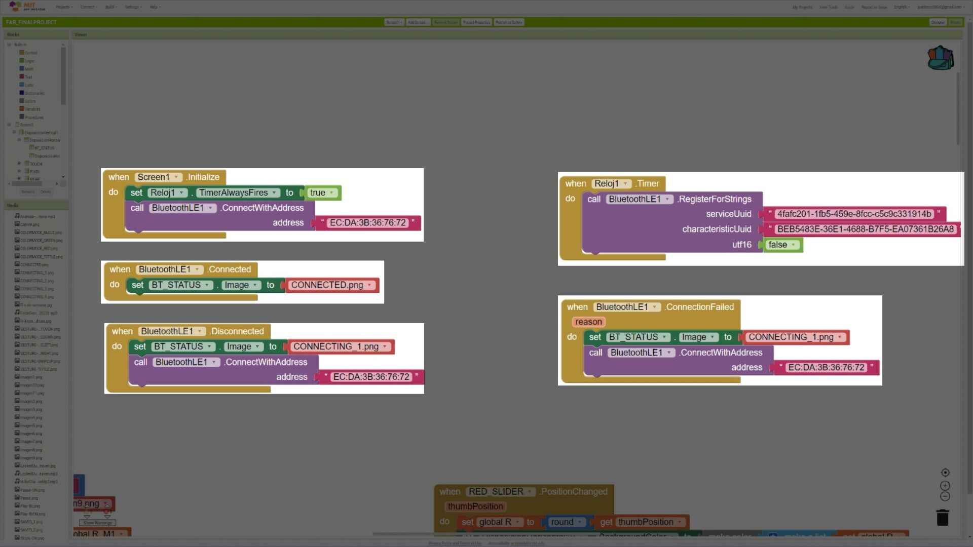
Bluetooth
This blocks make the bluetooth connection work. When the app opens it automatically looks for the device and if it is not found, it will look again until is connected.
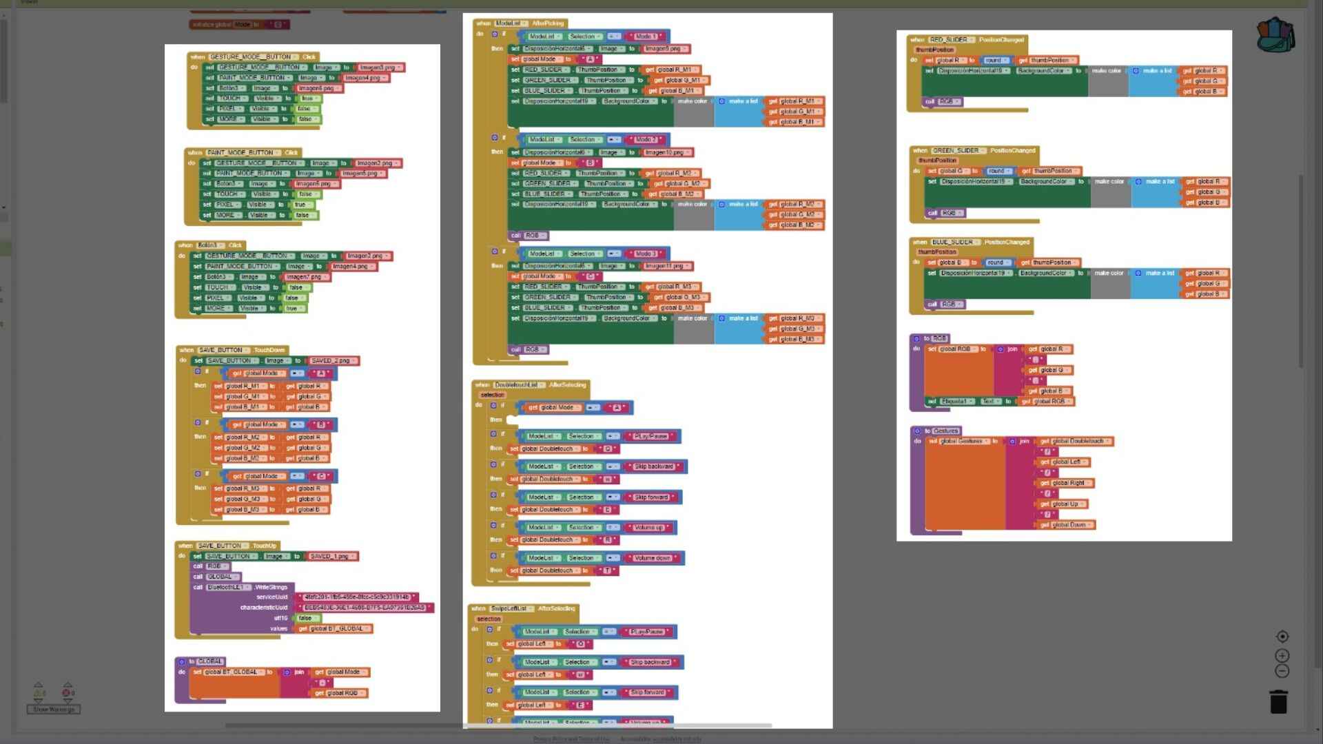
App customization
All this blocks make the app works, they are "in charge" of the customization. The blocks of the first column save the customization the user made and sends it to the divice.
The ones on the second and third column are the ones that modify and save the customization but only for the app.
Song tracks
Lastly this are the blocks that when they recieve the what gesterures the user is doing they make actions of that gesture.
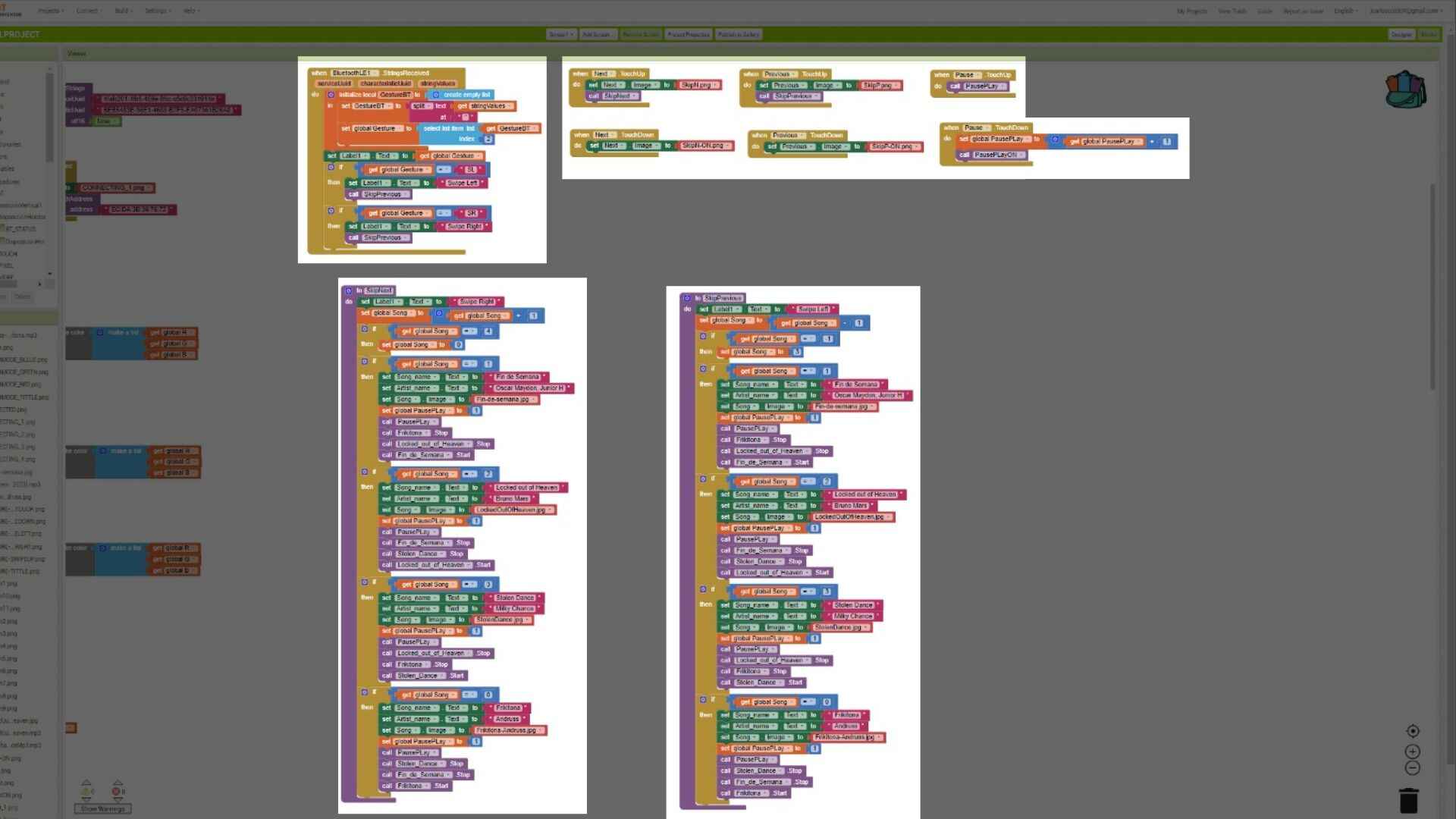
You can find the link of the app at the bottom the page on the File section. (It is a link beacuse, the size of the app its too big to upload in the page.)
Programming
The code is in C++ and I used Arduino to make it. I want to show you a few sections of the code that I consider are important before showing you de whole code.
Libraries
This are the libraries that I needed to make the code work.
//BLE libraries
#include < BLEDevice.h >
#include < BLEUtils.h >
#include < BLEServer.h >

#include < Adafruit_NeoPixel.h >	//Library of the NeoPixel
#include < Arduino.h >	//Arduino library
#include < Preferences.h >	//Library to save the data into the xiao
#include < Wire.h >	//Libraryto communicate with I2C
#include < Adafruit_MPR121.h >	Library of the MPR121 Module
Variables
The are the variables that the code will work with.
Preferences preferences; //Iniate an instance of the preference

// Create the sensor object
Adafruit_MPR121 cap = Adafruit_MPR121();
String Gesture; //String of the gestures
int currentXPosition = 0;  // Track the current value of x position
int currentYPosition = 0;  // Track the current value of y position
int previousXPosition = 0; // Track the previous value of x position
int previousYPosition = 0; // Track the previous value of y position

unsigned long lastTapTime = 0; // Time of the last tap

// Maximum delay between taps for double tap detection (milliseconds)
const unsigned long doubleTapDelay = 400;

//Button
int Mode = 0;	//Change modes of the device
int flag = 0;	//Avoid over pressing

//Neopixel
int PIN  = 2;
#define NUMPIXELS 1
Adafruit_NeoPixel pixels(NUMPIXELS, PIN, NEO_GRB + NEO_KHZ800);

//Bt DATA - The data that the device will recieve from the app
String redBT;
String greenBT;
String blueBT;
String modeBT;
int change = 1;
int modeS = 0;

//DATA
int Data[3][3] = {
	{255, 0, 0},  // Mode 1 {R, G, B}
	{0, 255, 0},  // Mode 2
	{0, 0, 255}   // Mode 3
};

//Rows and colummns to save the data
const int rows = 3;
const int cols = 3;

//Bluetooth
#define SERVICE_UUID        "4fafc201-1fb5-459e-8fcc-c5c9c331914b"
#define CHARACTERISTIC_UUID "beb5483e-36e1-4688-b7f5-ea07361b26a8"

BLECharacteristic *pCharacteristic; // Declare pCharacteristic as a global variable
Save and Load Data
I wanted the device to save the data if the user customize these are the functions that will make those tasks.
// Function that saves data
void saveData() {
	preferences.begin("matrix", false);
	for (int i = 0; i < rows; i++) {
		for (int j = 0; j < cols; j++) {
			String key = "cell" + String(i) + "_" + String(j);
			preferences.putInt(key.c_str(), Data[i][j]);
		}
	}
	preferences.end();
}

//Function that loads data
void loadData() {
	Serial.println("Loading Data...");
	preferences.begin("matrix", true);
		for (int i = 0; i < rows; i++) {
			for (int j = 0; j < cols; j++) {
				String key = "cell" + String(i) + "_" + String(j);
				// Default 0 if not exists
				Data[i][j] = preferences.getInt(key.c_str(), 0);
				Serial.println(Data[i][j]);
			}
		}
	preferences.end();
}
Recieve data via BLE
This is the part of the code that will recieve data and save it in each value.
//Recieve data via BLE
class MyCallbacks : public BLECharacteristicCallbacks {
	void onWrite(BLECharacteristic *pCharacteristic) {
		String value = pCharacteristic->getValue();
		redBT = "";
		greenBT = "";
		blueBT = "";
		if (value.length() > 0) {
			Serial.println("*********");
			Serial.print("New value: ");
			for (int i = 0; i < value.length(); i++) {
				// MODES
				if (value[i] == 'A') {
					modeS = 0;
				}
				if (value[i] == 'B') {
					modeS = 1;
				}
				if (value[i] == 'C') {
					modeS = 2;
				}

				// RGB
				if (value[i] == ',') {
					change = change + 1;
				}
				if (change == 1 && isdigit(value[i])) {
					redBT = redBT + value[i];
				}
				else if (change == 2 && isdigit(value[i])) {
					greenBT = greenBT + value[i];
				}
				else if (change == 3 && isdigit(value[i])) {
					blueBT = blueBT + value[i];
				}
			}

			Data[modeS][0] = redBT.toInt();
			Data[modeS][1] = greenBT.toInt();
			Data[modeS][2] = blueBT.toInt();

			Serial.print("Mode = ");
			Serial.println(modeS);
			Serial.println();
			Serial.println("LED COLOR");
			Serial.print("Red = ");
			Serial.println(Data[modeS][0]);
			Serial.print("Green = ");
			Serial.println(Data[modeS][1]);
			Serial.print("Blue = ");
			Serial.println(Data[modeS][2]);
			Serial.println();
			Serial.println("*********");
			change = 1;
			modeS = 0;

			saveData();
		}
	}
};
Final Code
	//BLE libraries
	#include < BLEDevice.h >
	#include < BLEUtils.h >
	#include < BLEServer.h >

	#include < Adafruit_NeoPixel.h >	//Library of the NeoPixel
	#include < Arduino.h >	//Arduino library
	#include < Preferences.h >	//Library to save the data into the xiao
	#include < Wire.h >	//Libraryto communicate with I2C
	#include < Adafruit_MPR121.h >	Library of the MPR121 Module

	Preferences preferences; //Iniate an instance of the preference

	// Create the sensor object
	Adafruit_MPR121 cap = Adafruit_MPR121();
	String Gesture; //String of the gestures
	int currentXPosition = 0;  // Track the current value of x position
	int currentYPosition = 0;  // Track the current value of y position
	int previousXPosition = 0; // Track the previous value of x position
	int previousYPosition = 0; // Track the previous value of y position

	unsigned long lastTapTime = 0; // Time of the last tap

	// Maximum delay between taps for double tap detection (milliseconds)
	const unsigned long doubleTapDelay = 400;

	//Button
	int Mode = 0;
	int flag = 0;

	//Neopixel
	int PIN  = 2;
	#define NUMPIXELS 1
	Adafruit_NeoPixel pixels(NUMPIXELS, PIN, NEO_GRB + NEO_KHZ800);

	//Bt DATA
	String redBT;
	String greenBT;
	String blueBT;
	String modeBT;
	int change = 1;
	int modeS = 0;

	//DATA
	int Data[3][3] = {
		{255, 0, 0},  // Mode 1 {R, G, B}
		{0, 255, 0},  // Mode 2
		{0, 0, 255}   // Mode 3
	};

	const int rows = 3;
	const int cols = 3;

	//Bluetooth
	#define SERVICE_UUID        "4fafc201-1fb5-459e-8fcc-c5c9c331914b"
	#define CHARACTERISTIC_UUID "beb5483e-36e1-4688-b7f5-ea07361b26a8"

	BLECharacteristic *pCharacteristic; // Declare pCharacteristic as a global variable

	// Function that saves data
	void saveData() {
		preferences.begin("matrix", false);
		for (int i = 0; i < rows; i++) {
			for (int j = 0; j < cols; j++) {
				String key = "cell" + String(i) + "_" + String(j);
				preferences.putInt(key.c_str(), Data[i][j]);
			}
		}
		preferences.end();
	}

	//Function that loads data
	void loadData() {
		Serial.println("Loading Data...");
		preferences.begin("matrix", true);
		for (int i = 0; i < rows; i++) {
			for (int j = 0; j < cols; j++) {
				String key = "cell" + String(i) + "_" + String(j);
				Data[i][j] = preferences.getInt(key.c_str(), 0); // Default 0 if not exists
				Serial.println(Data[i][j]);
			}
		}
		preferences.end();
	}

	//Recieve data via BLE
	class MyCallbacks : public BLECharacteristicCallbacks {
		void onWrite(BLECharacteristic *pCharacteristic) {
			String value = pCharacteristic->getValue();
			redBT = "";
			greenBT = "";
			blueBT = "";
			if (value.length() > 0) {
				Serial.println("*********");
				Serial.print("New value: ");
					for (int i = 0; i < value.length(); i++) {
						// MODES
						if (value[i] == 'A') {
							modeS = 0;
						}
						if (value[i] == 'B') {
							modeS = 1;
						}
						if (value[i] == 'C') {
							modeS = 2;
						}

						// RGB
						if (value[i] == ',') {
							change = change + 1;
						}
						if (change == 1 && isdigit(value[i])) {
							redBT = redBT + value[i];
						}
						else if (change == 2 && isdigit(value[i])) {
							greenBT = greenBT + value[i];
						}
						else if (change == 3 && isdigit(value[i])) {
							blueBT = blueBT + value[i];
						}
					}

					Data[modeS][0] = redBT.toInt();
					Data[modeS][1] = greenBT.toInt();
					Data[modeS][2] = blueBT.toInt();

					Serial.print("Mode = ");
					Serial.println(modeS);
					Serial.println();
					Serial.println("LED COLOR");
					Serial.print("Red = ");
					Serial.println(Data[modeS][0]);
					Serial.print("Green = ");
					Serial.println(Data[modeS][1]);
					Serial.print("Blue = ");
					Serial.println(Data[modeS][2]);
					Serial.println();
					Serial.println("*********");
					change = 1;
					modeS = 0;

					saveData();
			}
		}
	};

	void setup() {
		// Serial
		Serial.begin(115200);

		Serial.println("Setting up");
		preferences.begin("my-app", false);

		loadData();

		// Bt
		BLEDevice::init("AMEC");
		BLEServer *pServer = BLEDevice::createServer();

		BLEService *pService = pServer->createService(SERVICE_UUID);

		pCharacteristic = pService->createCharacteristic
		(CHARACTERISTIC_UUID, BLECharacteristic::PROPERTY_READ
		| BLECharacteristic::PROPERTY_WRITE | BLECharacteristic::PROPERTY_NOTIFY);

		pCharacteristic->setCallbacks(new MyCallbacks());

		pCharacteristic->setValue("Hello World");
		pService->start();

		BLEAdvertising *pAdvertising = pServer->getAdvertising();
		pAdvertising->start();

		// Initialize Pixel
		pixels.begin();
		pixels.clear();
		pixels.show();

		// Button
		pinMode(D6, INPUT);

		// Initialize the sensor
		if (!cap.begin(0x5A)) {  // Default I2C address for MPR121 is 0x5A
			while (1);
		}
	}

	void loop() {
		// Get the currently touched pads
		int touched = cap.touched();

		// Reset current positions
		currentXPosition = 0;
		currentYPosition = 0;

		// Check each pad to see if it is currently touched
		for (int i = 0; i < 12; i++) {
			if (touched & (1 << i)) {
				if (i < 6) {  // Pins 0-5
					currentXPosition = i + 1;  // Save the position (1-based)
				}
				else {  // Pins 6-11
					currentYPosition = (i - 6) + 1;  // Save the position (1-based)
				}
			}
		}

		if (digitalRead(D6) == HIGH) {
			if (Mode < 2 && flag == 0) {
				flag = 1;
				Mode = Mode + 1;
				Serial.println("Button pressed");
			}
			if (Mode == 2 && flag == 0) {
				Mode = -1;
			}
		}
		else if (digitalRead(D6) == LOW) {
			flag = 0;
		}

		if (Mode == 0) {
			pixels.clear();
			pixels.setPixelColor(0, pixels.Color(Data[0][0], Data[0][1], Data[0][2]));
			pixels.show();
		}
		else if (Mode == 1) {
			pixels.clear();
			pixels.setPixelColor(0, pixels.Color(Data[1][0], Data[1][1], Data[1][2]));
			pixels.show();
		}
		else if (Mode == 2) {
			pixels.clear();
			pixels.setPixelColor(0, pixels.Color(Data[2][0], Data[2][1], Data[2][2]));
			pixels.show();
		}

		// Detect gestures
		if (currentXPosition != 0 || currentYPosition != 0) {
			// Detect double tap
			unsigned long currentTime = millis();

			// Detect swipe gestures
			if (previousXPosition != 0 && previousYPosition != 0) {
				if (currentXPosition == previousXPosition) {
					if (currentYPosition < previousYPosition) {
						Serial.println("Swipe Up Detected");
						Gesture="SU";
						// Convert std::string to C-style string
						pCharacteristic->setValue(Gesture.c_str());
						pCharacteristic->notify();
						delay(2000);
					}
					else if (currentYPosition > previousYPosition) {
						Serial.println("Swipe Down Detected");
						Gesture="SD";
						// Convert std::string to C-style string
						pCharacteristic->setValue(Gesture.c_str());
						pCharacteristic->notify();
						delay(2000);
					}
				}
				else if (currentYPosition == previousYPosition) {
					if (currentXPosition < previousXPosition) {
						Serial.println("Swipe Left Detected");
						Gesture="SL";
						// Convert std::string to C-style string
						pCharacteristic->setValue(Gesture.c_str());
						pCharacteristic->notify();
						delay(2000);
					}
					else if (currentXPosition > previousXPosition) {
						Serial.println("Swipe Right Detected");
						Gesture="SR";
						// Convert std::string to C-style string
						pCharacteristic->setValue(Gesture.c_str());
						pCharacteristic->notify();
						delay(2000);
					}
				}
			}

			// Update previous positions
			previousXPosition = currentXPosition;
			previousYPosition = currentYPosition;
		}

		else {
			// Reset previous positions if no touch detected
			previousXPosition = 0;
			previousYPosition = 0;
		}

		delay(100);
	}
You can find the file of the Arduino code at the bottom the page on the File section.
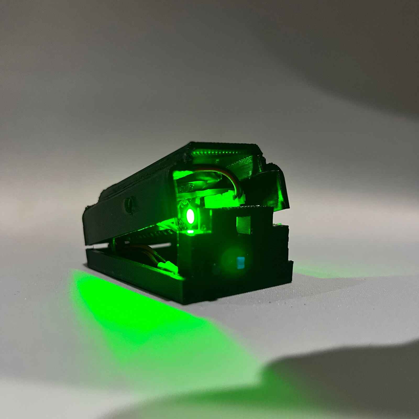
Final Result
Here are some photos and videos of the Final Result.
Files
A.M.E.C. (Auditive Modern Electronic Clothing) by Juan Carlos Chávez Cortés is licensed under Creative Commons Attribution-NonCommercial 4.0 International![]()
![]()
![]()