2. Computer-aided Design
On this week I worked on learning to use programs of 2D and 3D design, looking for advantages for a lot of different programs.
3D Programs
This is a list of three 3D designing programs that are commonly used in the industry:
- Autocad: It is a versatile 3D modeling software used in architecture, engineering and construction industries. It allows the creation of precise 2D and 3D models for different systems. It offers an easy set of tools for drafting, modeling and rendering. It supports parametric modeling and has a lot of compatibility with other Autodesk products.

- Blender: It is a free, open-source 3D modeling software used for animation, game development, visual effects and 3D printing. It provides a comprehensive set of modeling, sculpting, texturing, animation and rendering tools. It supports a variety of file formats and has a big community that contributes to its improvement.

- SolidWorks: It is a parametric 3D modeling software designed for mechanical design and engeineering applications. It is used in aerospace, automotive and manufacturing industries. This software enables the creation of easily editable and adaptable designs. It offers advanced simulation and analysis tools, making it great for testing the structural and dynamic properties.

- Catia: It is a comprehensive 3D modeling software used in industries such as aerospace, automotive, and industrial design for creating complex surface and solid models. It offers advanced surface modeling capabilities, making it ideal for designing highly complex shapes and surfaces

3D modeling
The 3D program I am going to use is SolidWorks, because it is similar to Fusion360 and has most of the Catia tools (program I learned to use at University).
The piece I designed its a plunger. To design this piece, I used an existant drawing that I already had. To download the PDF file of the drawing click here. I have to specify that this wasn't my first time using SolidWorks and other similar softwares. The basic process of designing in SolidWorks is making a figure on a sketch on a plane and starting to extruding sketch by sketch.
To show an example of how SolidWorks its used, I am going to explain how I design the plunger:
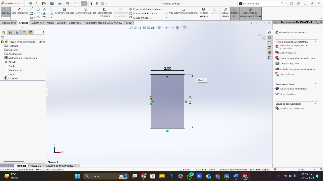
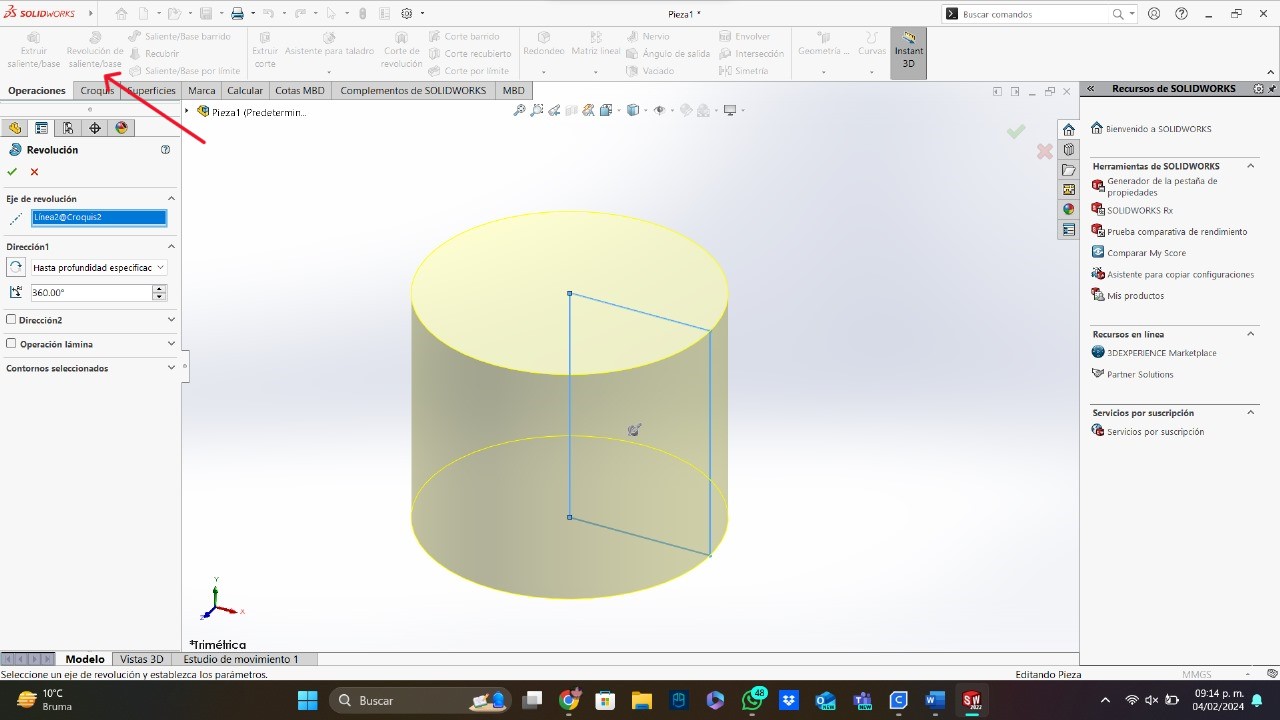
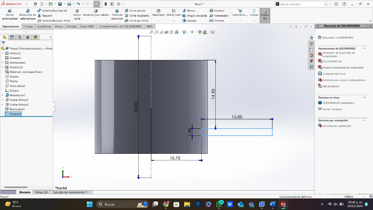
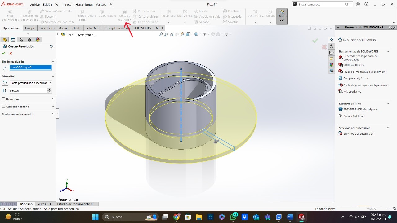
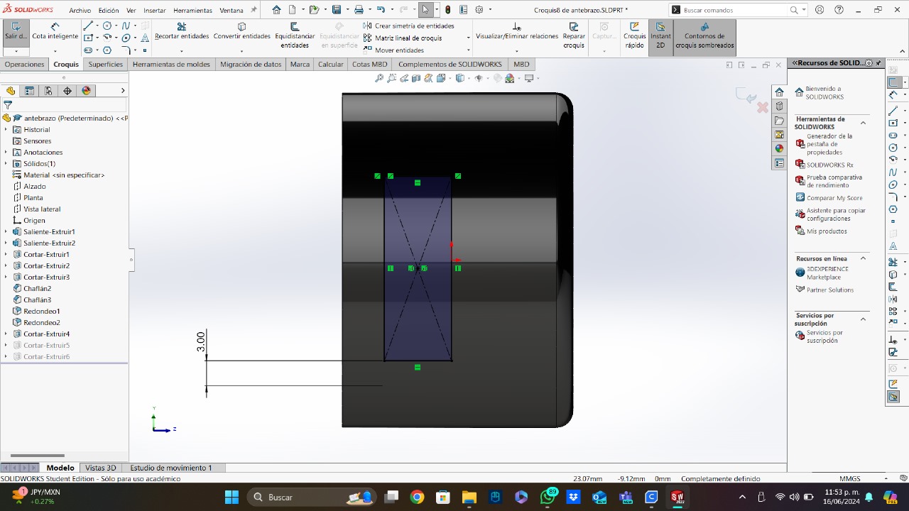
- Basic Figure: I selected one of the planes and I created a rectangle with one of the sides aligned with the vertical axis. I drew the rectangle in this way to use this side as a revolution axis (the tool used is pointed with a red arrow).
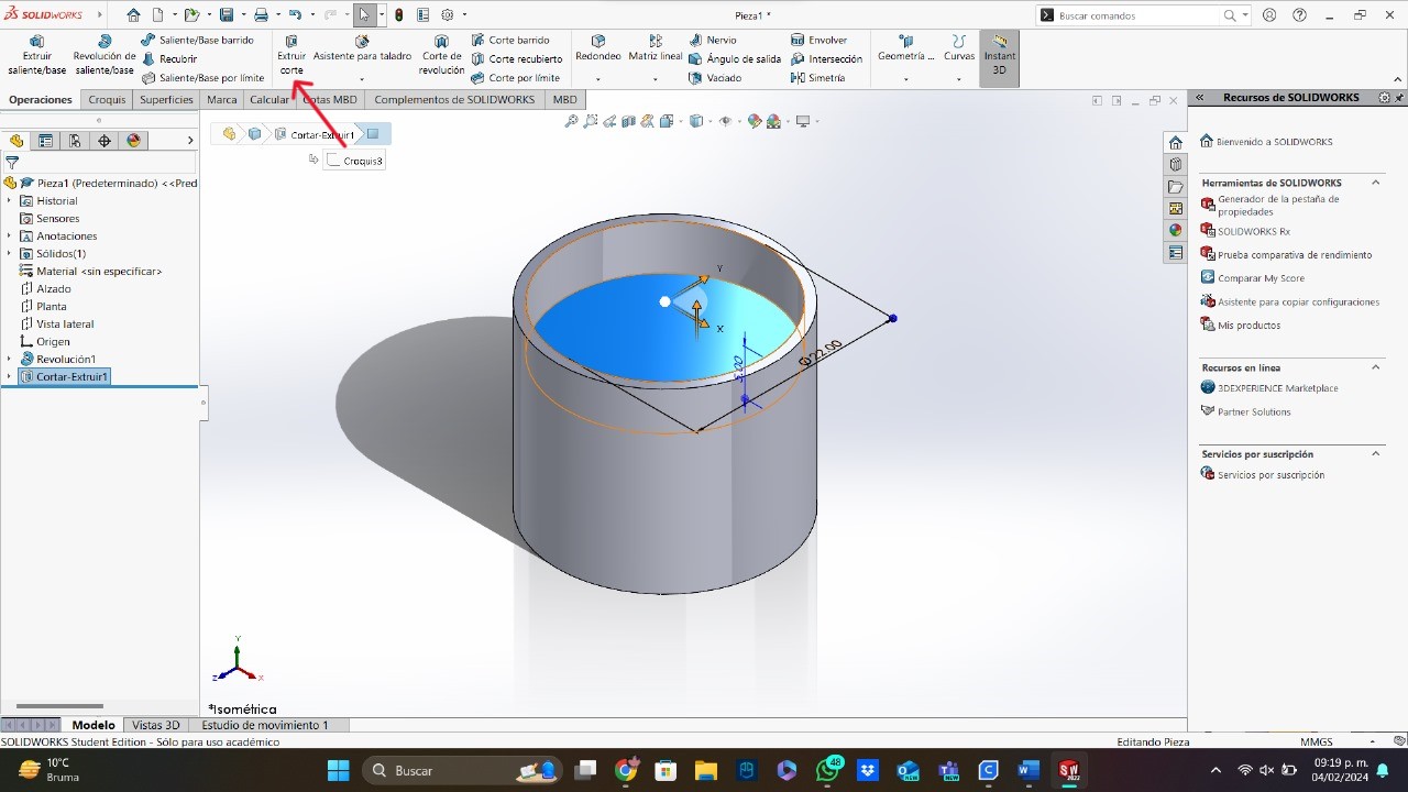
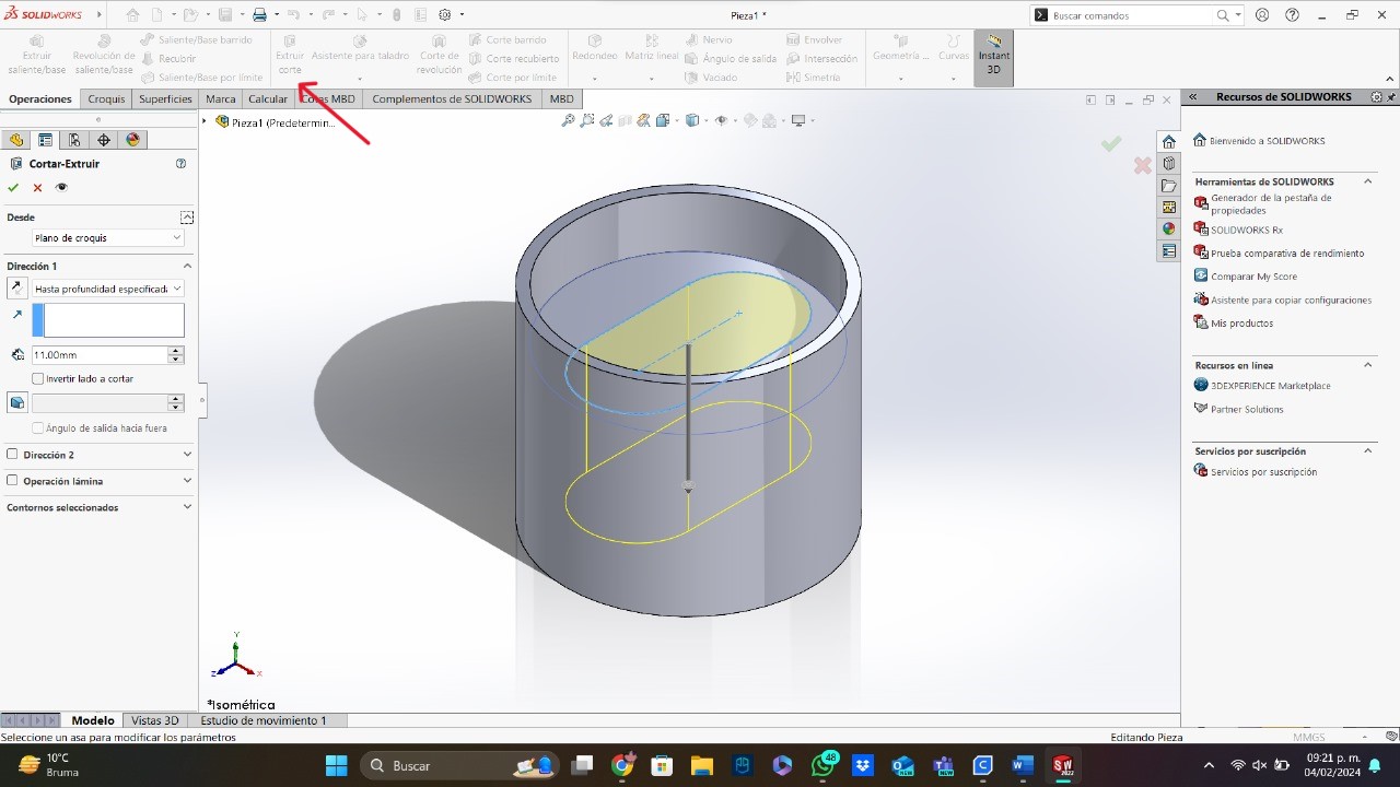
- Pockets: To make the first two pockets, I used the same logic in both of them. The things that were different were the figures to pocket, the planes used and the lenght of each pocket.
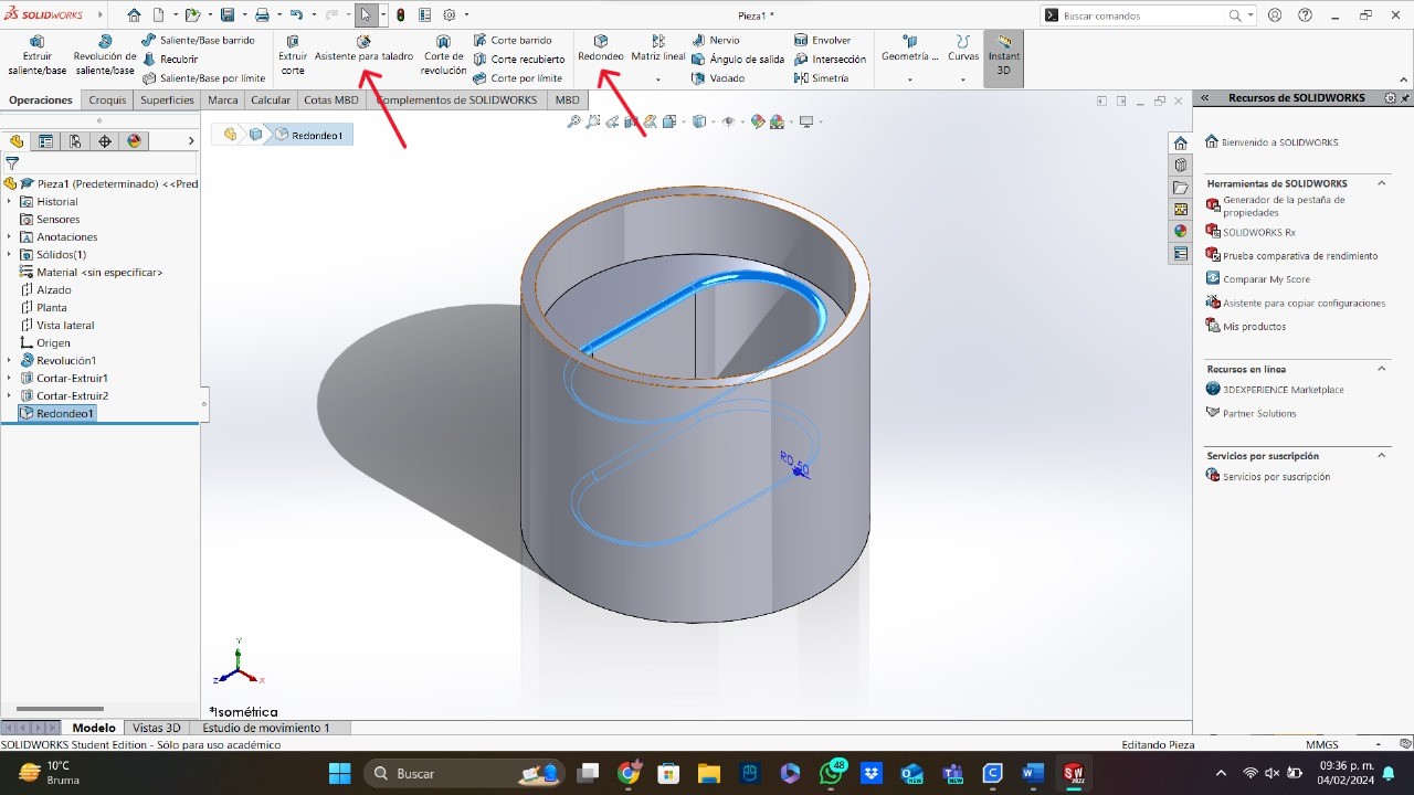
- Grooves: The groove is very similar to the shaft operator, because it needs a sketch and a revolution axis, but to delete material instead of create. To design the grooves, I used 2 different sketches, you can do it just in one.
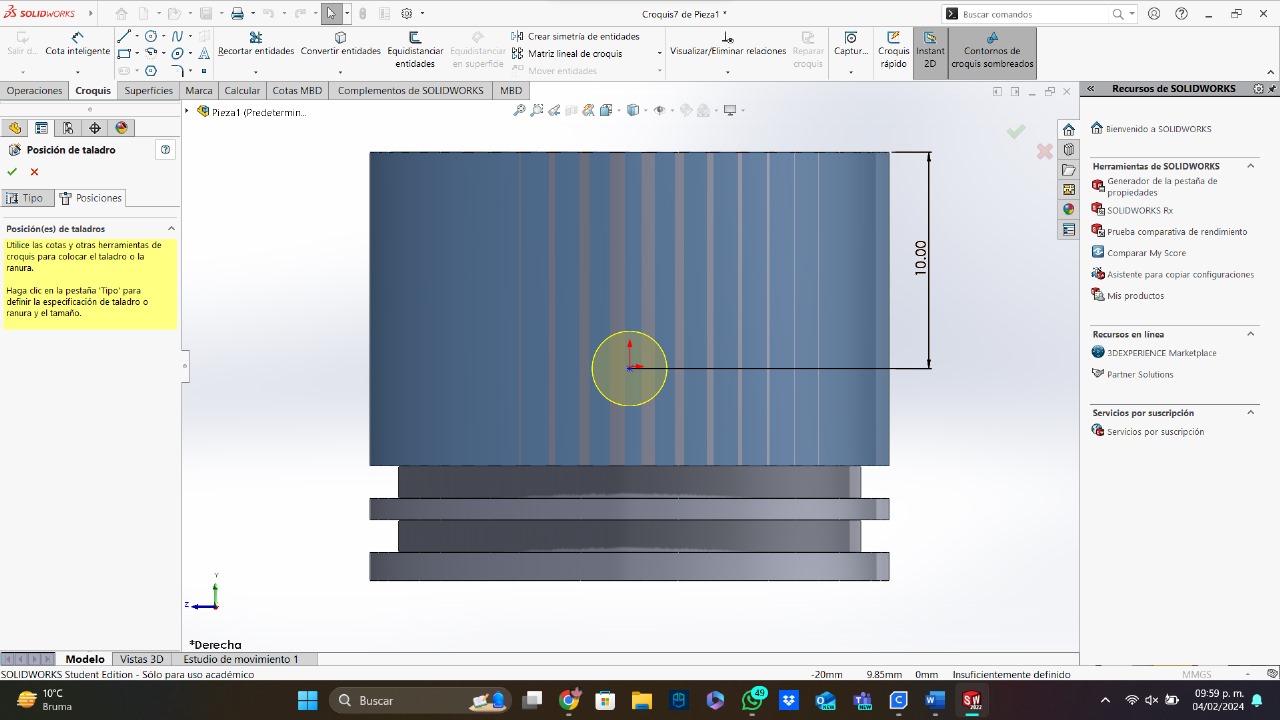
- Holes, Chamfer and Edge Fillet: To create a hole, I used the drill tool on the surface needed and change the hole limit. The chamfer and edge fillet tools have similar functions and have the same way to use. To use the chamfer and edge fillet tools, you just have to select the edges of your 3D model and the lenght of each tool.
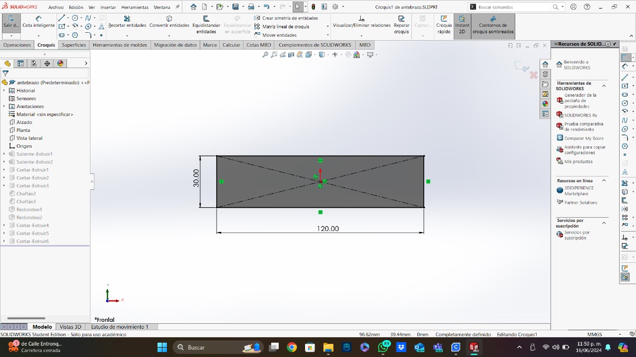
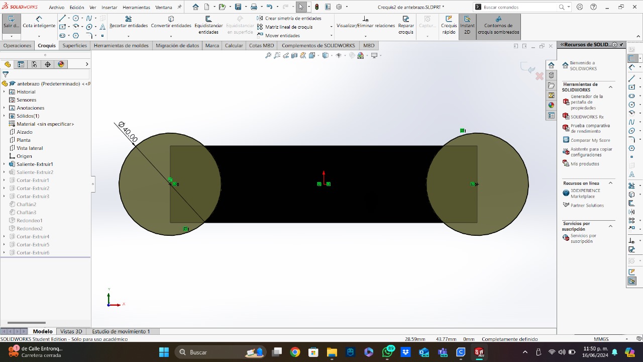
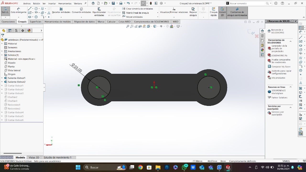
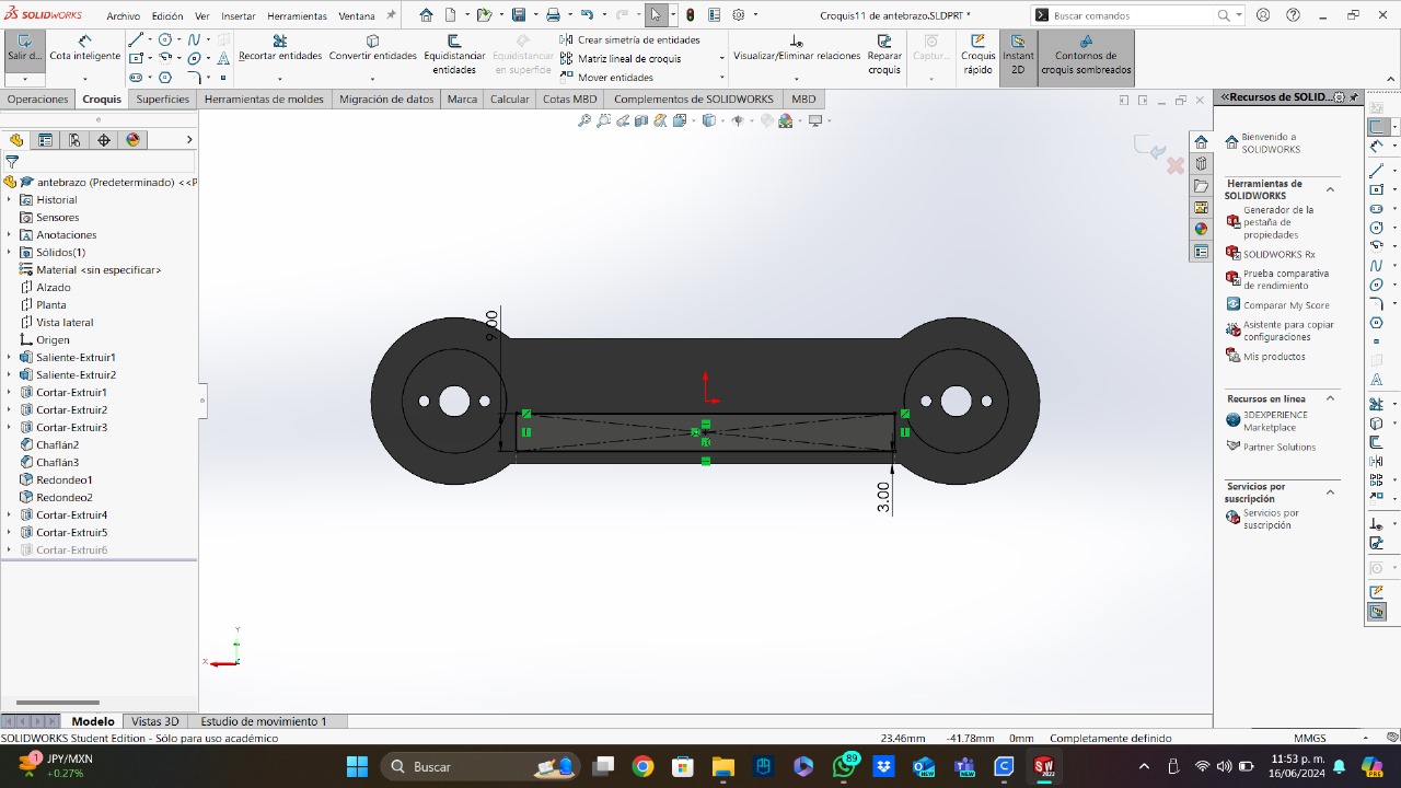
- Basic Figure: For the basic figure, I made a rectangle with 2 circles at the end of each side.
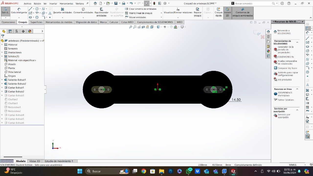
- Couplings: To join this piece with the servomotors, I had to add different holes to be able to join the couplings. In addition, I also added a hole at the top to facilitate assembly and to adapt to the length of the pins that come with the servos.
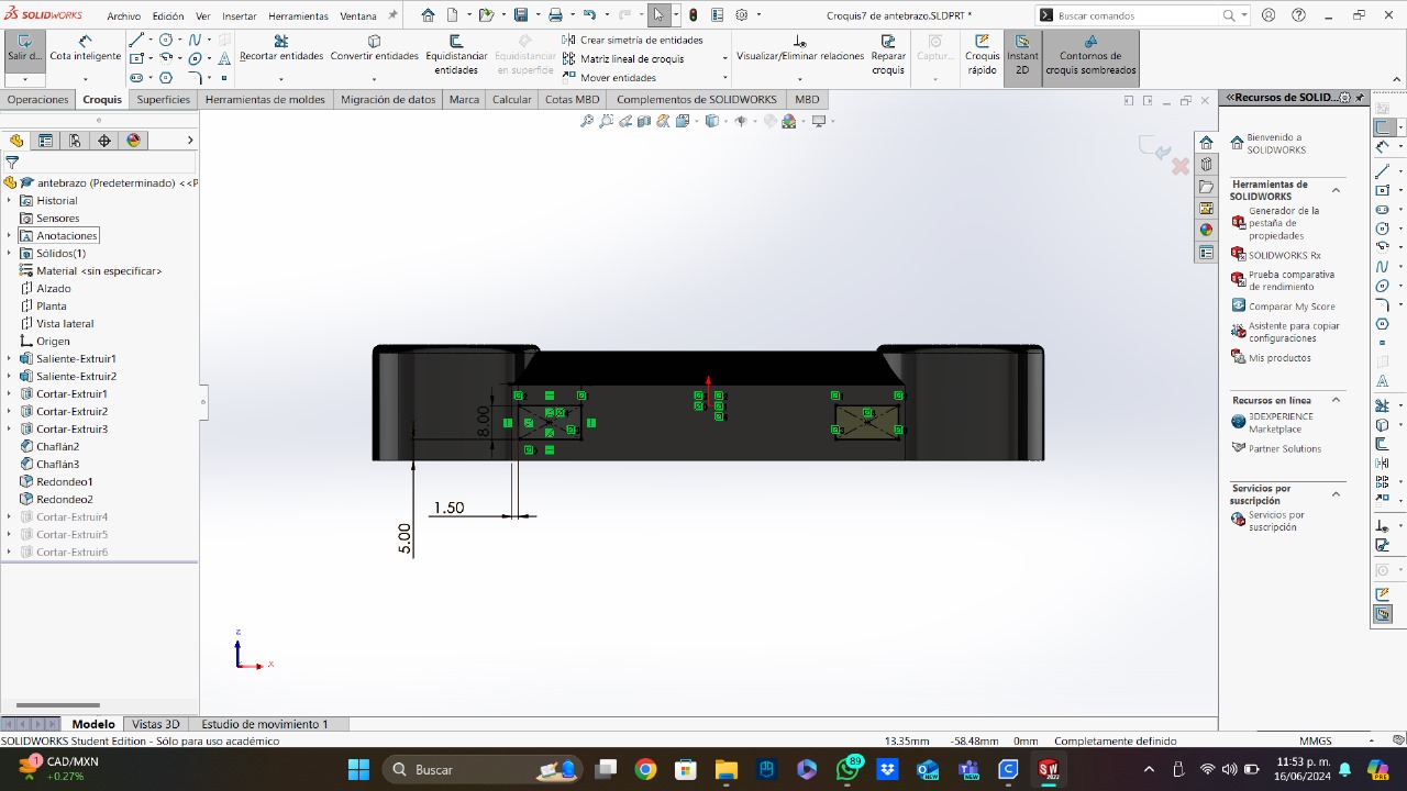
- Chamfers And Fillets: I added some chamfers and fillets to the piece in order to make it look better and more aesthetic.
- Wire Slots: Finally, and in order to improve the wire management, I added some slots to the bottom in order to hide most of the wires.
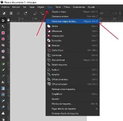
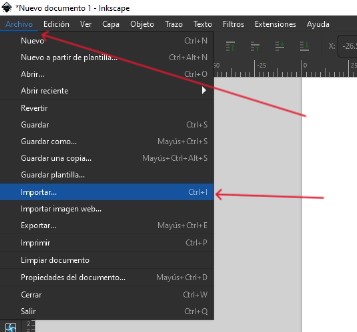
- Preparing the image: After opening Inkscape using the default options, I opened the vectorize panel on the streak tools. Then, on the file tools, I selected "import" and chose my image.
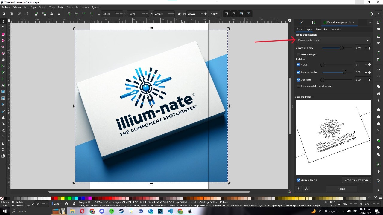
- Vectorize: To vectorize my logo, I selected the "Edge detection" mode and apply it to my image.
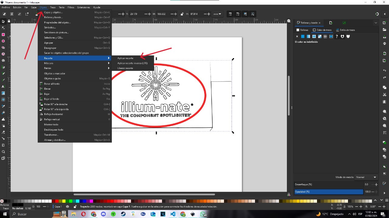
- Trim: To delete the parts that are not from the logo, I used a circle and the trim options on the object tools.
That was a quick summarize of random process of designing a part. You can also add material to your part and simulate different kind of things. To download this part, you can click here.
Why SolidWorks?
SolidWorks is preferred in some industries, particularly mechanical design and engineering, due to its parametric modeling capabilities. It stands out in creating precise 3D models of mechanical components and assemblies. SolidWorks also offers advanced simulation and analysis tools.
Its user-friendly interface and seamless integration with other engineering softwares makes it a preferred choice for efficient product development processes. SolidWorks is easy to learn compared with softwares like Catia, it is also cheaper than this one and has a bigger community that can help with ideas, models or tutorials. In my experience, I can say that SolidWorks is faster than Catia and the way Solidworks's interface is made, helps me to find quicker all the tools I need. This is an screenshot of the same piece designed in SolidWorks and Catia:
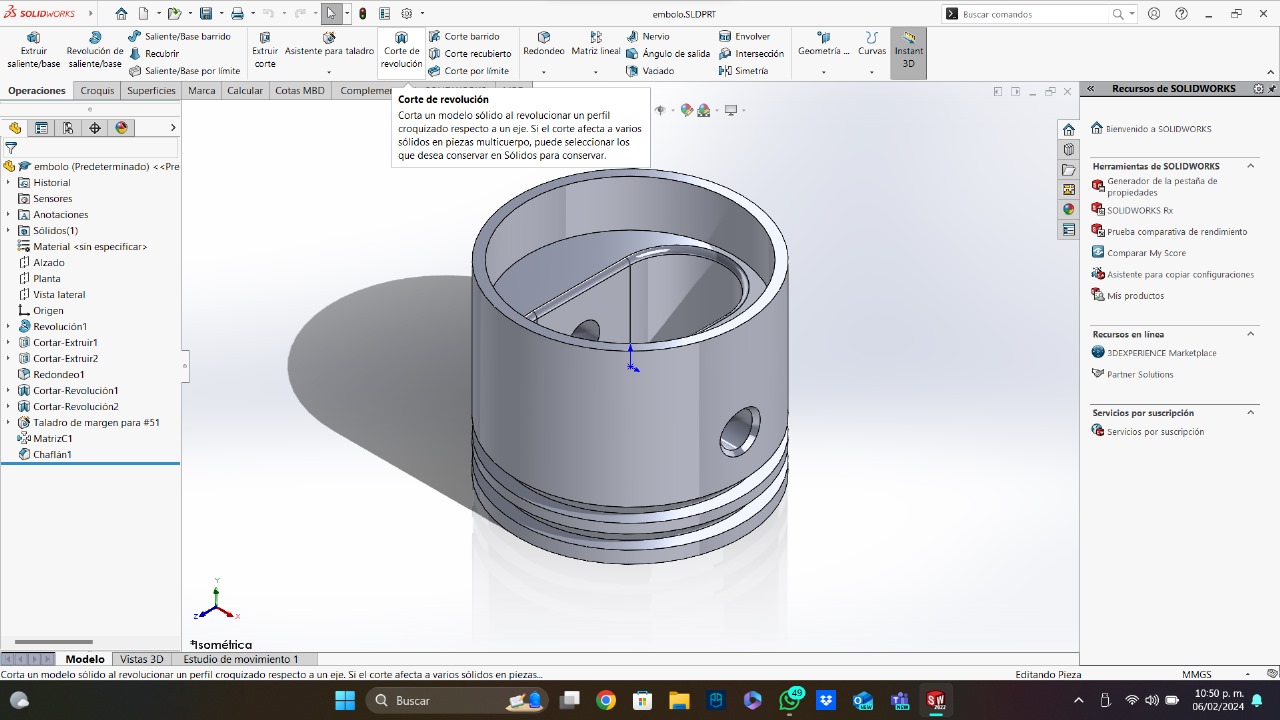
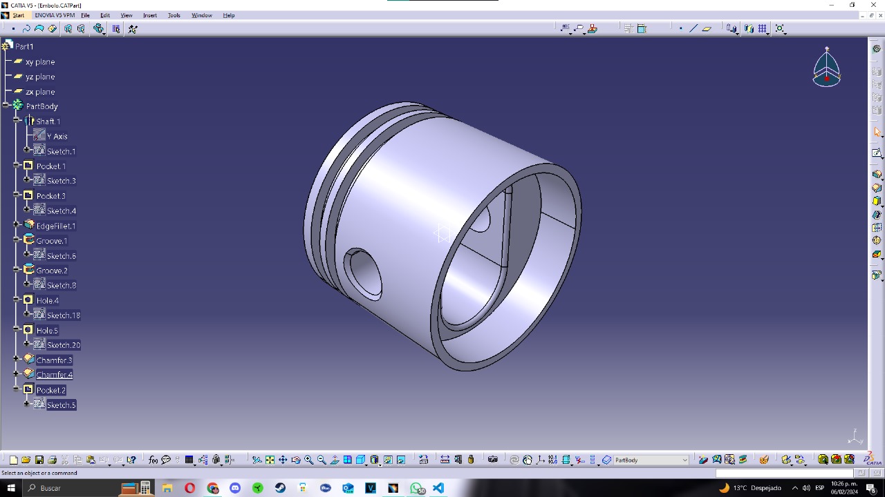
Like we can see above, the way SolidWorks and its tools are presented, is better and friendlier than the way Catia does. In SolidWorks, each tool has a little description of its function, this is a very useful thing that would be great in every 3D designing softwares. I also took the time of how much I lasted designing and I found out that I lasted less designing in SolidWorks than in Catia. These three things prove that SolidWorks is easier to learn and use than Catia and other 3D designing softwares (but both are great options to use).
Final Project Piece
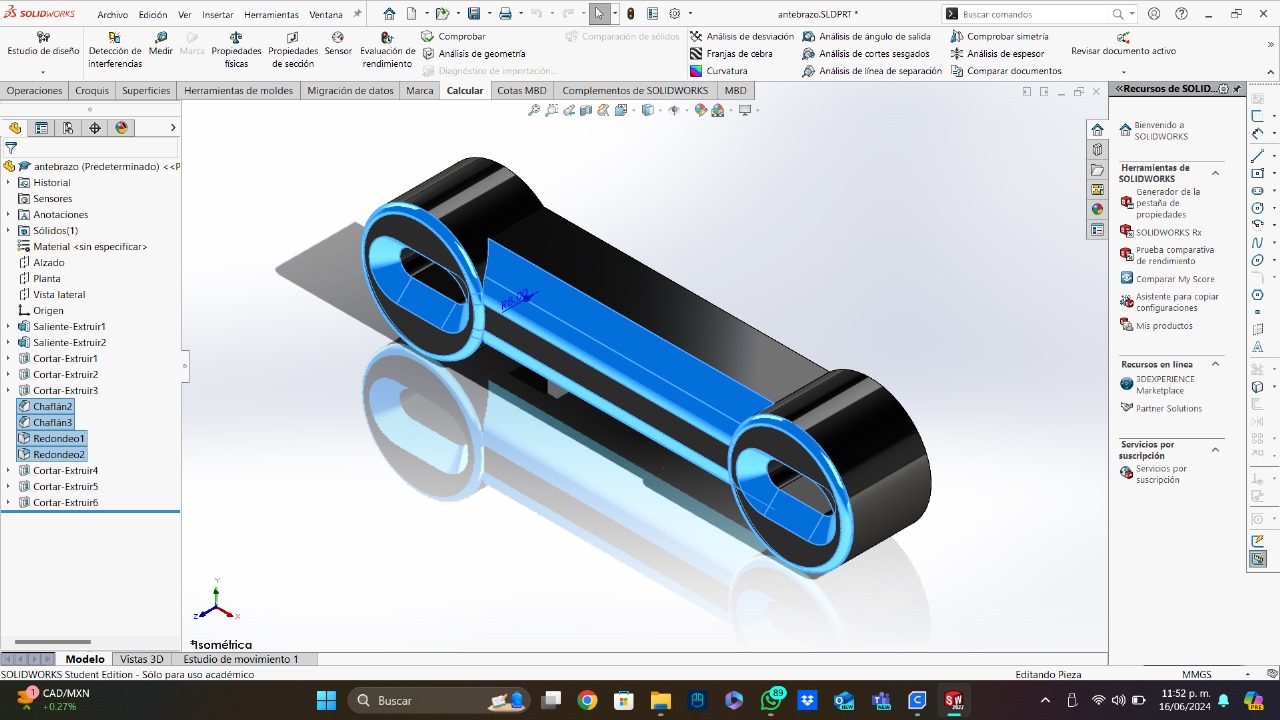
For this week, I designed the middle part of my final project robotic arm. This part is made for being attached to 2 servomotor (one at each end of the piece). The servomotors I will use are the MG990, so I needed to design the piece thinking about the couplings for this model.
Now, I am going to explain how I created this piece:

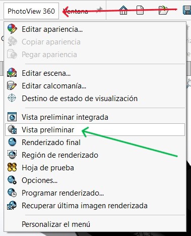
Rendering
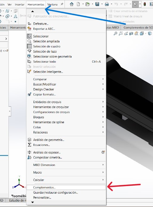
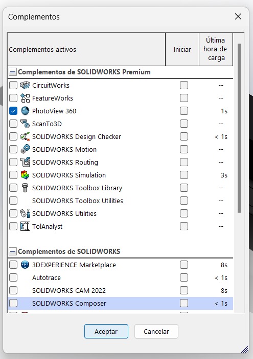
The rendering part is very easy, first, you should go to "Tools", then to "Complements" and then you should add "PhotoView 360".
Then, you should go to the photoview section, and add a "Preliminar View", you should add a cam or use the actual view and you have a render.
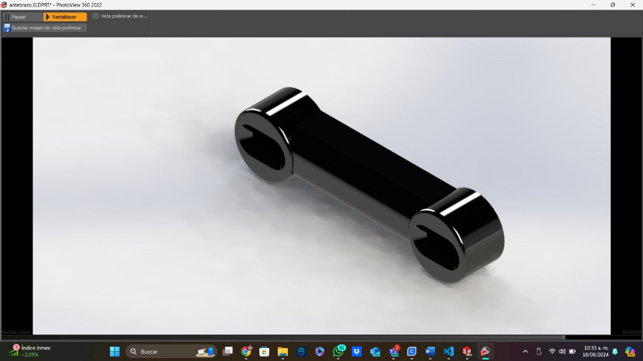
Here is a render of the part explained above:
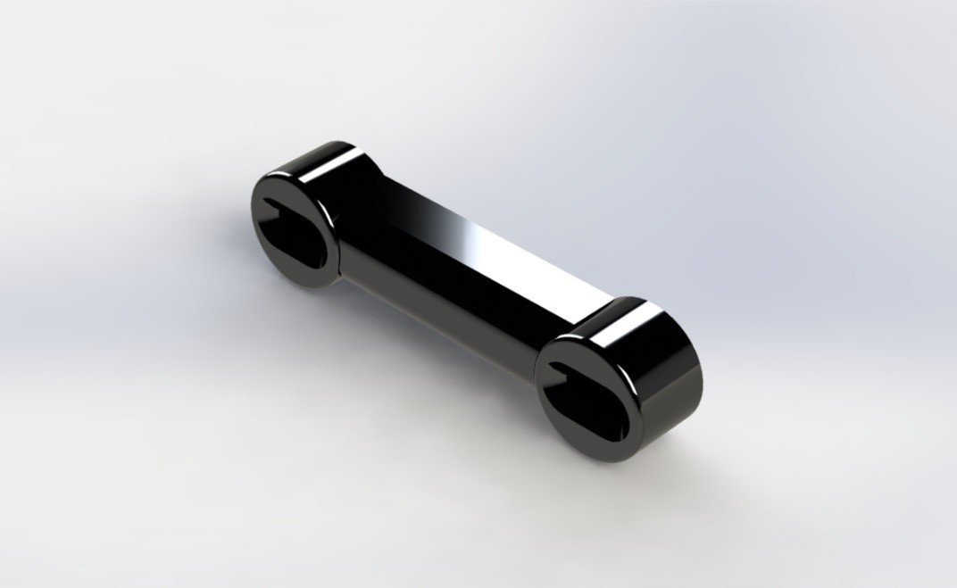
To download this part, you can click here.
2D Design
In this case, I will use one artificial intelligence (ChatGPT 4) to generate ideas for my final project logo. Then, I will use the software Inkscape to create the final version of my final project logo. I will use Inkscape because it is a free software that I have already used in the past, and because it can vectorize images automatically.
I wrote to ChatGPT the next quote: "Generate me a logo for a little machine called "Illumi-Nate: The component spotlighter", the machine is a little laser controlled with 2 motors that points to the components you want to take, it works selecting the component on a little OLED display". I told the AI that I wanted a serious, extremely clean and simple, and blue and white logo. ChatGPT generated me the next image:
This was a great logo, but that wasn't what I was looking for, so I asked the AI to make the center simpler, and this is what I got:
I was glad with this new logo, so the next part was to vectorize it on Inkscape. This process is very fast and you don't need a lot of experience to do it. This is hoy I do it:
And that's how you get a clean logo using the Inkscape options. With this version of the logo, you can edit and modify it, scale it without lossing quality, use it to print it, and many other functions. To download the SVG file of my logo, click here.