10. Mechanical Design
This week's assignment was the biggest project we had up till now in the Fab Academy for this reason we were assigned a team to work together in the design and building of our CNC the design and machine. All the documentation for the design and build of the CNC alongside the original files for our 3D designs and codes can be found on our group page. Machine6 group page
My contribution to the project
During the CNC processes, we did most things together, but there were also times when we divided the tasks depending on the skills and areas of study of each of the team members.
I would say my contribution to the project was more focused on the mechanical and electrical materials of the CNC, first of all, we had the opportunity to work with two engineering professors from Ibero Mexico City, Mario Ramirez and Daniel Perez. I reunited with them and they told me that they could lend us some aluminum profiles to make the CNC, so we agreed on a date, and with our final design finished in 3D modeling I went to Mexico City to get the mechanical materials needed for the CNC.
Our CNC 3D model
Trip to Mexico City
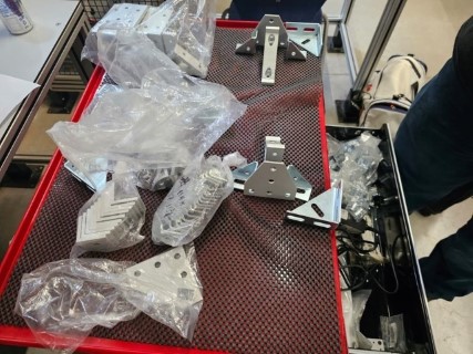
Getting to know Mexico City's Ibero was a fun experience, there I reunited with the professors. First, they gave me all the screws and unions for the aluminum profiles.
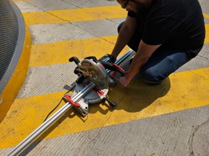
After that, we went for the aluminum profiles, they had a two big pieces of 6m, and since I needed them to fit in a car we decided to cut them, with a saw into pices of 1.30m.
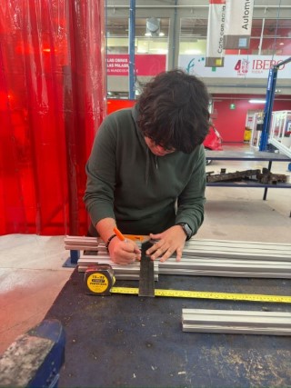
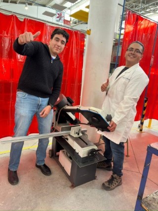
Once we acquired the materials, it was time to return to Puebla. Upon arrival, we commenced the assembly of the CNC machine, meticulously following the intricacies of the 3D design blueprint. With the design blueprint and all required materials at hand, replicating the structure was a straightforward task. The next step involved adjusting the length of the aluminum profiles and metal rods. Some of them were longer than necessary, prompting a visit to the metal cutting band saw machine to trim them to the correct dimensions.
Electronics and stepper motors
Another big part of my participation of my participation on the CNC was the electronic assembly and the stepper motor test. Another big part of my participation of my participation on the CNC was the electronic assembly and the stepper motor test. For the electronic materials, we used an Arduino CNC Shield, Pololu A4988 drivers, Nema 17 stepper motors, dupont cables, and stepper motor cables.
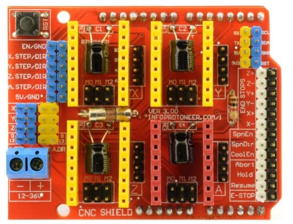
The Arduino CNC Shield is a compact board designed to facilitate the control of up to 4 stepper motors using your Arduino, owing to its shield format. It is compatible with both Pololu A4988 and Pololu DRV8825 power drivers (not included), offering versatile motor control capabilities. Additionally, it features all essential connections for integrating end stop switches, relay outputs, and various sensors. Fully compatible with the GRBL control firmware, this shield can be seamlessly utilized with any Arduino model, although the Arduino UNO is recommended for optimal performance. To utilize the Arduino CNC Shield, we connected it to an Arduino UNO. The Arduino UNO is recommended for this purpose because its pins perfectly align with those of the Shield, ensuring seamless compatibility and optimal functionality.
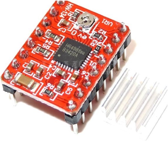
To operate the stepper motors effectively, we required drivers for each motor. Each driver needed to be calibrated to a specific current limit based on the model of the motor being used. To calibrate the drivers, we first determined the reference voltage by dividing the required current of the motors (in this case, 1.2A for the Nema 17) by 2.5 ohms. This calculation yielded the reference voltage. Subsequently, we calibrated the drivers using a multimeter and adjusted a potentiometer knob accordingly.
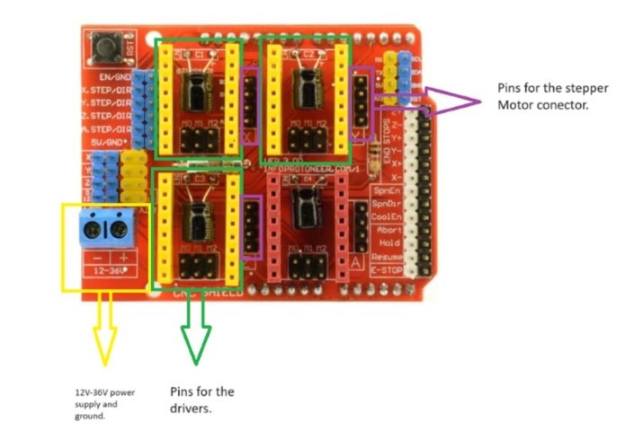
Once the driver calibration is completed, we proceed to the connections on the shield. Initially, we supply power to the CNC Shield, which typically ranges from 12V to 36V. The specific voltage required depends on factors such as the number of drivers and the type of motors being controlled, which can affect the current needed. Subsequently, we utilize the pins designated for the drivers and the pins responsible for connecting to the stepper motor connections.
For the Arduino to work properly we need to install GRBL which will allow the Arduino to interpret G-Code. You can see how to install it in the group page.
Finally I made a quick code in Arduino to check that the stepper motors were working
My experience
Conclusion This assignment has been my favorite so far, I'm in the fourth semester of my career, and having the opportunity to work with people who are way more experienced and advanced than me allowed me to learn a lot during the two weeks we spent on this assignment. Facing different challenges and being forced to look for solutions to unexpected problems during the process of making the CNC really helped me to improve a lot.