Welcome to FabLab Puebla: Paintball CNC Team,
In the innovative realm of digital fabrication, FabLab Puebla pioneers by merging the vibrant art of paintball with the precision of CNC technology. Our project, the Paintball CNC Machine, stands as a testament to creativity and engineering, transforming the way custom artwork is created. This unique venture was born from the idea of utilizing paintballs to generate intricate, large-scale drawings, demonstrating that the intersection of play and precision can lead to remarkable outcomes.
This documentation unfolds the journey of creating the Paintball CNC Machine, a project realized with a collective spirit and a shared vision for pushing the boundaries of conventional art creation. The initiative was spearheaded by a dynamic team from FabLab Puebla, consisting of dedicated individuals who share a passion for innovation:

Our venture into building the Paintball CNC Machine was driven by the desire to incorporate an element of unpredictability and excitement into digital fabrication. Unlike traditional CNC machines that cut or engrave with unwavering precision, our machine uses paintballs as its medium, offering a blend of accuracy and the delightful randomness of splattered paint. This project not only challenges the norms of digital art but also introduces a new way to think about and interact with CNC technology.
Throughout this documentation, we will guide you through the various stages of building the Paintball CNC Machine, from conceptualization to the final execution. Each phase of the project reflects our commitment to innovation, teamwork, and the joy of creating something truly unique. This collaborative effort showcases the strength and creativity of our team at FabLab Puebla and serves as an inspiration for future projects that lie at the intersection of art and technology.
Join us on this extraordinary journey as we delve into the creation of the Paintball CNC Machine, a project that symbolizes the fusion of art, technology, and community at FabLab Puebla.
Mechanical Design (part 1 of 2):
Machine Design (part 2 of 2)
Paintball guns, also known as paintball markers, operate on a fascinating principle that combines mechanical engineering with the physics of compressed gas to propel paintballs through the barrel and towards a target. The basic mechanics can be summarized in a few steps:
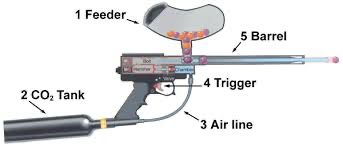
When the trigger is pulled, a series of mechanical and gas-driven events occur in rapid succession: the CO2 tank releases a measured burst of gas through the air line, which propels the paintball from the firing chamber, through the barrel, and towards the target. The feeder continually supplies new paintballs to be fired, maintaining a consistent rate of shooting as long as the trigger is actuated and there are paintballs available.
However there was a specific situation at IBERO Puebla, due to regulations and safety concerns, bringing a traditional paintball gun onto the campus is not permitted. The concern is understandable given the potential risks involved with using such equipment in an uncontrolled environment, including the possibility of injury or property damage. The innovative solution to these restrictions was to integrate a paintball gun directly into a CNC (Computer Numerical Control) machine. This approach has several benefits:
This creative solution demonstrates how engineering and innovation can address safety concerns while still allowing for the educational and recreational use of paintball equipment within the constraints of institutional regulations.
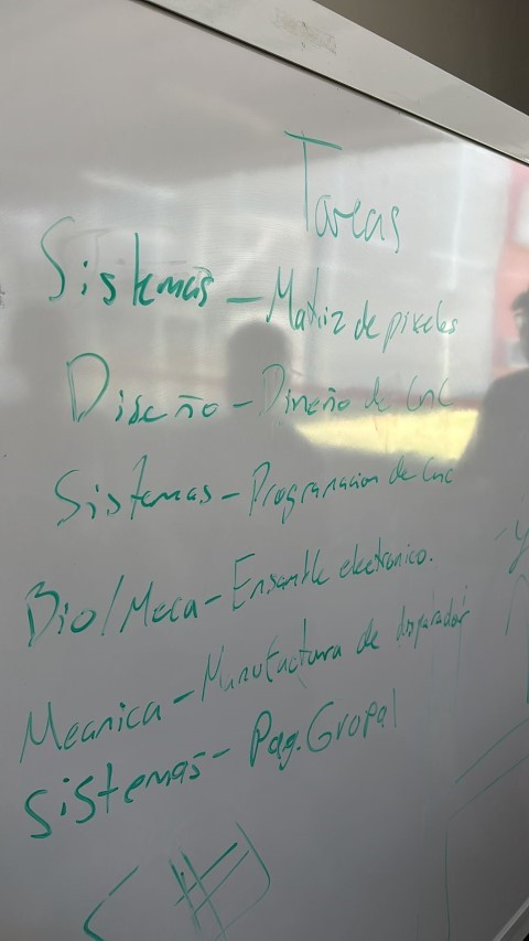
We decided to divide the tasks of our project based on the different areas of study we're pursuing. This approach really streamlined the process and made use of our individual strengths and expertise.
Andrea and Bernardo, leveraging their expertise in Industrial Design and nearing the completion of their studies, were instrumental in the design phase of our CNC machine. Their approach was methodical and meticulous, a reflection of their design philosophy and the rigorous training of their academic journey.
They began by conceptualizing the CNC machine, focusing on incorporating a user-oriented design that was functional and aesthetically pleasing. Their initial sketches laid the foundation for what would become a sophisticated piece of machinery.
They paid special attention to the inventory of available materials, considering how to best utilize the stock of electronic components and metal parts we had on hand. This foresight was pivotal in minimizing the need for additional resources, thereby optimizing our budget and project timeline.
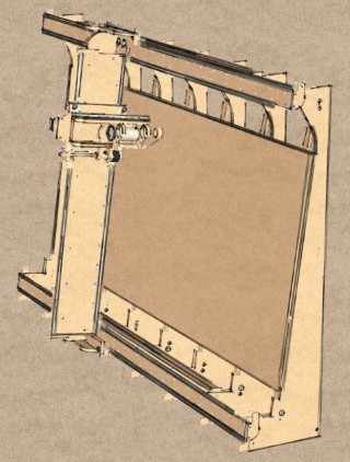
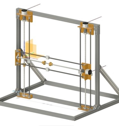
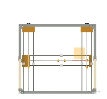
With a clear vision in place, Andrea and Bernardo transitioned to 3D modeling. Utilizing advanced CAD software, they translated their sketches into a digital form, creating a detailed representation of each component. This 3D model was crucial for visualizing the interplay between various parts and ensuring that the integrated paintball marker would operate within the desired parameters.
Designing each element with precision and care, they ensured that all the components, from the structural supports to the chassis and motor mounts, would come together seamlessly. Their design facilitated the manufacturing process, as each part could be edited and refined independently.

Once satisfied with the individual components, Andrea and Bernardo compiled them into an active design assembly file. This critical step allowed them to check for any misalignments or functional discrepancies, ensuring that the CNC machine would operate smoothly once assembled.
Their process was collaborative and iterative. They frequently revisited their designs, adjusting and improving upon them based on both theoretical knowledge and practical considerations. This level of detail and commitment ensured the accuracy and functionality of the CNC machine.
In the end, after rigorous testing and refinement, Andrea and Bernardo prepared the components for manufacturing. They exported the final designs and oversaw the production, ensuring that each part was fabricated to their exacting standards.
Guillermo worked closely with Andrea and Bernardoto develop the custom-built paintball gun for our CNC machine project. Their collaboration was pivotal in designing a system that was not only innovative but also adhered to stringent safety standards.
The process began with a detailed review of the mechanical and electronic requirements to ensure the paintball gun would integrate seamlessly with the CNC machine. Guillermo focused on the bioengineering aspects, particularly the ergonomics and safety features, while Andrea and Bernardo contributed their industrial design expertise to ensure the gun was user-friendly and aesthetically pleasing.
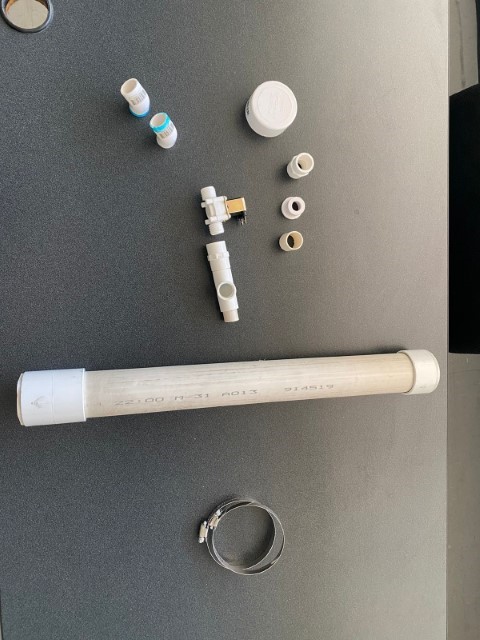
With Guillermo's input, the team selected materials and components that would be reliable and durable. They decided on a solenoid valve that could precisely control the firing mechanism, which was critical for the accuracy and repeatability needed in the CNC environment.
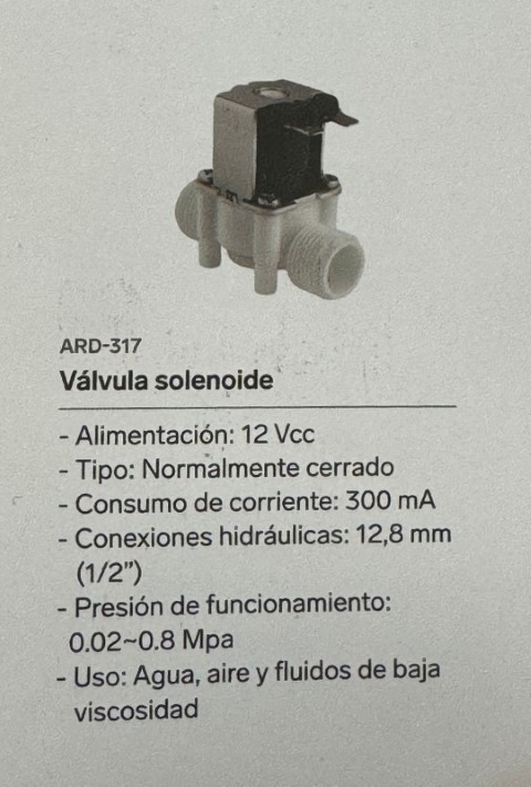
The solenoid valve has the following characteristics:
The normally closed type means that the valve is closed by default and only opens when electrically actuated, which is a common requirement for controlled pneumatic systems.
Andrea and Bernardo took the lead on the design, creating initial sketches and then developing them into a comprehensive set of blueprints. These designs outlined the structure of the gun, integrating the chosen solenoid valve and ensuring that all parts could be efficiently assembled.
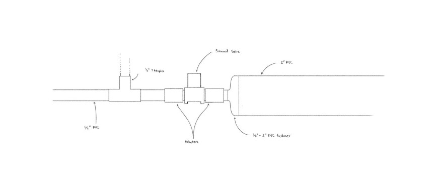
Guillermo's attention to detail was essential when it came to the placement and protection of the electronics, ensuring that the paintball gun's operation would be safe for both the machine and the operators. Meanwhile, Andrea and Bernardo's designs ensured that the gun would not only perform well but would also be a visually integrated component of the CNC machine.
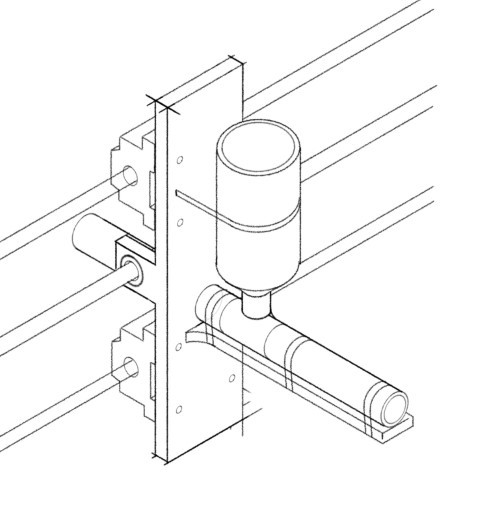
The end result was a custom-built paintball gun that embodied the team's commitment to excellence, innovation, and safety. The successful integration of this paintball gun into the CNC machine stood as a testament to the interdisciplinary collaboration and technical acumen of Guillermo, Andrea, and Bernardo.
In the era of digital creativity, pixel art emerges as a unique blend of minimalism and expressive detail. David Bojalil, drawing inspiration from the diverse world of pixel-based artistry, developed a Pixel Art Software that is designed to transform this digital art form into a tangible and interactive experience.
Our journey began with the mesmerizing techniques showcased in this video made by Joel Create which demonstrates a CNC Machine Paintball Gun similar to what we desired to do, which highlighted the intricate process of creating pixel art and its potential beyond traditional platforms and transforming it into G-Code.
The core idea was to bridge the gap between the pixel art creation process and a versatile tool that could simplify the design phase while providing a seamless way to analyze and utilize the artwork for the Paintball Gun to replicate.
Thus, the concept of leveraging Microsoft Excel as the canvas for our pixel art software was born.
Excel is not just a spreadsheet application; it's a canvas waiting to be explored. It offers:
Our Pixel Art Software transforms Excel into a dynamic pixel art studio, offering features such as:
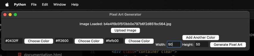
Our software, developed using Python with a Tkinter graphical user interface (GUI), leverages the powerful image processing capabilities of the PIL (Python Imaging Library) and the versatile data manipulation and storage features of OpenPyXL. The core functionality of the tool revolves around mapping the colors of an uploaded image to a predefined palette, generating pixel art that can be intricately controlled and modified to the artist's liking.

The tool's workflow begins with the user uploading an image.


Upon generating the pixel art, the software maps each pixel's color to the nearest match in the selected palette. This mapped image is then translated into an Excel spreadsheet, where each pixel is represented by a cell filled with the corresponding color.
Here is an example of how this process works:
First we will load the following image into our program:

Next, we will configure the program so that it can process it into the colors we want for the pixel art and the grid size, then we will click generate pixel art!
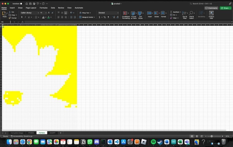
After that we will get our file and we will be able to see the following pixel art in Excel:

If we dig deeper, we can find that in that same excel file we can find different pages with the other layers of the pixel art. Here is a comparison between the yellow and blue layers of the example from above:
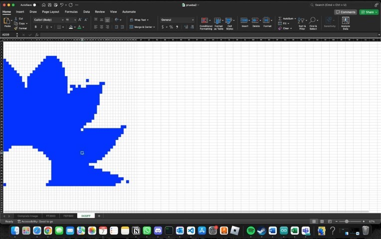
Integrating Excel into the pixel art creation process opens up a world of possibilities not only for our Paintball CNC but also for artists and creators. With each pixel represented as an Excel cell, users can easily adjust colors, create patterns, or even incorporate Excel's formulas and functions to add dynamic elements to their art. This level of precision and flexibility is unparalleled, making our tool an invaluable asset for both artistic expression and practical applications.
From the initial inspiration to the development of a fully-functional tool, our journey through the realms of creativity, programming, and data manipulation has culminated in a unique software that bridges the gap between art and technology. The ability to generate pixel art with such precision and to visualize it in an Excel spreadsheet not only democratizes the art creation process but also introduces a new medium for artistic exploration and expression.
As the CNC design reached completion and the 3D models were finalized, the next step was securing materials for the machine's construction. The structural frame was planned to be built using aluminum profiles, chosen for their strength, modularity, and ease of assembly.
Daniel A. Perez de la Mora, a researcher at Universidad Iberoamericana in Mexico City and member of the team, offered critical support by providing aluminum profiles, fasteners, and connection elements necessary for the build. His experience working with these materials also contributed to defining the best approach for assembly.

Due to time limitations and transport constraints, delivering the components to Puebla was not feasible. As a solution, several team members traveled to IBERO Mexico City to collect the materials directly, which also allowed them to engage with a different academic context and gain new perspectives.
Upon arrival, Daniel facilitated access to the materials and provided technical assistance in preparing them for transport. The aluminum profiles, initially in 6-meter lengths, were cut into 1.5-meter sections on-site to allow for easier handling and safer transportation back to Puebla.

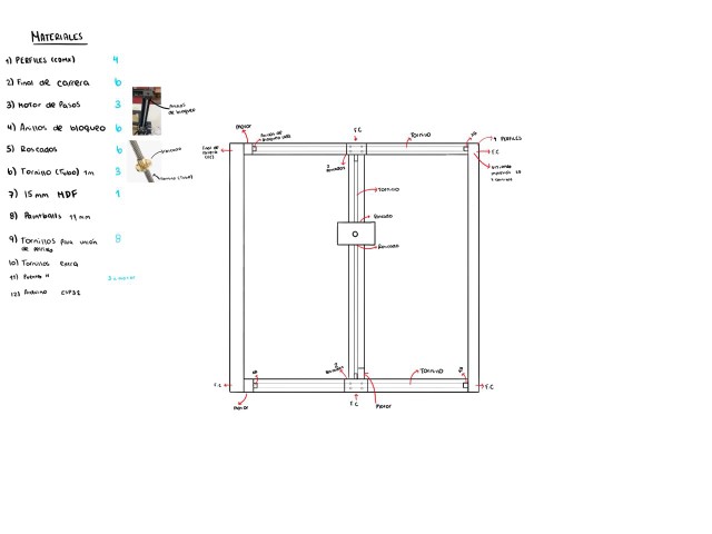
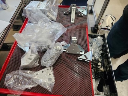
The Materials:
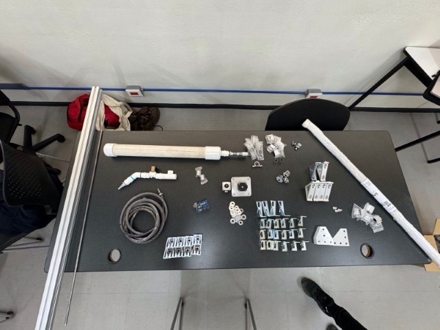
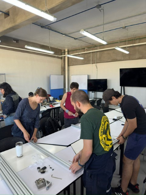
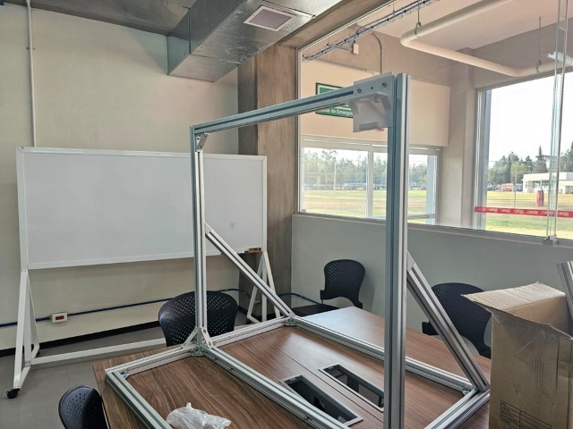
Once we acquired the materials, it was time to return to Puebla. Upon arrival, we commenced the assembly of the CNC machine, meticulously following the intricacies of the 3D design blueprint.
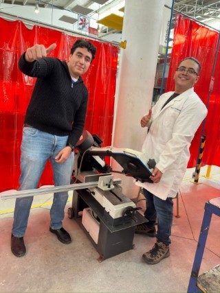
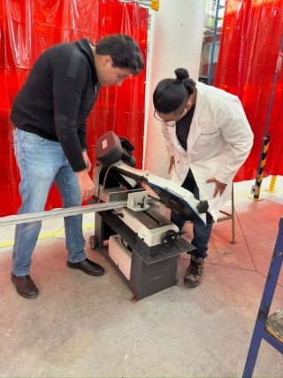
With the design blueprint and all required materials at hand, replicating the structure was a straightforward task. The next step involved adjusting the length of the aluminum profiles. Some of the profiles in our possession were longer than necessary, prompting a visit to the metal cutting band saw machine to trim them to the correct dimensions.
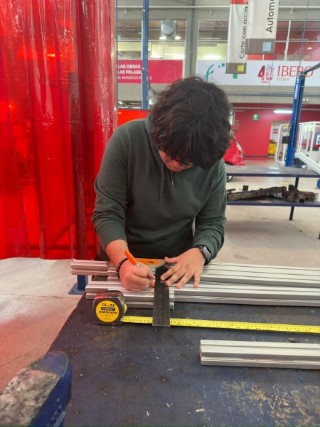
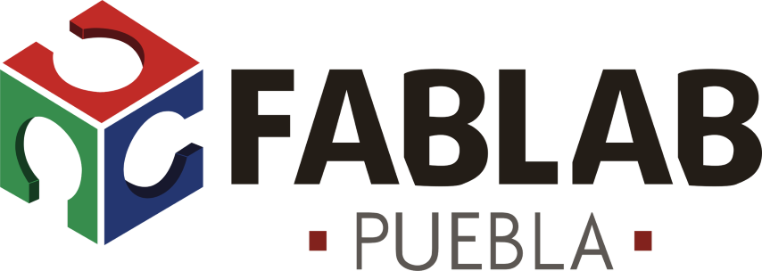
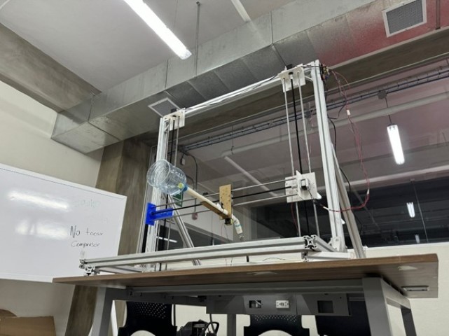
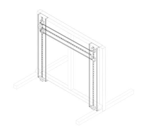
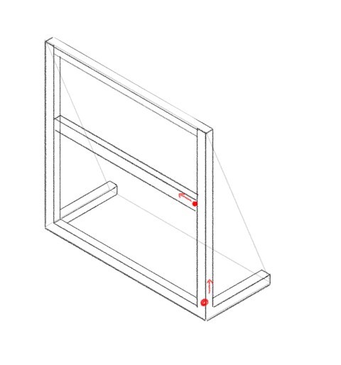
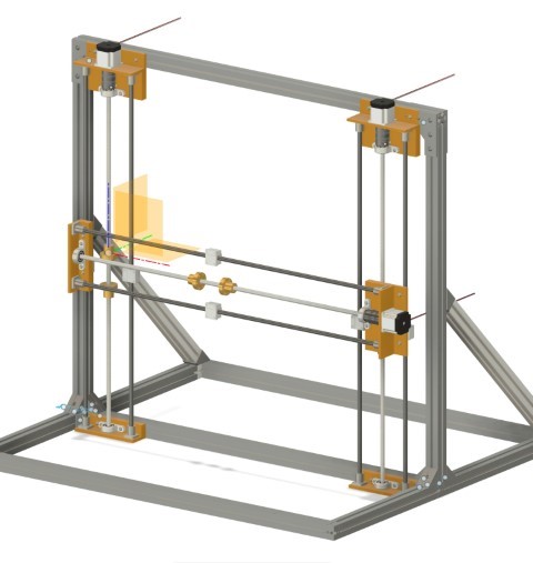
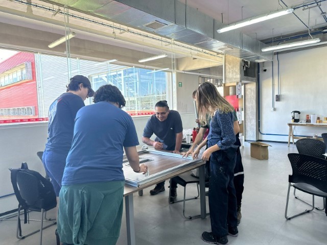
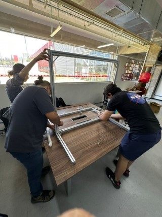
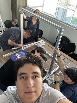
Once this was accomplished, we focused on constructing the skeleton of the CNC machine, marking the initial milestone in our project.
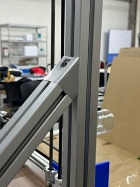
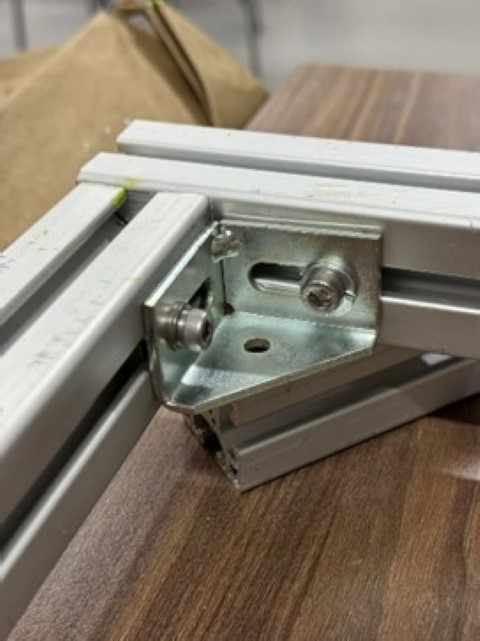
Unions:
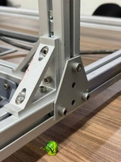
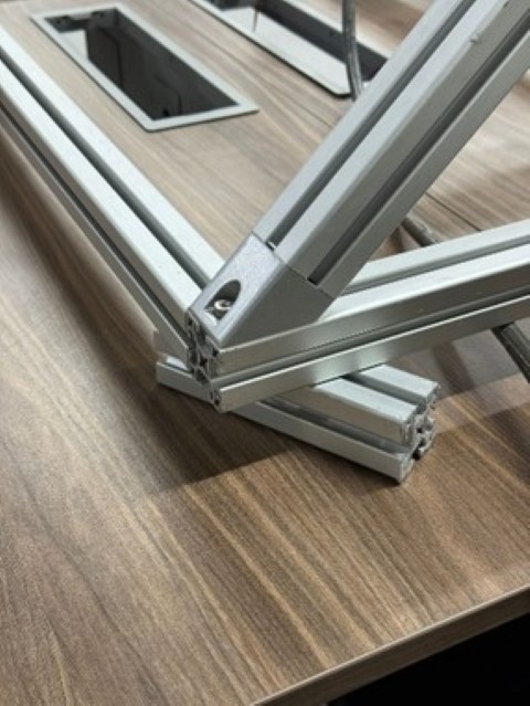
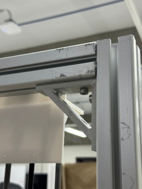
Skeleton Assembly:
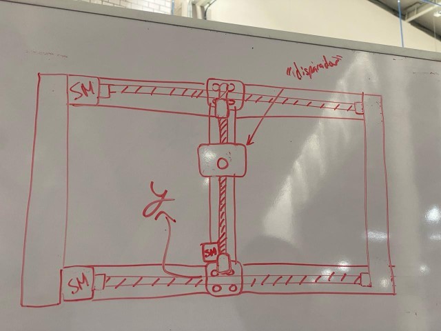
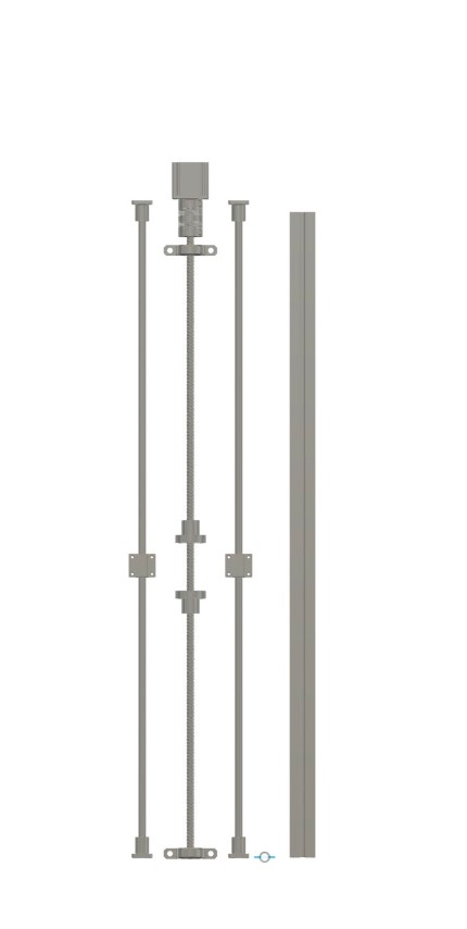
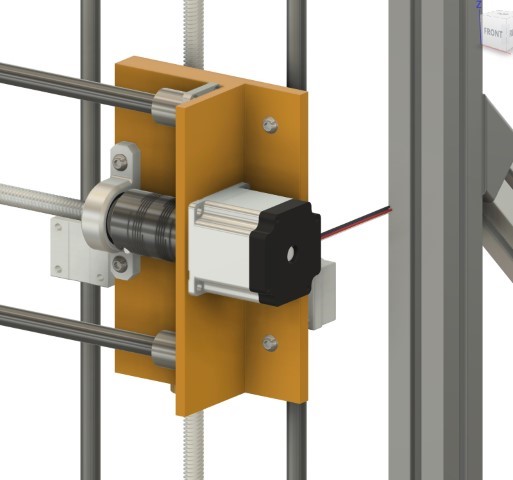
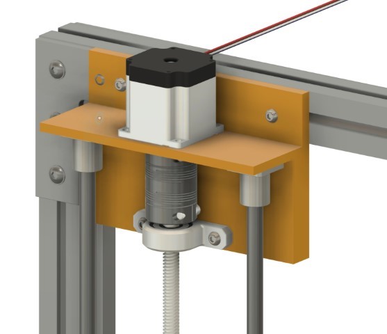
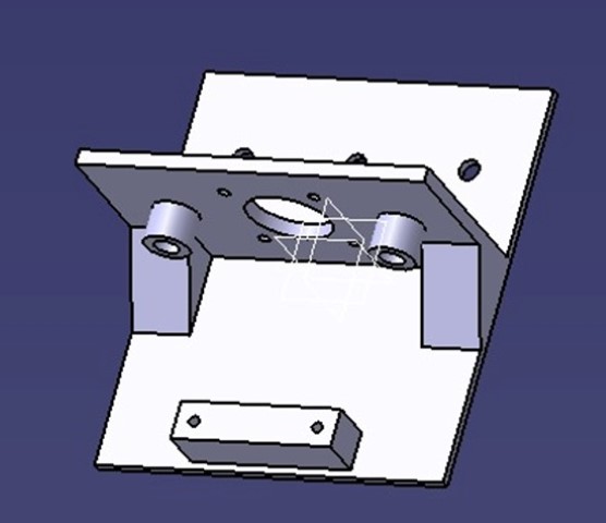
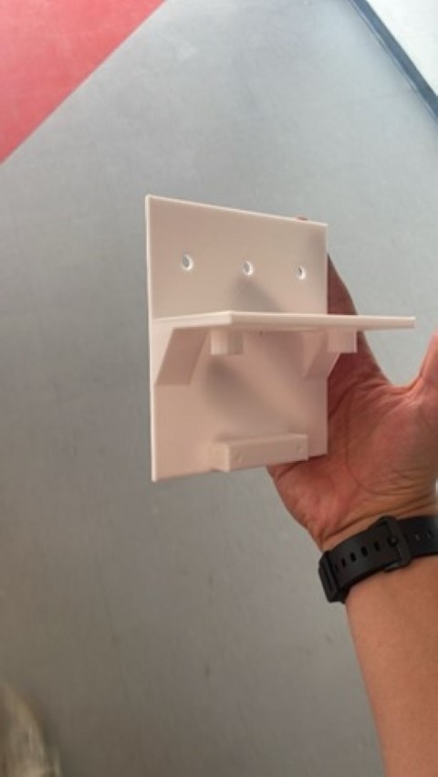
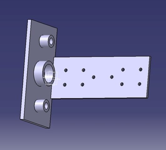
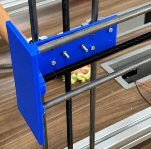
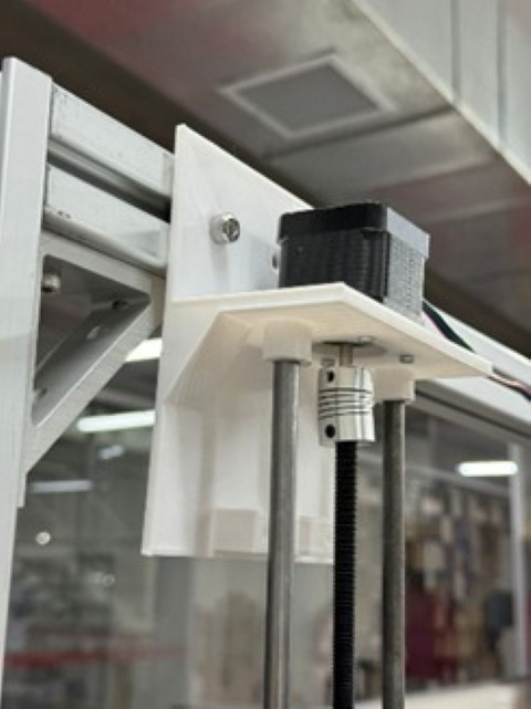
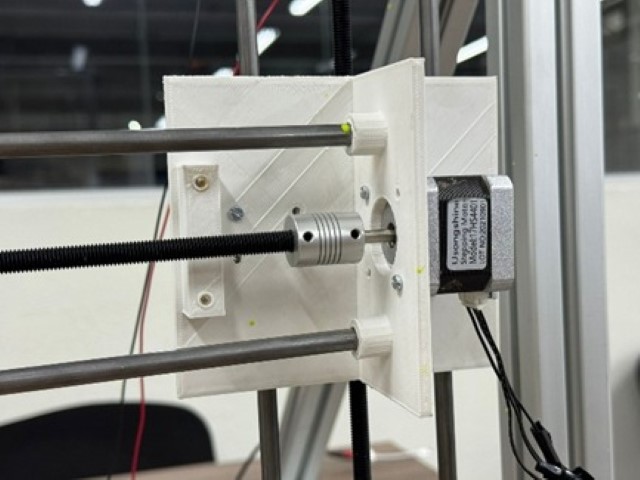
Once the skeleton was completed, we proceeded to 3D print various components for the electronic and mechanical moving axes. Stepper motors were employed to regulate the "Y" axis, governing the up and down movement, while another stepper motor controlled the "X" axis, managing the right and left movement. Upon revisiting our CNC's 3D model, we identified various supports designed to accommodate the motors and rods.
For the Y Axis:
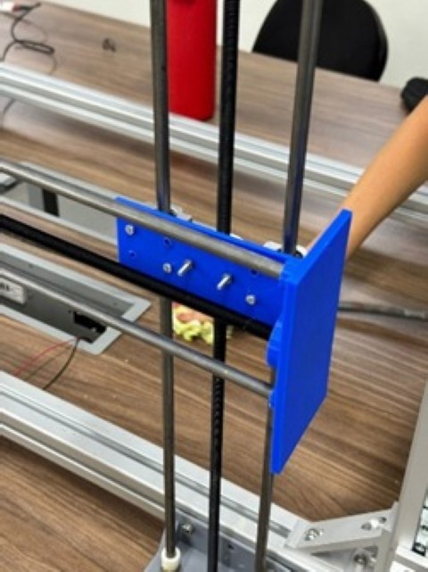
For the X Axis:
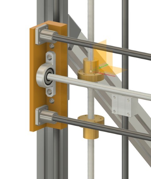
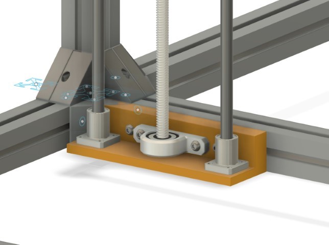
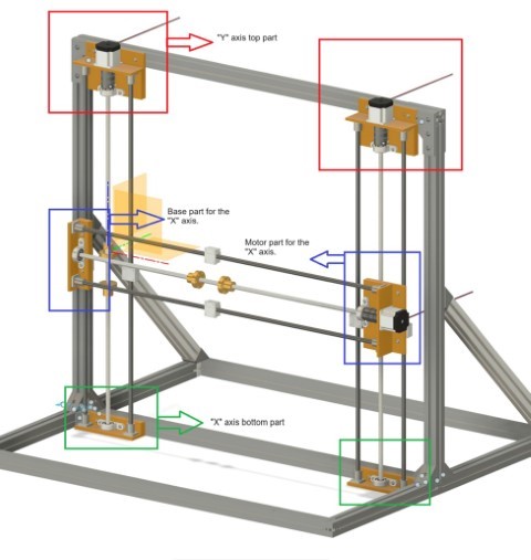 Important: An important detail to note is that both parts on the "X" axis will include an additional 3D printed component for the threaded rod. This additional part will feature an M8 nut, enabling both parts on the "X" axis to move freely up and down along the "Y" axis.
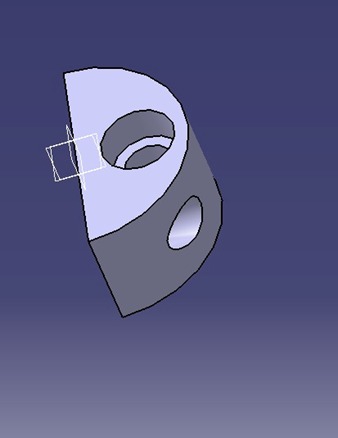
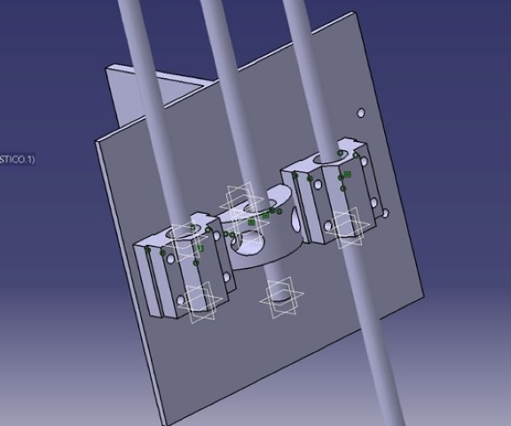
After establishing the mechanism for the movement in the two axes and identifying the necessary components, we commenced the final design phase for each part of the mentioned pieces.
X and Y axis top part final design:
Y axis bottom part final design:
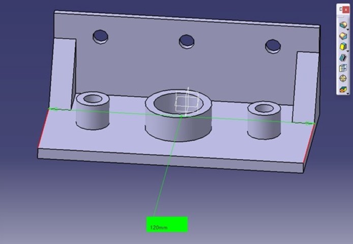
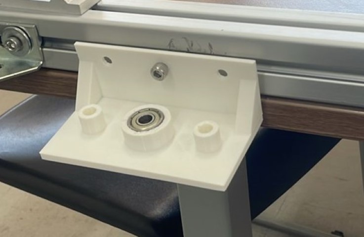
X axis base part final design:
As we awaited the completion of the printing process, which took approximately 10 hours in total, one team embarked on assembling the Paintball Gun, while another team delved into the programming aspect of the CNC machine.
With the design and simulations approved, we began manufacturing the parts. We used a combination of in-house fabrication techniques and sourced some specialized components from trusted vendors.
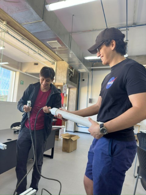
The assembly process required careful attention to detail. We followed the blueprints and assembly instructions from our 3D model, joining each component with precision.
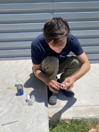
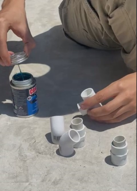
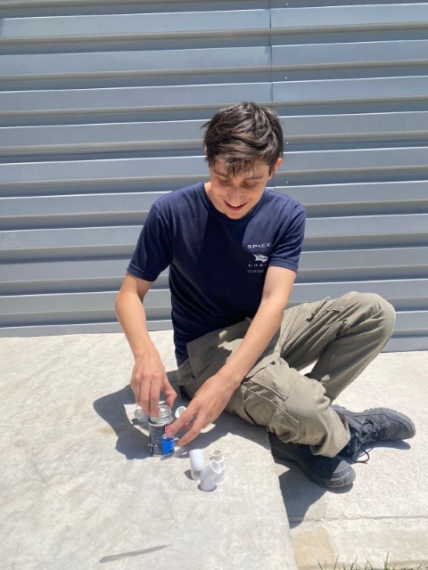
We mounted the firing mechanism and the solenoid valve. We integrated the electronic controls, making sure that all connections were secure and that there were no leaks in the pneumatic system.
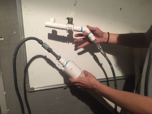
With the paintball gun assembled, we moved on to testing. We ran multiple trials to calibrate the firing mechanism, adjusting the pressure and timing to achieve the desired firing rate and accuracy. This step was iterative, with each test providing valuable data that we used to fine-tune the system like for example that the Paintball Gun needs 90 PSI of pressure in order to have a splat.

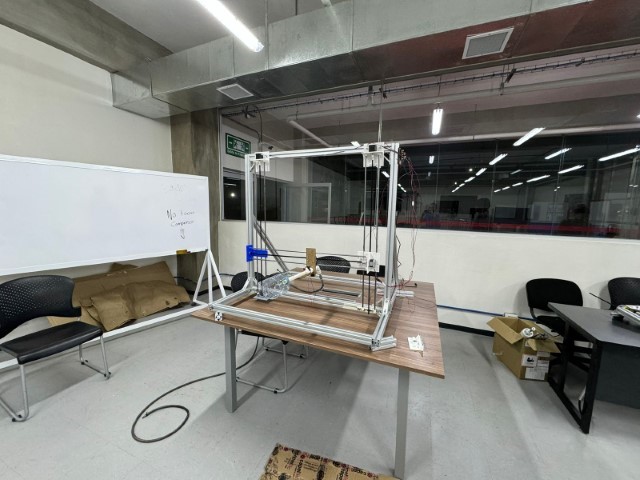
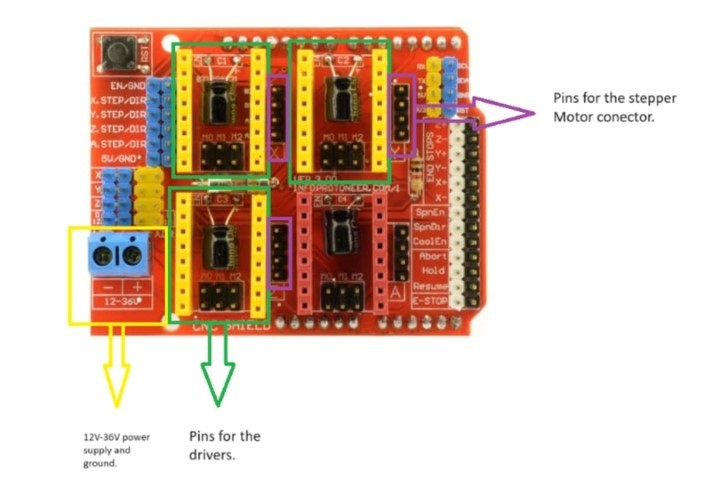
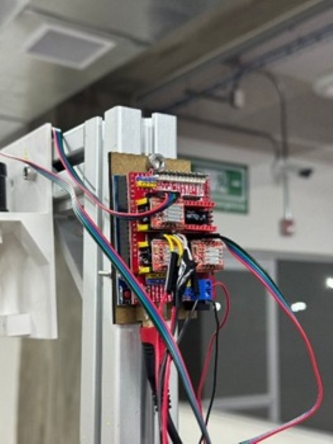
The Arduino CNC Shield is a compact board designed to facilitate the control of up to 4 stepper motors using your Arduino, owing to its shield format. It is compatible with both Pololu A4988 and Pololu DRV8825 power drivers (not included), offering versatile motor control capabilities. Additionally, it features all essential connections for integrating end stop switches, relay outputs, and various sensors. Fully compatible with the GRBL control firmware, this shield can be seamlessly utilized with any Arduino model, although the Arduino UNO is recommended for optimal performance.
To utilize the Arduino CNC Shield, we connected it to an Arduino UNO. The Arduino UNO is recommended for this purpose because its pins perfectly align with those of the Shield, ensuring seamless compatibility and optimal functionality.
To operate the stepper motors effectively, we required drivers for each motor. Each driver needed to be calibrated to a specific current limit based on the model of the motor being used. To calibrate the drivers, we first determined the reference voltage by dividing the required current of the motors (in this case, 1.2A for the Nema 17) by 2.5 ohms. This calculation yielded the reference voltage. Subsequently, we calibrated the drivers using a multimeter and adjusted a potentiometer knob accordingly.
Once the driver calibration is completed, we proceed to the connections on the shield. Initially, we supply power to the CNC Shield, which typically ranges from 12V to 36V. The specific voltage required depends on factors such as the number of drivers and the type of motors being controlled, which can affect the current needed. Subsequently, we utilize the pins designated for the drivers and the pins responsible for connecting to the stepper motor connections.

For the Arduino to work properly we need to install GRBL which will allow the Arduino to interpret G-Code.
To install GRBL into the Arduino we followed this steps:
In the realm of digital fabrication, the precision and versatility of CNC machinery are unparalleled.
Recognizing the potential for innovation within this space, David embarked on a project to not only control a CNC machine with high precision but to also integrate this control with the power of Excel. Our goal was ambitious: to build from scratch a CNC controller that goes beyond mere G-code sending. By leveraging Python and serial communication, we aimed to create a tool that could interpret Excel files as G-code, allowing for a more intuitive and accessible approach to CNC machining.
The idea was sparked by a desire to break free from the constraints of traditional G-code senders. While functional, these tools often lack the flexibility needed for custom projects. David wanted a solution that could seamlessly transition from digital design to physical creation, making the CNC machine more accessible to artists, designers, and hobbyists alike.
To achieve our vision, we developed a GUI application in Python, using PyQt for the interface and PySerial for communication with the CNC machine. This application serves not just as a G-code sender but as an innovative bridge between the Pixel Matrix digital design in Excel and physical machining.
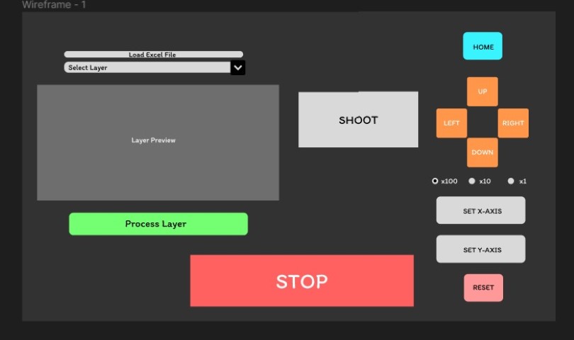
David designed on Figma a small GUI that served as insipiration to know the key functions for the software they were developing.
Building the application from scratch allowed us to tailor every aspect of its functionality to the specific needs of CNC machining. The decision to use Python, PyQt, and PySerial was driven by their flexibility, ease of use, and strong community support. Throughout the development process, we focused on creating an intuitive user interface that could accommodate both simple and complex machining tasks.
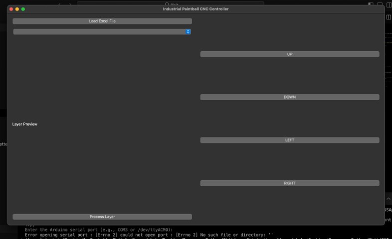
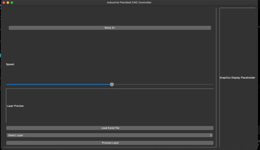
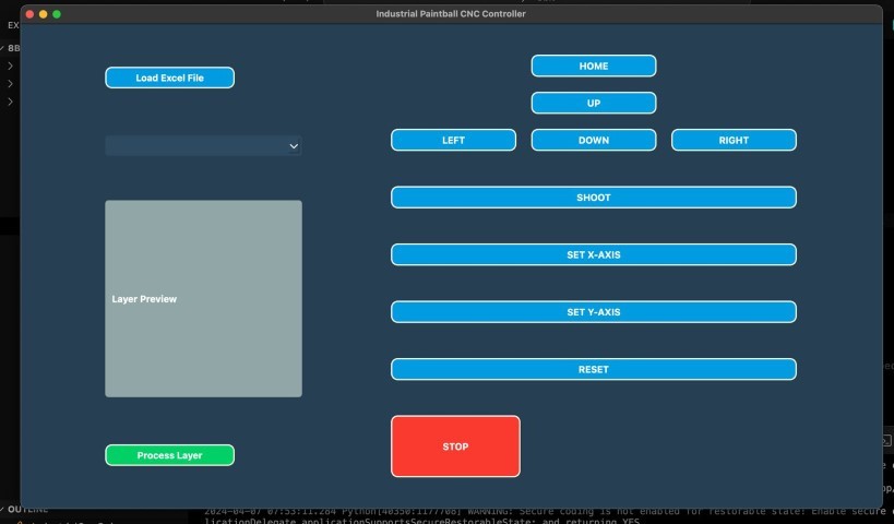
Although the last Conceptual User Interface was the one David wanted the most, it was too complicated to program due that there were extra buttons and adding a Stop button that worked would be more work that needs to be done to the code. Thus, we decided that this GUI was the most optimal:
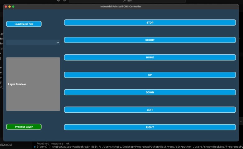
By using Excel as an intermediary design tool, we have opened up CNC machining to a wider audience, making it more accessible and intuitive. Our custom G-code sender, built entirely from scratch, stands as a testament to the potential for innovation in the field of digital fabrication. This project not only showcases the capabilities of Python and serial communication but also illustrates the endless possibilities that arise when we rethink traditional processes and tools.
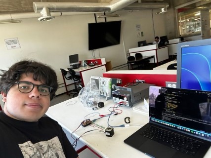
First, we did a “manual test” using our own interface, we observed how the different axis moved at different revolutions and finally established a 20-unit step for our motors.
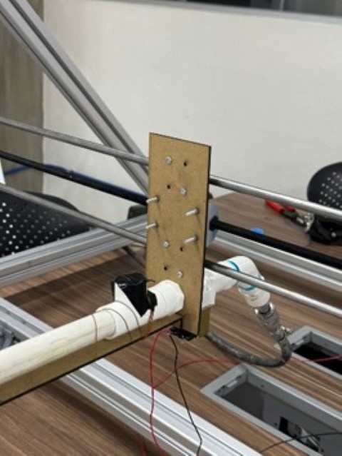
Then we did a launcher test to see how well our paintball launcher worked:
Finally, we did an automatic test by uploading a simple pixelated drawing using our interface. Our test was very simple mostly because here in Puebla the places that sell paintballs are few and we didn’t get many so we had to divide them between the different test we did with the launcher.
After this test we conclude that to get a more defined shape we need to control more the explosion of the paintball. We are still working with different ideas that could improve the launcher system of our CNC.
In conclusion, the journey of designing and constructing a custom-built paintball gun for our CNC machine was a comprehensive display of interdisciplinary collaboration and technical skill. From the initial concept to the final integration, every step was approached with a meticulous attention to detail and a focus on innovation.
The successful completion of this project not only signifies the creation of a fully functional and integrated paintball gun within a CNC machine but also stands as a testament to the power of collaborative ingenuity in overcoming logistical challenges and achieving a common goal. The experience garnered and the knowledge exchanged during this project will undoubtedly resonate in our future endeavors as engineers and designers.