Electromechanical Jacquard machine
For my final proyect I want to creat a prototipe for an Electromechanical Jacquard machine.
Research
Developed in 1804 by Joseph-Marie Jacquard. The Jacquard loom is a weaving machine that lets the user create textiles with complex patterns using perforated plates that function as guides to tell the machine how to weave the treads[1]. Of course, this explanation is vague and doesn´t really explain what it actually does. In order to demonstrate how this machine works I´ve found this video created by Macclesfield Museums. Link to chanel
Understanding the Jacquard mechanism is only the beginning. Now the question is: How can we implement an electromechanical mechanism? And why?. First of all, we need to remember that the Jacquard mechanism is an ancestor to a computer, in the sense that it works with a binary algorithm, the tread stays down or it goes up. However, due to the mechanical function of the machine, the patterns that it can create in the tapestry are limited, in order to make a complex pattern you need an industrial-sized machine. But if there were a way to digitalize the way it makes the patterns it could result in a machine capable of complex designs while being the size of a desk.
Sketches
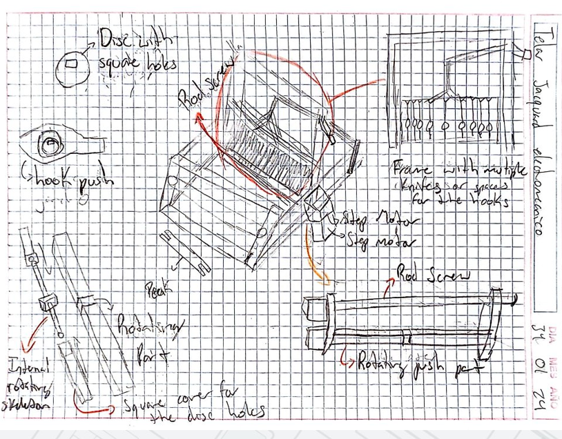
There are two initial problems with my sketch. The first one is the space I need to implement the mechanical and electrical components, the machine needs enough space for the treads to pass from one side to the other, and the same goes for the frames. My initial solution would be to make it taller, so the electromechanical implements end up in the base of the machine. The second problem is more on the mechanical part, so far the sketch is based on my knowledge of the Jacquard machine and basic mechanical principles. But I have no idea how it would actually function on a real prototype. I need to further understand the Jacquard machine in order to create a more accurate design.
Second sketch and new ideas
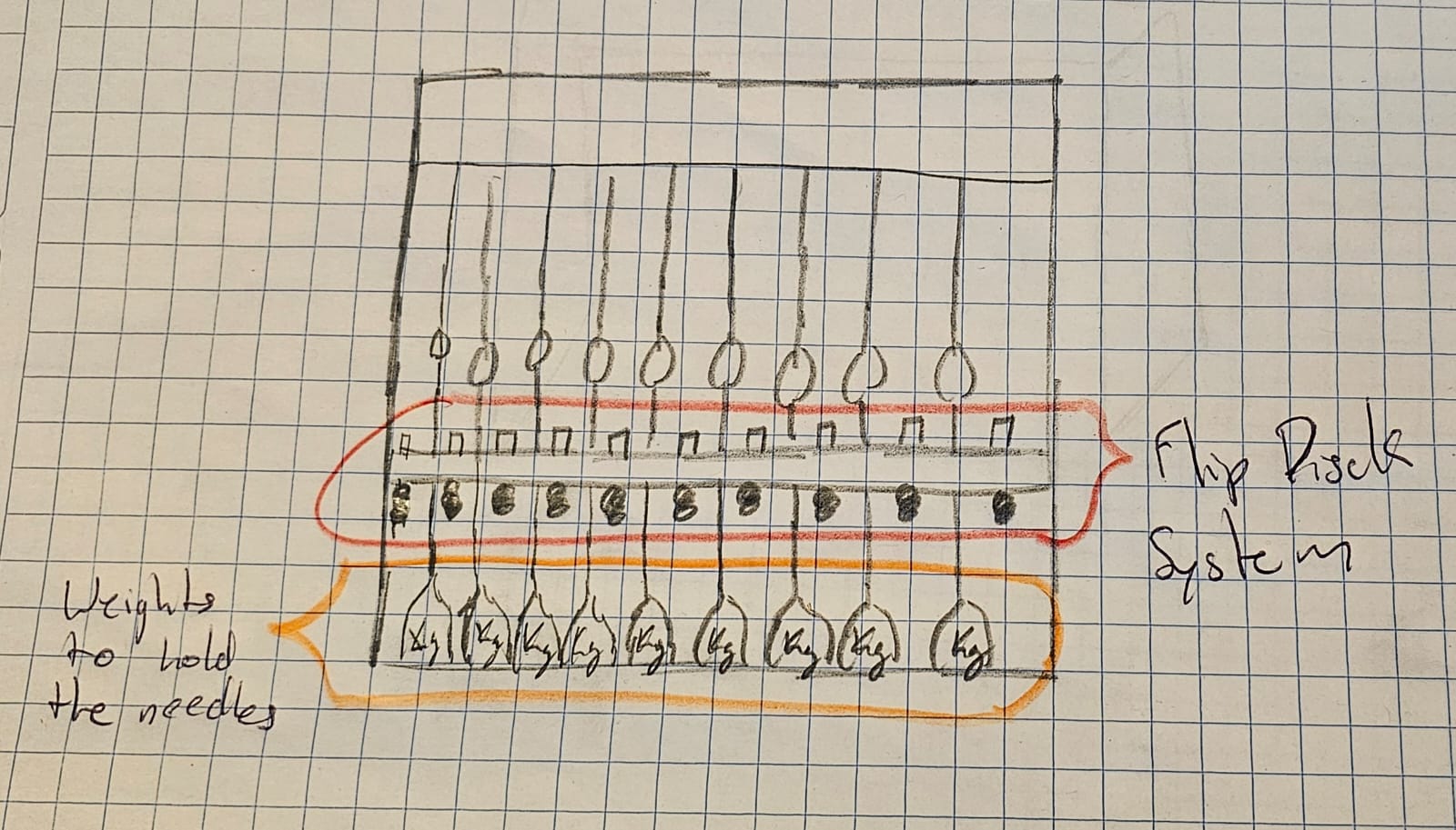
Talking with my instructors about the ideas for the final project I was presented with a new idea for the mechanism, as I explained before, the Jacquard loom works with perforated plates that determine which treads stay down or go up. This new idea consists of using a system similar to the flip discs, the flip disc is an electromechanical dot matrix display that's usually used to create changing signs and displays, like a mechanical version of LED signs, it was commonly used in the USA's school buses that had signs, using the flip-disc matrix they could write different thing's like warning signs. I'll leave the link to a website that further explains how flip-discs work. Flip-disc website
Sketch 2 & New mechanism
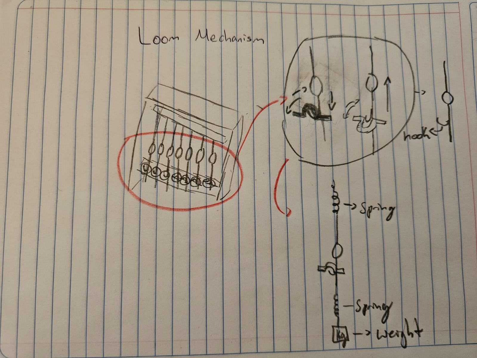
The new design changes the mechanism that controls which tread stays down and which tread goes up. The treads pass through a "needle" this needle has a hook that will get trapped in the disc. This way I can precisely select which treads stay down and which treads go up.
Midterm & advances on the project.
At this point, I had some of the mechanical parts of the loom done since we were reaching the end of the Fab Academy classes I had an idea of what I needed to do and in wat order I wanted to do it.
Schedule for the final project
| Week's | Task |
|---|---|
| From the 6th to the 10th of Agust | PCB design and soldering |
| From the 13th to the 17th | Loom design and MDF cutting and assembling.. |
| From the 20th to the 24th | First loom test, mechanical and digital prototype testings. |
| From the 27th to the 31st | Polished mechanical system, functional digital interface, and loom testing. |
| From the 3rd to the 7th of June | Prepare final project video and presentation. |
Some of these week may seem rushed but I had some bits of the task's already done so it was faster to finish them.
I2C
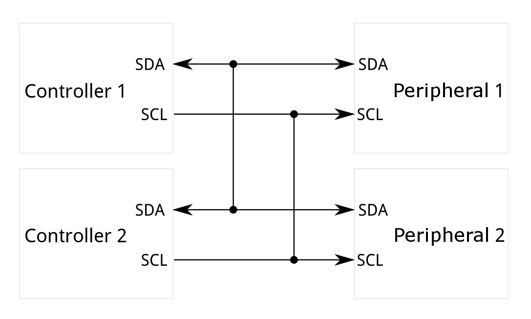
I2C, or Inter-Integrated Circuit, is a communication protocol commonly used to connect multiple integrated circuits on the same board. It uses two lines for communication: SDA (Serial Data) and SCL (Serial Clock).
In an I2C connection, there are two main roles: the controller and the peripheral.
- Controller (Primary): This device initiates communication and controls the clock line (SCL). It sends commands and data to the peripheral devices.
- Peripheral (Secondary): These devices respond to the controller. They can send data back when requested but do not initiate communication on their own.
How it Works
- Start Condition: The controller sends a start condition by pulling the SDA line low while SCL is high, signaling the beginning of a communication session.
- Addressing: The controller then sends the 7-bit address of the peripheral it wants to communicate with, followed by a read/write bit. This address allows multiple devices to share the same bus.
- Acknowledgment: The peripheral with the matching address responds by pulling the SDA line low (acknowledge bit).
- Data Transfer: Data is transferred between the controller and the peripheral. Each byte sent is followed by an acknowledgment from the receiver.
- Stop Condition: The controller ends the communication by releasing the SDA line while SCL is high, signaling the stop condition.
PCBs
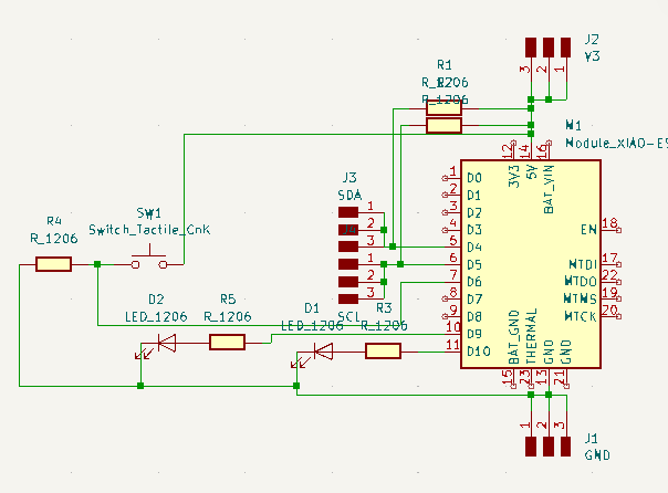
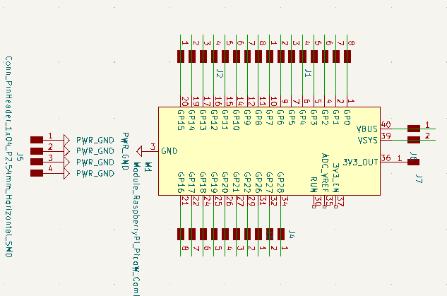
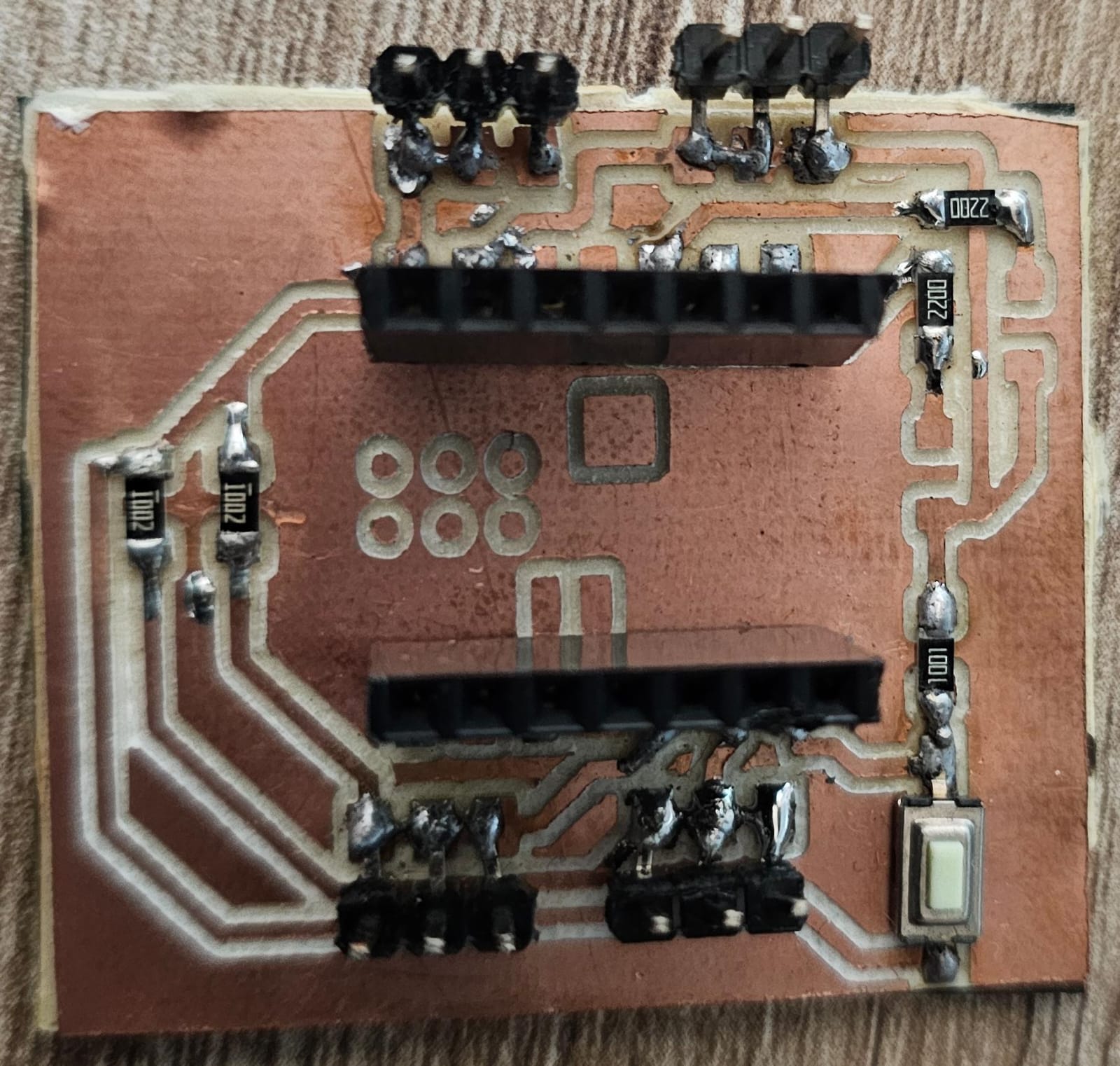
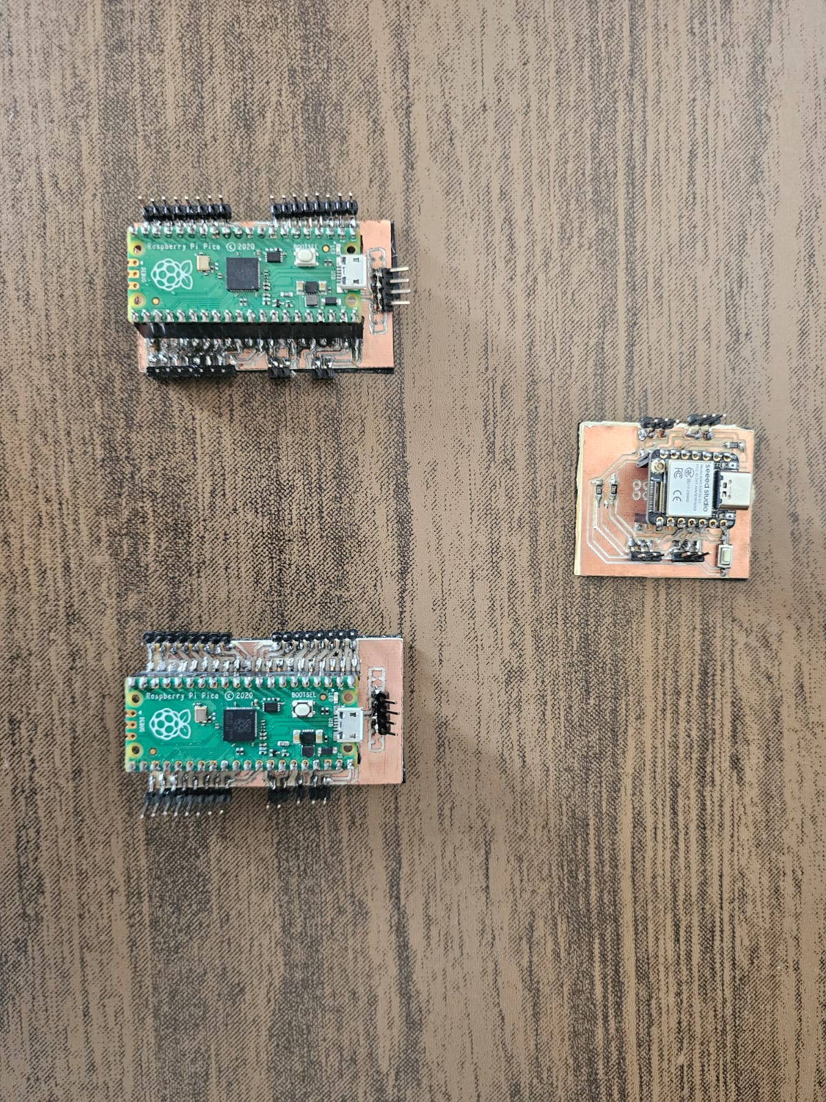
For this week's assignment, I designed two PCBs that will be used in my final project. I made one for the XIAO-2040, I'll use this one as my controller. The other one I made for the Raspberry PI pico 2040, this one is the peripheral.
Schematics and design
- XIAO-ESP32
- Raspberry PI pico 2040
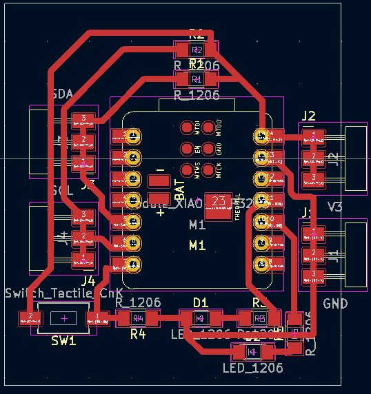
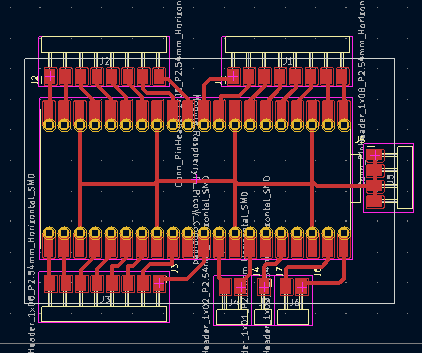
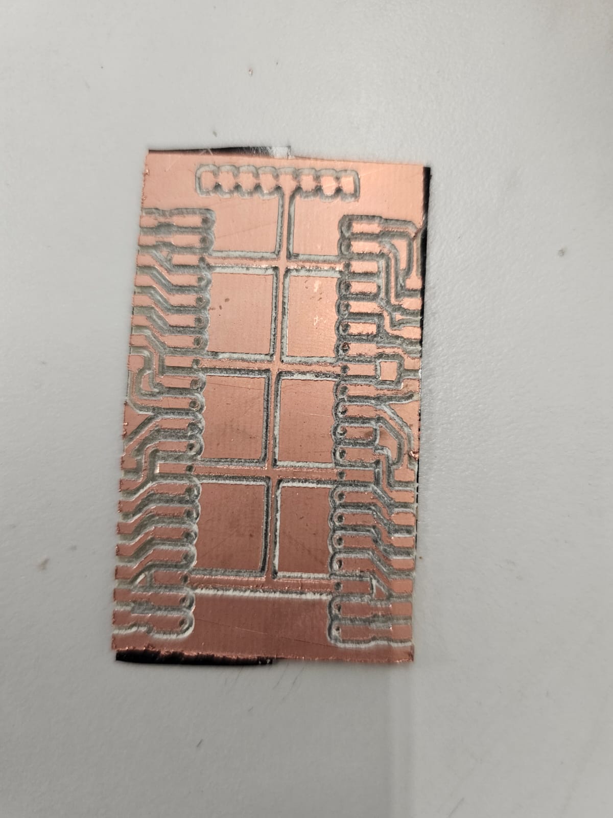
PCBs production
Coding
The hardest part of the code was to make a Python code that reads Excel cells with a preassigned value and sends them to the Arduino controller.
                    Python controler
                        import openpyxl
                        import serial
                        import time

                        puerto = '/dev/ttyUSB0'  # Replace with correct port
                        baudios = 9600
                        ser = serial.Serial('COM11', 115200, timeout=1)

                        # Wait a moment to communicate with arduino
                        time.sleep(2)

                        # Name of Excel file
                        archivo_excel = 'hello_world'

                        # Upload work book
                        wb = openpyxl.load_workbook("hello_world.xlsx")

                        # Select work sheet
                        ws = wb.active

                        # Read the cell value
                        value_range = ws ['A1':'P74']
                        text = []
                        indice = 0
                        for a, b, c, d, e, f, g, h, i, j, k, l, m, n, o, p in value_range:
                            text.append(str(a.internal_value) + str(b.internal_value) + str(c.value) + str(d.value) + str(e.value) + str(f.value) + str(g.value) + str(h.value) + str(i.value) + str(j.value) + str(k.value) + str(l.value) + str(m.value) + str(n.value) + str(o.value) + str(p.value))
                            #print(text)

                        #Close workbook after its done.
                        wb.close()
                        print(text[6])

                        dato = text + ';' #Ends the string
                        ser.write(dato.encode())
The Arduino codes were pretty simple, the first code is for the controller, it just receives data from the python code and depending on what it receives sends the instruction to the primary or secondary peripheral.
                    Controller Code
                            #include
                            String msj = " ";
                             byte diskP[] = {'A','B','C','D','E','F','G','H','I','J','K','L','M','N','O','P'};
                             byte diskN[] = {'a','b','c','d','e','f','g','h','i','j','k','l','m','n','o','p'};

                            // the setup function runs once when you press reset or power the board
                            void setup() {
                              // initialize digital pin LED_BUILTIN as an output.
                              Serial.begin(115200);
                               Wire.begin();
                            }

                            // the loop function runs over and over again forever
                            void loop() {

                              if(Serial.available()>0){
                                Serial.print("Dato recibido");
                                msj += Serial.readStringUntil(';'); //Receives a string of data from the Python code
                                for(int i=0; i<8; i++){
                                  Wire.beginTransmission(1);  // Convey to primary p[eripheral]
                                  if(msj[i]=='1')
                                  {
                                    Wire.write(diskP[i]);
                                  }
                                  else if(msj[i]=='0')
                                  {
                                    Wire.write(diskN[i]);
                                  }
                                  Wire.endTransmission();
                                }
                                for (int i=8; i<16; i++){
                                  Wire.beginTransmission(2);  // Convey to secondary peripheral
                                  if(msj[i]=='1')
                                  {
                                    Wire.write(diskP[i]);
                                  }
                                  else if(msj[i]=='0')
                                  {
                                    Wire.write(diskN[i]);
                                  }
                                  Wire.endTransmission();
                                }
                              }
                                // wait for a second
                            }
The peripherals just received data and executed a certain command depending on what it receives.
#include
const int Ap = 0;
const int As = 1;
const int Bp = 2;
const int Bs = 3;
const int Cp = 4;
const int Cs = 5;
const int Dp = 6;
const int Ds = 7;
const int Ep = 8;
const int Es = 9;
const int Fp = 10;
const int Fs = 11;
const int Gp = 12;
const int Gs = 13;
const int Hp = 14;
const int Hs = 15;
void setup() {
// initialize digital pin LED_BUILTIN as an output.
pinMode(Ap, OUTPUT);
pinMode(As, OUTPUT);
pinMode(Bp, OUTPUT);
pinMode(Bs, OUTPUT);
pinMode(Cp, OUTPUT);
pinMode(Cs, OUTPUT);
pinMode(Dp, OUTPUT);
pinMode(Ds, OUTPUT);
pinMode(Ep, OUTPUT);
pinMode(Es, OUTPUT);
pinMode(Fp, OUTPUT);
pinMode(Fs, OUTPUT);
pinMode(Gp, OUTPUT);
pinMode(Gs, OUTPUT);
pinMode(Hp, OUTPUT);
pinMode(Hs, OUTPUT);
// We join this code with the I2C and establish it as the peripheral 1.
Wire.begin(1);
}
// the loop function runs over and over again forever
void loop() {
if(Wire.available() > 0) {
char command = Wire.read(); // Reads the data send by the controller
if (command = 'A'){
Serial.print("+Disk1");
digitalWrite(Ap, HIGH);
digitalWrite(As, LOW);
delay(500);
}
else if (command = 'a'){
Serial.print("-Disk1");
digitalWrite(Ap, LOW);
digitalWrite(As, HIGH);
delay(500);
}
else if (command = 'B'){
Serial.print("+Disk2");
digitalWrite(Bp, HIGH);
digitalWrite(Bs, LOW);
delay(500);
}
else if (command = 'b'){
Serial.print("-Disk2");
digitalWrite(Bp, LOW);
digitalWrite(Bs, HIGH);
delay(500);
}
else if (command = 'C'){
Serial.print("+Disk3");
digitalWrite(Cp, HIGH);
digitalWrite(Cs, LOW);
delay(500);
}
else if (command = 'c'){
Serial.print("-Disk3");
digitalWrite(Cp, LOW);
digitalWrite(Cs, HIGH);
delay(500);
}
else if (command = 'D'){
Serial.print("+Disk4");
digitalWrite(Dp, HIGH);
digitalWrite(Ds, LOW);
delay(500);
}
else if (command = 'd'){
Serial.print("-Disk4");
digitalWrite(Dp, LOW);
digitalWrite(Ds, HIGH);
delay(500);
}
else if (command = 'E'){
Serial.print("+Disk5");
digitalWrite(Ep, HIGH);
digitalWrite(Es, LOW);
delay(500);
}
else if (command = 'e'){
Serial.print("-Disk5");
digitalWrite(Ep, LOW);
digitalWrite(Es, HIGH);
delay(500);
}
else if (command = 'F'){
Serial.print("+Disk6");
digitalWrite(Fp, HIGH);
digitalWrite(Fs, LOW);
delay(500);
}
else if (command = 'f'){
Serial.print("-Disk6");
digitalWrite(Fp, LOW);
digitalWrite(Fs, HIGH);
delay(500);
}
else if (command = 'G'){
Serial.print("+Disk7");
digitalWrite(Gp, HIGH);
digitalWrite(Gs, LOW);
delay(500);
}
else if (command = 'g'){
Serial.print("-Disk7");
digitalWrite(Gp, LOW);
digitalWrite(Gs, HIGH);
delay(500);
}
else if (command = 'H'){
Serial.print("+Disk8");
digitalWrite(Hp, HIGH);
digitalWrite(Hs, LOW);
delay(500);
}
else if (command = 'h'){
Serial.print("-Disk8");
digitalWrite(Hp, LOW);
digitalWrite(Hs, HIGH);
delay(500);
}
else{
digitalWrite(Ap,LOW);
digitalWrite(As,LOW);
digitalWrite(Bp,LOW);
digitalWrite(Bs,LOW);
digitalWrite(Cp,LOW);
digitalWrite(Cs,LOW);
digitalWrite(Dp,LOW);
digitalWrite(Ds,LOW);
digitalWrite(Ep,LOW);
digitalWrite(Es,LOW);
digitalWrite(Fp,LOW);
digitalWrite(Fs,LOW);
digitalWrite(Gp,LOW);
digitalWrite(Gs,LOW);
digitalWrite(Hp,LOW);
digitalWrite(Hs,LOW);
}
}
delay(30);
}
The second peripheral is the same code but with different variables
System integration
The design of the electromechanical loom was based on the looms we have in Iberto Puebla that are used in textile design and other similar careers. The thing is that it needed to be modified to fit the electrical parts. Here's a basic sketch explaining the distribution of the loom.
3D Model
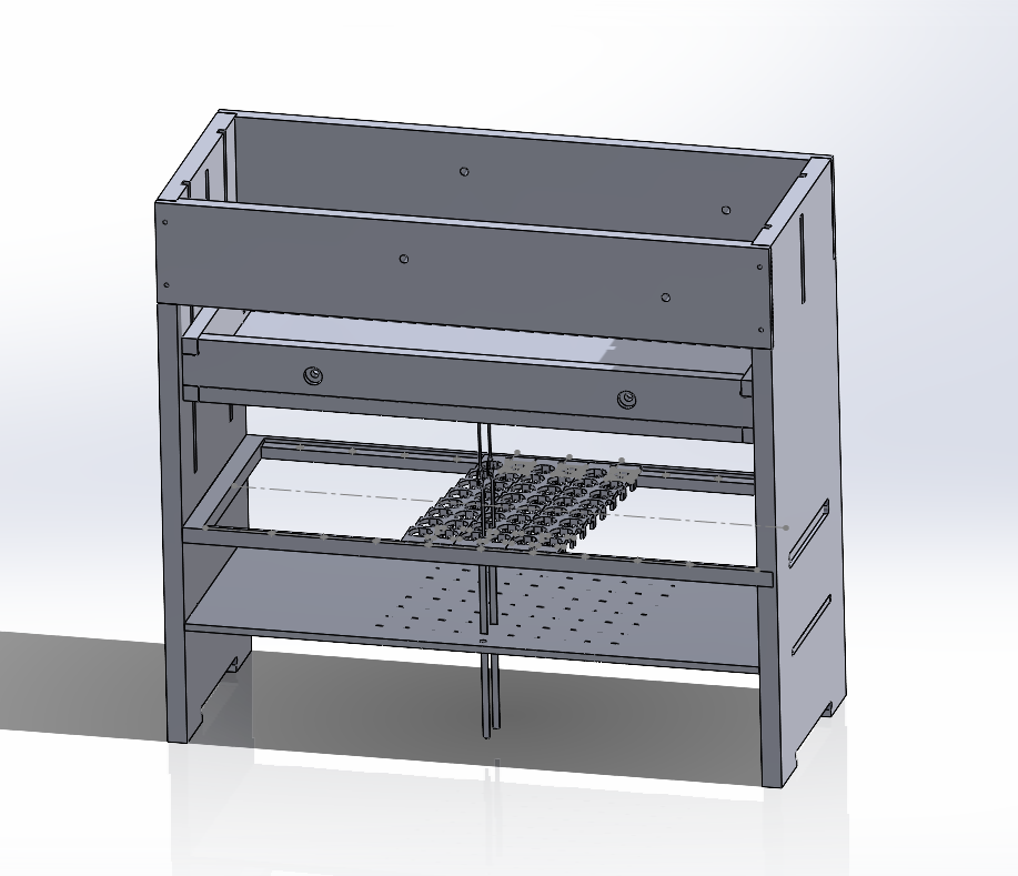
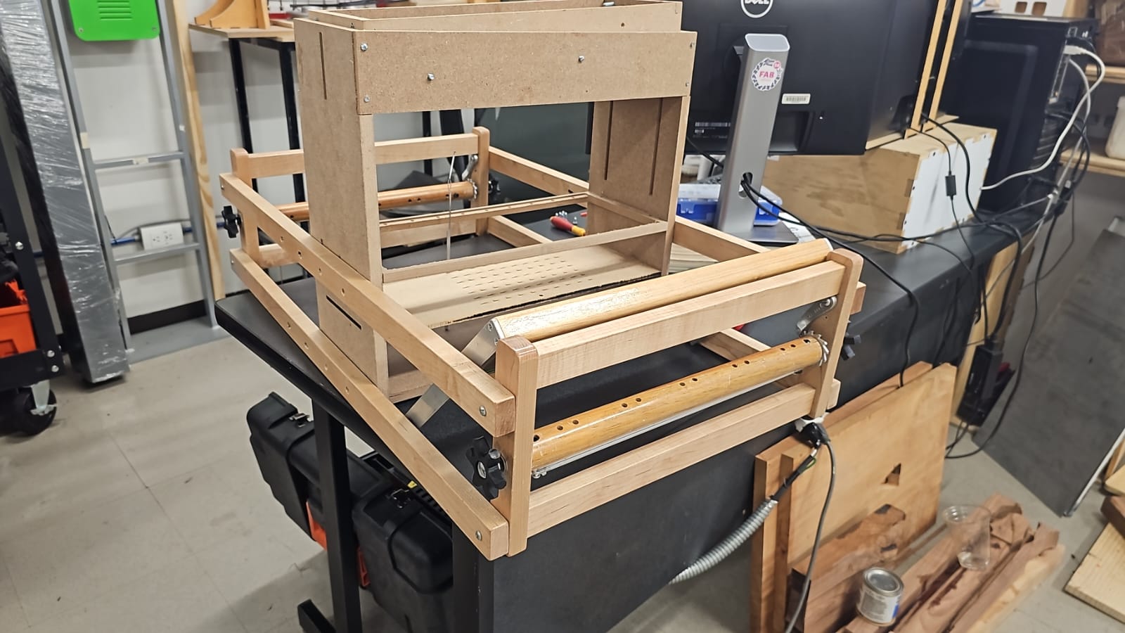
The frame is the support for the main electronics and mechanical system, the frame consists of a bed that traps the heddles and guides their descent and ascend. Then there's a support where the flip-disc mechanism is placed, this is the part that controls the movement of the heddles. Finally, there's the top "drawer", this part is in charge of "locking" the heddles. The drawer has a metal sheet at the bottom, each heddle has a magnet at the tip that attaches to the metal sheet of the drawer. So all the heddles get attached but only the ones that aren't locked by the flip-disc mechanism will go up.
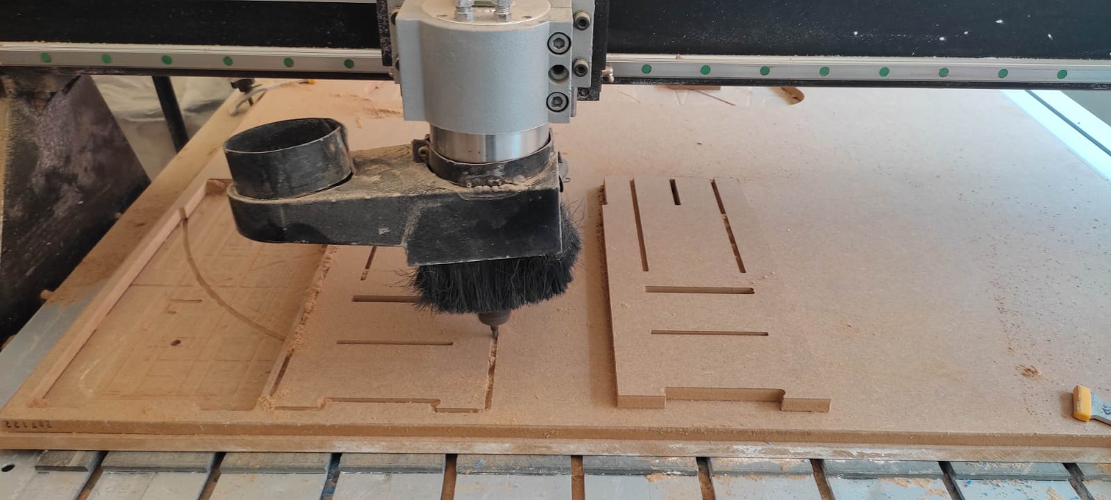
Once the final design was finished it was time to start the production of the frame. The frame is made from 15mm MDF machined in Ibero Puebla's CNC router.
Mechanical design and production
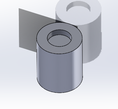
The mechanism that locks the heddles into place is inspired by the flip-disc. The first idea was to buy a flip-disc module but in the end, I didn't find where to get one. Due to this, the only option was to make one specifically for this project. The design for the mechanical system is being patented, due to this we can't show it in great detail. The production of this mechanism consists of 2 parts, 3D printing and coil production. The base of the mechanism and the "flip-disc" are 3D printed, for the coils we use a machine that was built here in Ibero Puebla. The machine rolls up copper wire in a 25-mm screw. Once the machine finishes the process it leaves the coil with two different ends. Wires are soldered to these ends, this way the coils can be used as electromagnets, and polarities can be changed using drivers or diodes. Once the wires are soldered the coil is covered in thermofit to protect the copper wire.
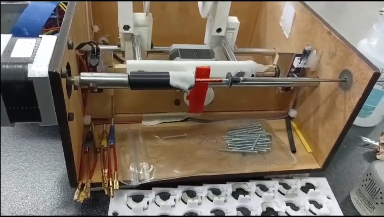
Mechanism result
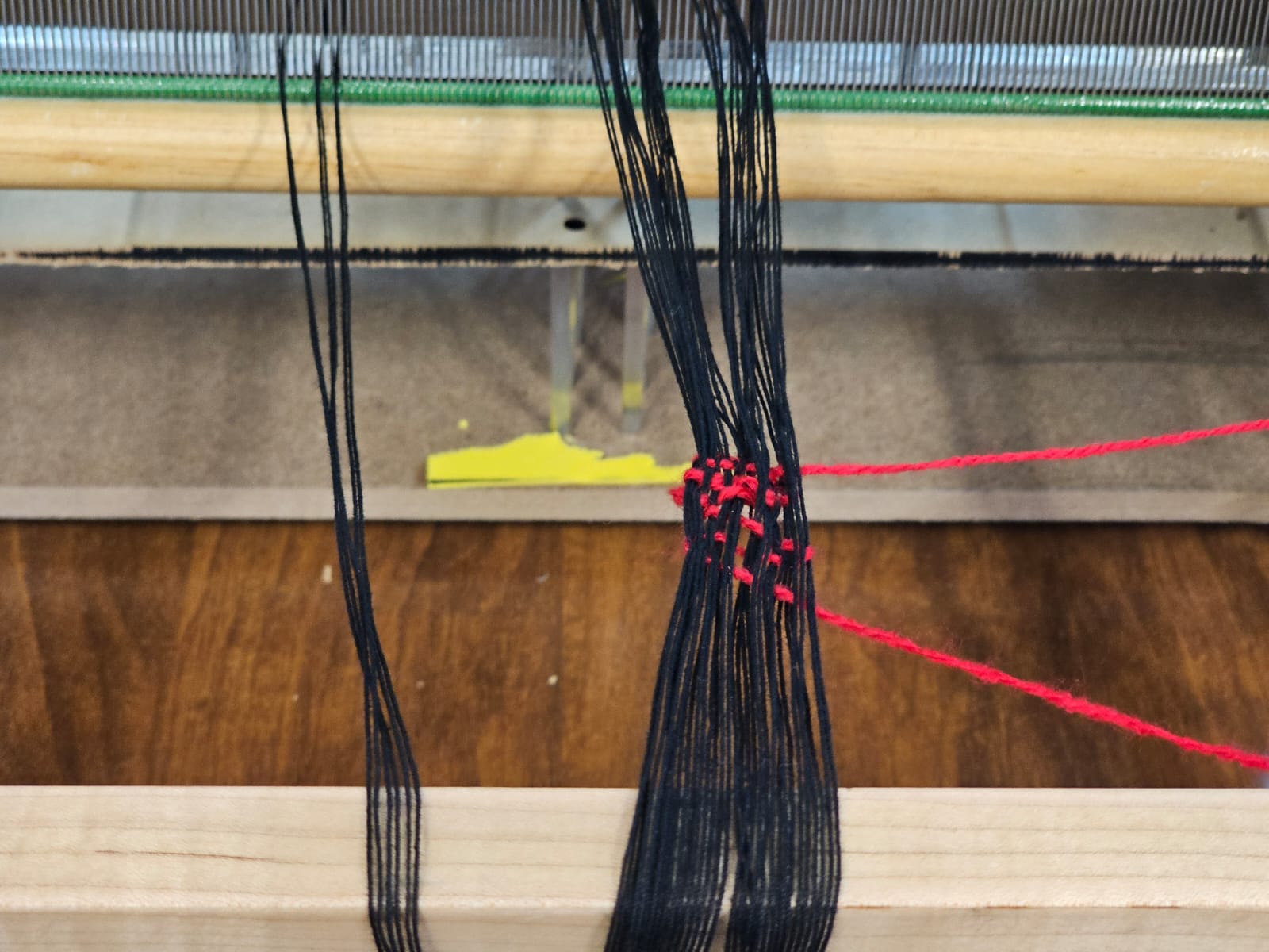
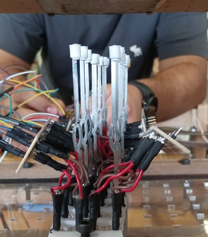
Heddles
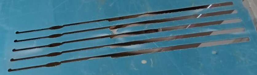
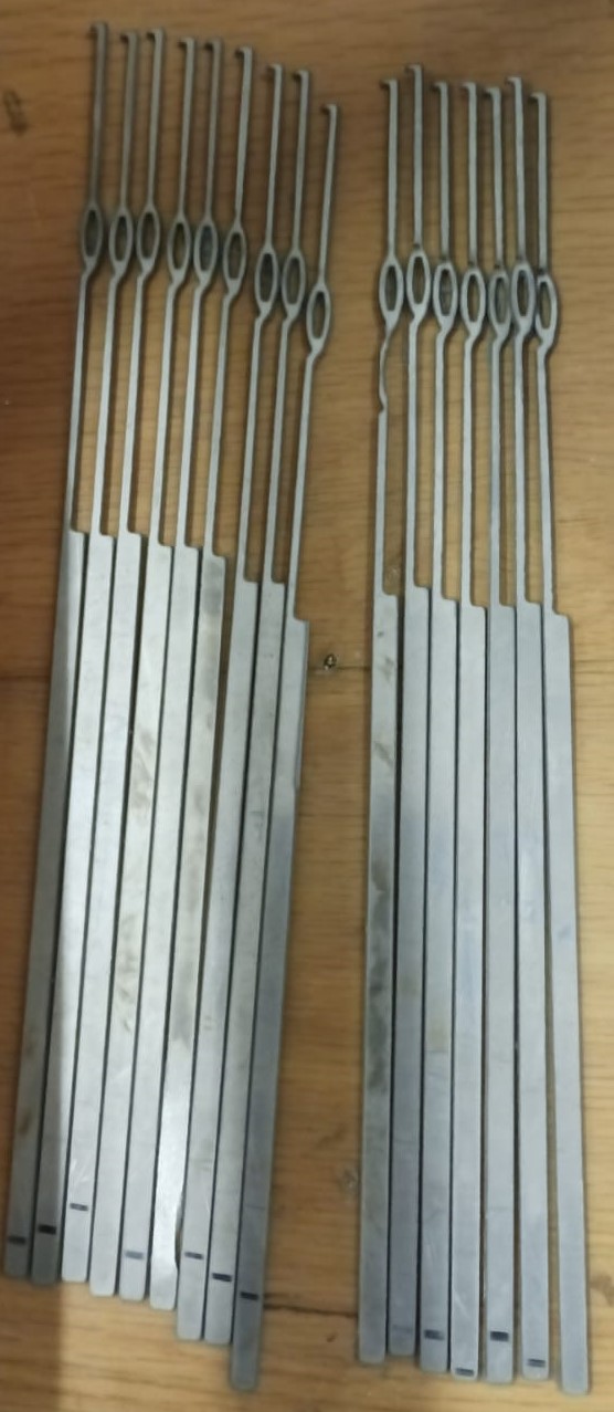
For the heddles, the typical loom heddles wouldn't work in this loom due to the mechanism. The heddles needed to have a small stop so they could be locked by the flip-disc mechanism, for this reason, the heddles were designed and cut in a water-jet.
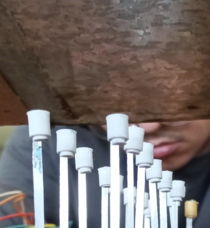
The last part of the heddles production is the design of small 3D-printed caps that will hold a magnet. As stated before to pick up the heddles the loom has a "drawer" with a metal sheet. By putting a magnet at the top of the heddle the magnet gets attached to the metal sheet and then it can be raised.
System Integration
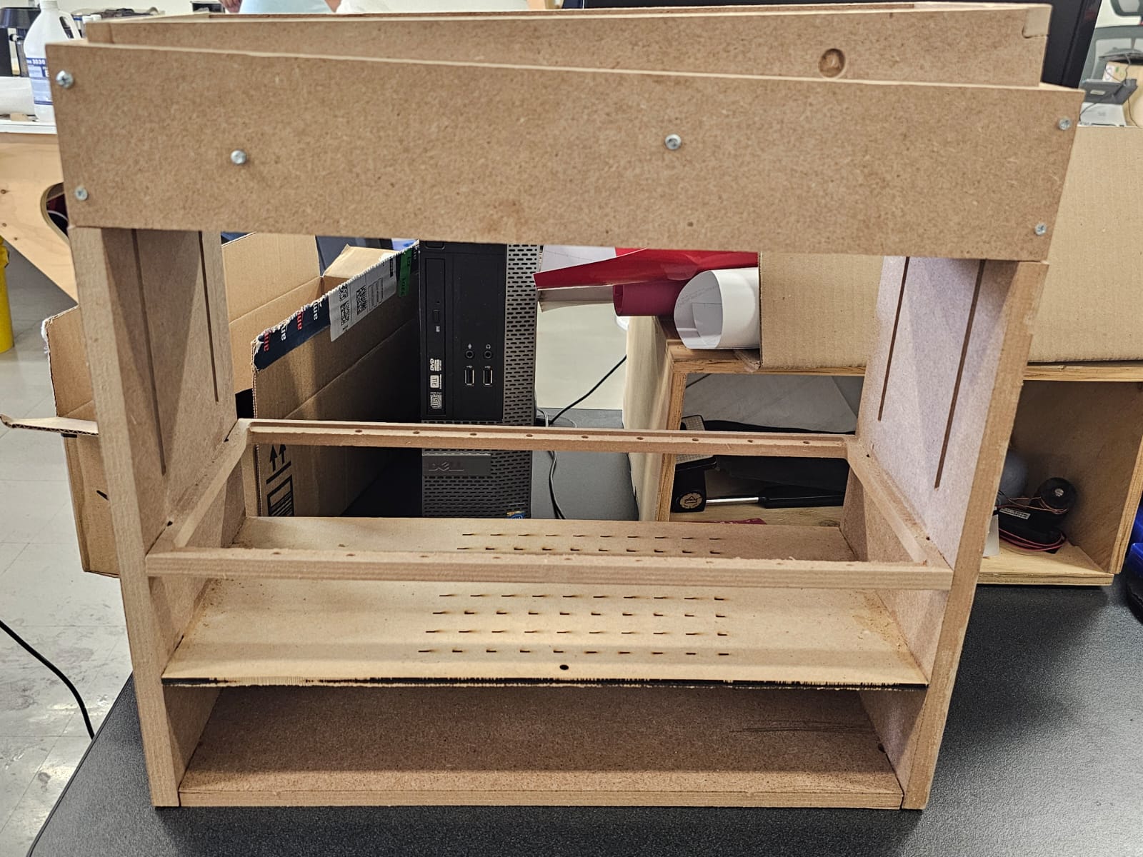
The first step was to assemble the structure of the loom, this consisted of the frame, the base of the loom, and the brush of the loom.
Once that was done it was time to install the mechanical component. And the heddles of the loom.
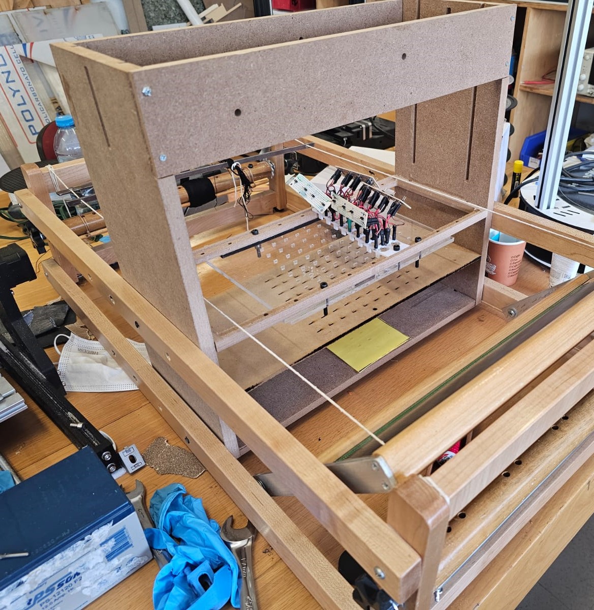
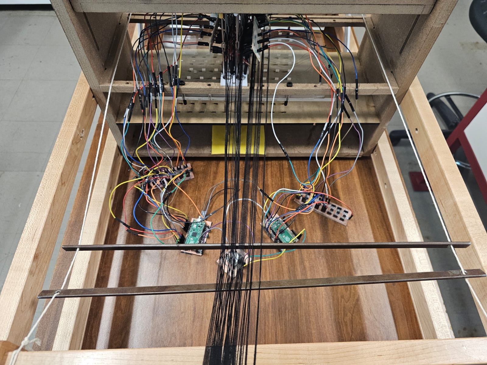
Finally, the last part was to add the electronics to the loom, this only consisted of connecting the PCB's to the cables of the coils.
Results