9. Output devices
This week's assignment was to add an output device to a microcontroller board I've designed, and program it to do something
Group assignment
This week's group assignment was to calculate the power consumption of an imput device. You can visit Ibero Puebla's web page to see more detailed information about measuring the power consumption of an output device.
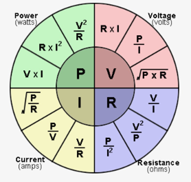
First, we need to understand the forces of electricity and the relationship between them.
- Power: The amount of energy used or transferred per unit of time.
- Voltage: Often likened to electrical pressure, voltage is the force that pushes electrical charges through a conductor (like a wire).
- Current: This is the flow of electrical charge carriers, usually electrons, through a conductor.
- Resistamce: Resistance opposes the flow of electrical current.
To understand the relationship between these forces we have this chart that can also be found on our group page.
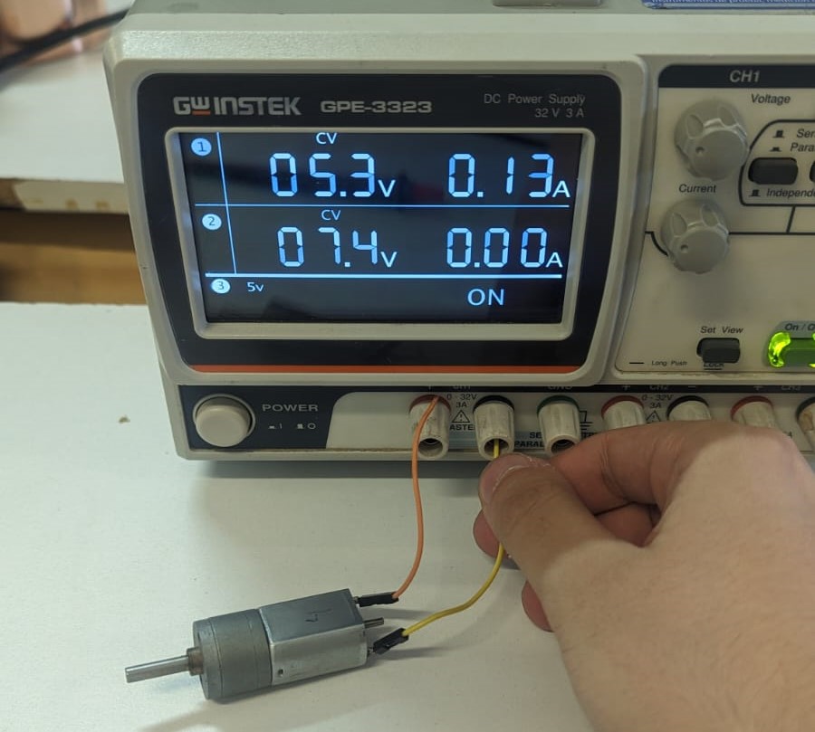
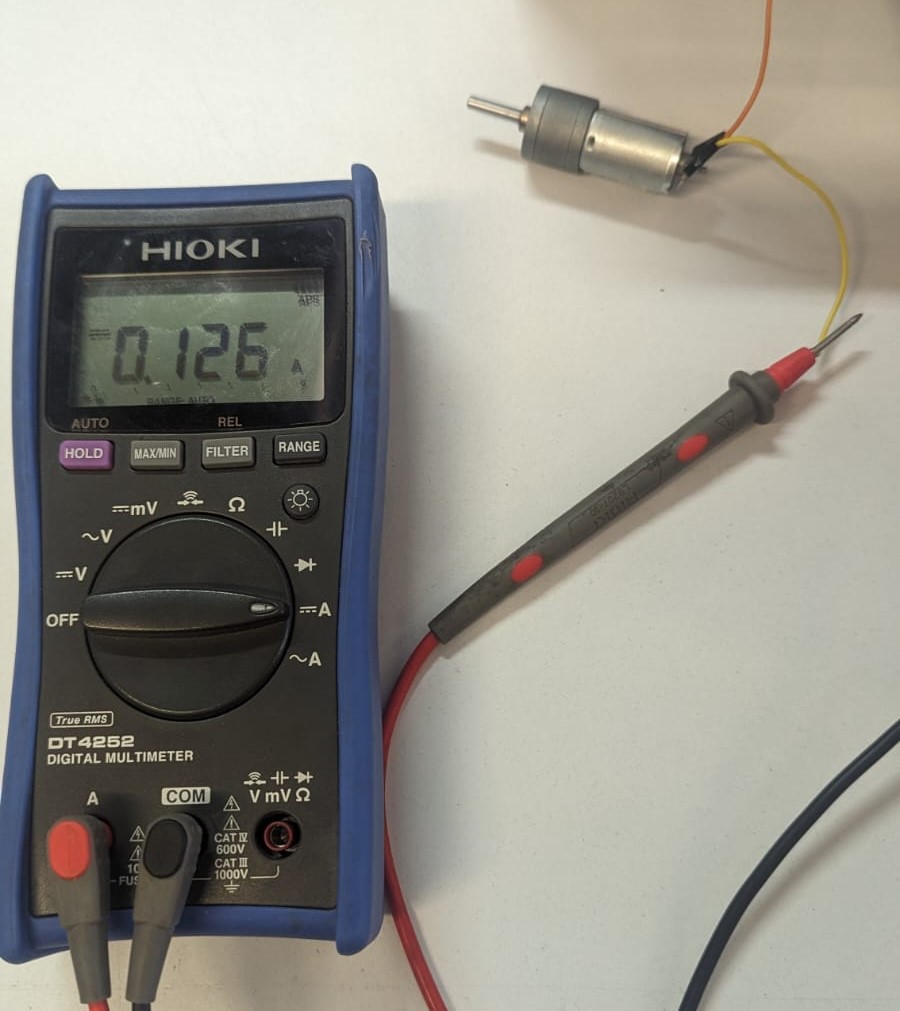
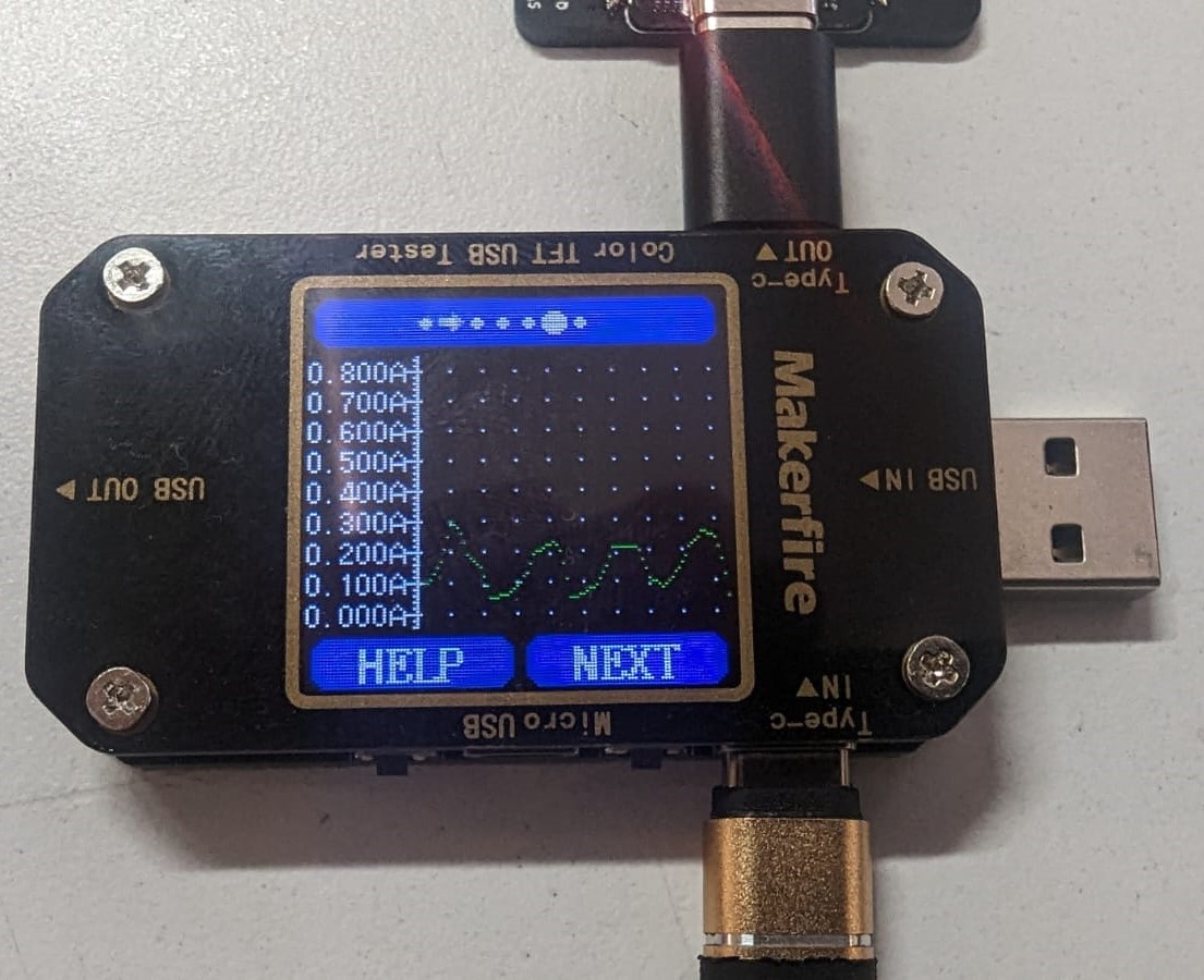
We used three different devices to measure the consumption of power of an output device.
- Using one of our DC power supplies which tells us how much current it's being used.
- Using our Hioki multimeter which we used on out last group assignment, on current measurement.
- Using a USB Current Voltage Checker.
How did I program the OLED screen?
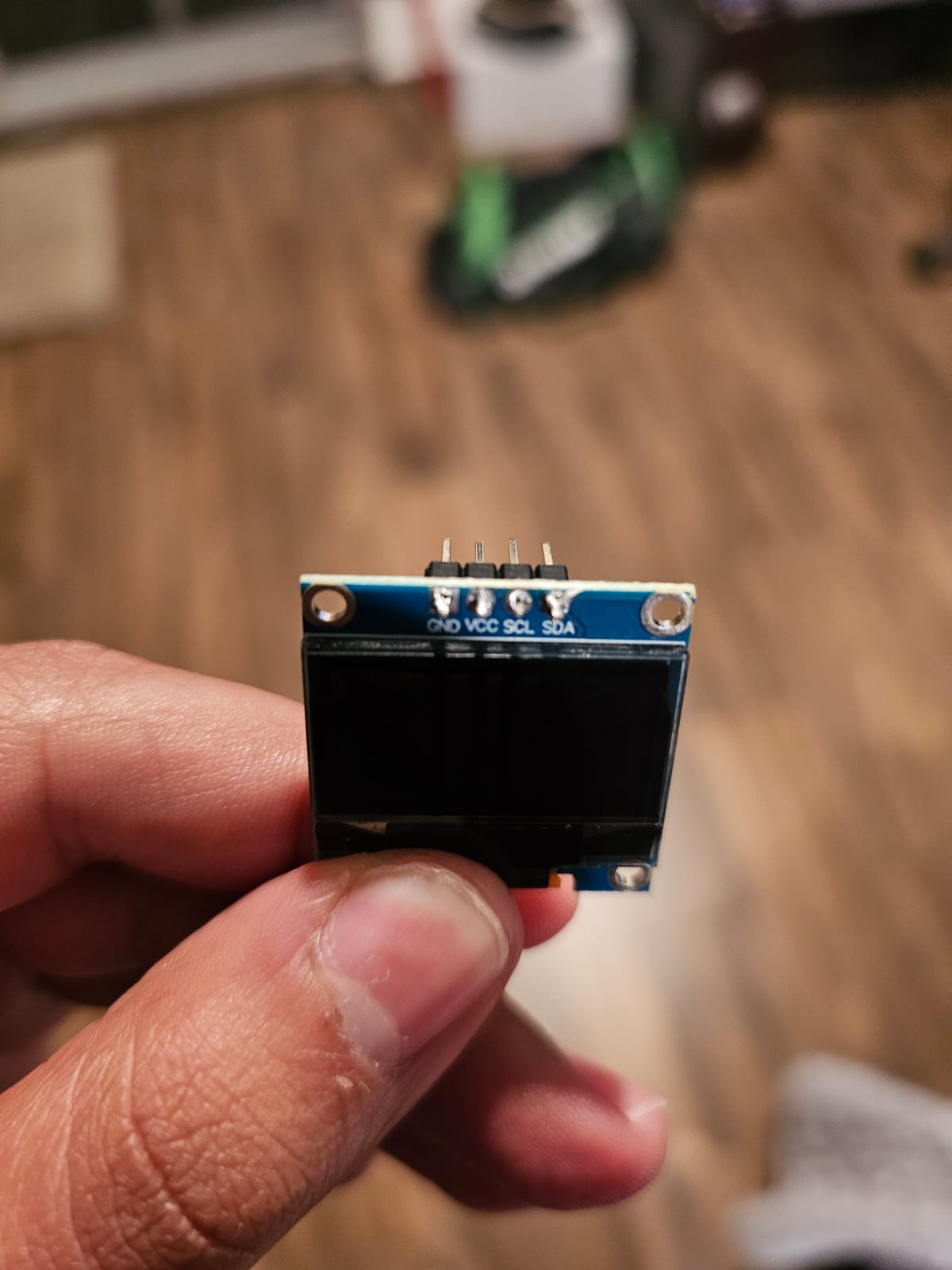
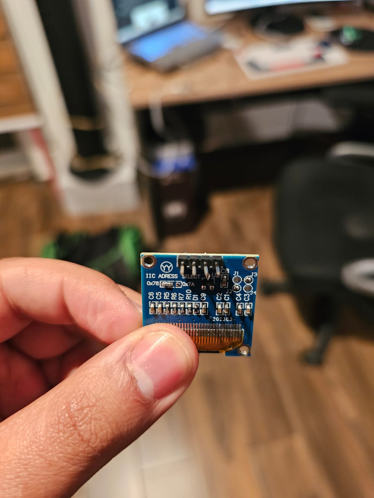
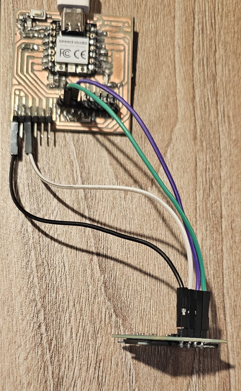
It was the first time I had ever programmed an OLED screen so it was an interesting learning process. The first thing I noticed was that it didn't have pins, I had to get some and soldered them to it.
I looked up tutorials in order to see how the OLED worked. The first thing I did was to make a simple program that printed on the screen "Helo world".This video by Nuevas Tecnologias JA helped me a lot. (its in spanish) Tutorial
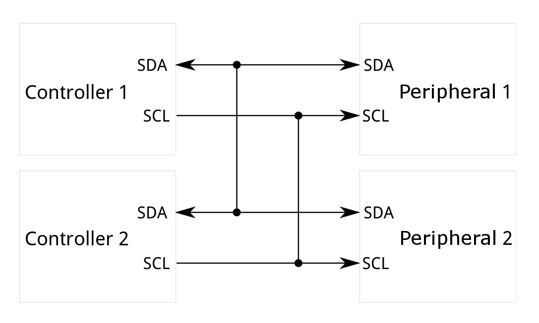
I encountered that the OLED screen uses an I2C connection. I2C, or Inter-Integrated Circuit, is a communication protocol commonly used to connect multiple integrated circuits on the same board. It uses two lines for communication: SDA (Serial Data) and SCL (Serial Clock).
- Controller (Primary): This device initiates communication and controls the clock line (SCL). It sends commands and data to the peripheral devices.
- Peripheral (Secondary): These devices respond to the controller. They can send data back when requested but do not initiate communication on their own.
In this case the controller would be my XIAO and the Peripheral would be the OLED screen.
How it Works
- Start Condition: The controller sends a start condition by pulling the SDA line low while SCL is high, signaling the beginning of a communication session.
- Addressing: The controller then sends the 7-bit address of the peripheral it wants to communicate with, followed by a read/write bit. This address allows multiple devices to share the same bus.
- Acknowledgment: The peripheral with the matching address responds by pulling the SDA line low (acknowledge bit).
- Data Transfer: Data is transferred between the controller and the peripheral. Each byte sent is followed by an acknowledgment from the receiver.
- Stop Condition: The controller ends the communication by releasing the SDA line while SCL is high, signaling the stop condition.
Heres a diagram of an I2C connection:
I did a first test where I displayed "Hello World" on the Oled screen.
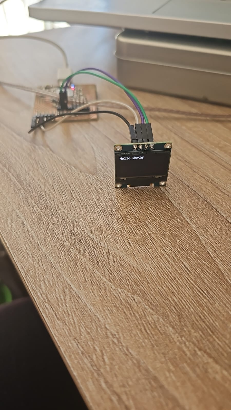
Code for "Hellow World" (Arduino)
Code "Hello World"
				#include  //This library allows communication with SPI devices with the Arduino as the controller.
				#include  //This library allows I2C communication
				#include  //Core graphic library for the OLED display
				#include  //Library for the specific size of the OLED screen

				#define SCREEN_WIDTH 128 // OLED display width, in pixels
				#define SCREEN_HEIGHT 64 // OLED display height, in pixels

				// Declaration for an SSD1306 display connected to I2C (SDA, SCL pins)
				// The pins for I2C are defined by the Wire-library.
				// On an arduino UNO:       A4(SDA), A5(SCL)
				// On an arduino MEGA 2560: 20(SDA), 21(SCL)
				// On an arduino LEONARDO:   2(SDA),  3(SCL), ...
				#define OLED_RESET     -1 // Reset pin # (or -1 if sharing Arduino reset pin)
				#define SCREEN_ADDRESS 0x3C // Identify the device's address in the I2C connection
				Adafruit_SSD1306 display(SCREEN_WIDTH, SCREEN_HEIGHT, &Wire, OLED_RESET);

				void setup() {
				display.begin(SSD1306_SWITCHCAPVCC, SCREEN_ADDRESS); // SSD1306_SWITCHCAPVCC = generate display voltage from 3.3V internally
				display.clearDisplay(); // Clear the buffer
				display.setTextSize(1); //Set the text size
				display.setTextColor(WHITE); //Set text color
				display.setCursor(0,0); //Set's ther cursor initial position
				display.print("Hello World");
				display.display(); // Show initial display buffer contents on the screen. The library initializes this with an Adafruit splash screen.

				}

				void loop() {
				// put your main code here, to run repeatedly:

				}
After learning how to add text to the OLED screen I decided to add an image next to the text. I had some trouble with this becuse there are diferent ways to add images, I also didn't now how to use the "map of the images so taht they would appear on the screen. Luckily I was able to find a tutorial, by Mision Critical, that helped me add images: Images tutorial
There I uploaded my image, adjusted its size, chose the background color, adjusted its brightness, scaled it to preserve its dimensions and converted the image to a cpp file.
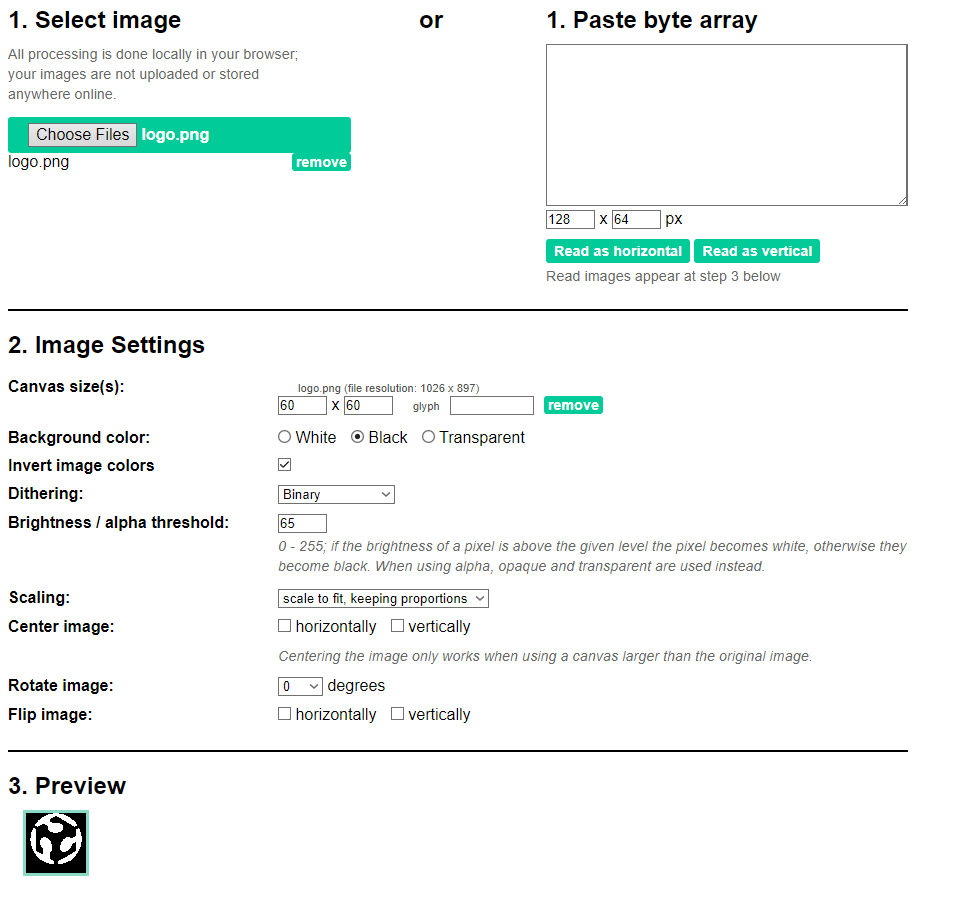
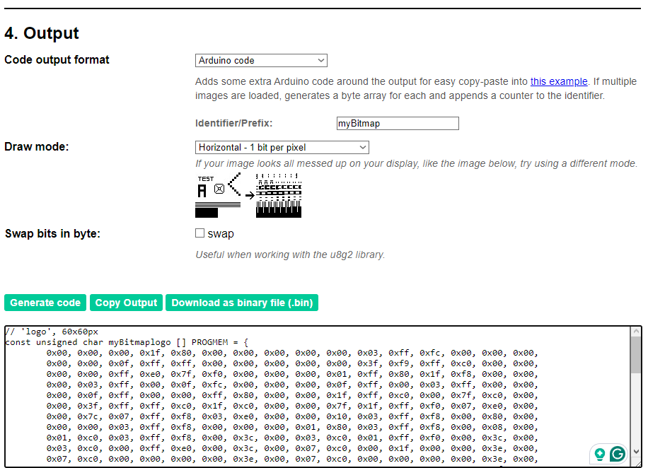
After that just copy the code from the image and add it to my final code.
Final code
Final Code
#include //This library allows communication with SPI devices with the Arduino as the controller.
#include //This library allows I2C communication
#include //Core graphic library for the OLED display
#include //Library for the specific size of the OLED screen
#define SCREEN_WIDTH 128 // OLED display width, in pixels
#define SCREEN_HEIGHT 64 // OLED display height, in pixels
// Declaration for an SSD1306 display connected to I2C (SDA, SCL pins)
// The pins for I2C are defined by the Wire-library.
// On an arduino UNO: A4(SDA), A5(SCL)
// On an arduino MEGA 2560: 20(SDA), 21(SCL)
// On an arduino LEONARDO: 2(SDA), 3(SCL), ...
#define OLED_RESET -1 // Reset pin # (or -1 if sharing Arduino reset pin)
#define SCREEN_ADDRESS 0x3C // Identify the device's address in the I2C connection
Adafruit_SSD1306 display(SCREEN_WIDTH, SCREEN_HEIGHT, &Wire, OLED_RESET);
// OLED Animation: aircraft
// Code auto-generated by https://wokwi.com/animator, graphics by icons8.com
// 'logo', 128x64px
const unsigned char myBitmaplogo [] PROGMEM = {
0x00, 0x00, 0x00, 0x7f, 0xe0, 0x00, 0x00, 0x00, 0x00, 0x00, 0x03, 0xff, 0xfc, 0x00, 0x00, 0x00,
0x00, 0x00, 0x0f, 0xff, 0xff, 0x00, 0x00, 0x00, 0x00, 0x00, 0x3f, 0xf9, 0xff, 0xc0, 0x00, 0x00,
0x00, 0x00, 0xff, 0xe0, 0x7f, 0xf0, 0x00, 0x00, 0x00, 0x01, 0xff, 0xc0, 0x3f, 0xf8, 0x00, 0x00,
0x00, 0x07, 0xff, 0x00, 0x0f, 0xfe, 0x00, 0x00, 0x00, 0x0f, 0xff, 0x00, 0x07, 0xff, 0x00, 0x00,
0x00, 0x1f, 0xff, 0x00, 0x01, 0xff, 0x80, 0x00, 0x00, 0x3f, 0xff, 0xce, 0x00, 0x7f, 0xc0, 0x00,
0x00, 0x3f, 0xff, 0xff, 0xc0, 0x1f, 0xc0, 0x00, 0x00, 0x7f, 0x1f, 0xff, 0xf8, 0x0f, 0xe0, 0x00,
0x00, 0x7c, 0x07, 0xff, 0xf8, 0x01, 0xe0, 0x00, 0x00, 0x10, 0x03, 0xff, 0xf8, 0x00, 0x80, 0x00,
0x00, 0x00, 0x03, 0xff, 0xf8, 0x00, 0x00, 0x00, 0x01, 0x80, 0x03, 0xff, 0xf8, 0x00, 0x18, 0x00,
0x03, 0xc0, 0x03, 0xff, 0xf8, 0x00, 0x3c, 0x00, 0x03, 0xc0, 0x01, 0xff, 0xf8, 0x00, 0x3c, 0x00,
0x03, 0xc0, 0x00, 0xff, 0xe0, 0x00, 0x3e, 0x00, 0x07, 0xc0, 0x00, 0x3f, 0x80, 0x00, 0x3e, 0x00,
0x07, 0xc0, 0x00, 0x00, 0x00, 0x00, 0x3e, 0x00, 0x07, 0xc0, 0x00, 0x00, 0x00, 0x00, 0x3e, 0x00,
0x0f, 0xc0, 0x00, 0x00, 0x00, 0x00, 0x3f, 0x00, 0x0f, 0xc0, 0x00, 0x00, 0x00, 0x00, 0xff, 0x00,
0x0f, 0xc0, 0xf8, 0x00, 0x00, 0xf9, 0xff, 0x00, 0x0f, 0xc1, 0xfc, 0x00, 0x03, 0xff, 0xff, 0x00,
0x0f, 0xc3, 0xfe, 0x00, 0x07, 0xff, 0xff, 0x00, 0x0f, 0xc3, 0xff, 0x00, 0x0f, 0xff, 0xff, 0x00,
0x0f, 0xc3, 0xff, 0x80, 0x1f, 0xff, 0xff, 0x00, 0x0f, 0xc3, 0xff, 0x80, 0x1f, 0xff, 0xff, 0x00,
0x07, 0xc3, 0xff, 0xc0, 0x1f, 0xff, 0x3e, 0x00, 0x07, 0xc3, 0xff, 0xc0, 0x1f, 0xfc, 0x3e, 0x00,
0x07, 0xc1, 0xff, 0xc0, 0x3f, 0xfc, 0x3e, 0x00, 0x07, 0xc1, 0xff, 0xc0, 0x3f, 0xf8, 0x3e, 0x00,
0x03, 0xc0, 0xff, 0xc0, 0x3f, 0xf8, 0x3c, 0x00, 0x03, 0xc0, 0xff, 0xc0, 0x3f, 0xf0, 0x3c, 0x00,
0x01, 0xc0, 0x7f, 0xc0, 0x3f, 0xe0, 0x38, 0x00, 0x01, 0xc0, 0x7f, 0xc0, 0x1f, 0x80, 0x38, 0x00,
0x00, 0xf0, 0x7f, 0x80, 0x0f, 0x00, 0xf0, 0x00, 0x00, 0xf8, 0x7f, 0x00, 0x00, 0x01, 0xf0, 0x00,
0x00, 0x7c, 0x7f, 0x00, 0x00, 0x03, 0xe0, 0x00, 0x00, 0x3f, 0xff, 0x00, 0x00, 0x0f, 0xc0, 0x00,
0x00, 0x1f, 0xff, 0x00, 0x00, 0x3f, 0xc0, 0x00, 0x00, 0x1f, 0xff, 0x00, 0x00, 0xff, 0x80, 0x00,
0x00, 0x0f, 0xff, 0x00, 0x01, 0xff, 0x80, 0x00, 0x00, 0x07, 0xff, 0x00, 0x0f, 0xff, 0x00, 0x00,
0x00, 0x03, 0xff, 0xc0, 0x1f, 0xfc, 0x00, 0x00, 0x00, 0x00, 0xff, 0xe0, 0x7f, 0xf0, 0x00, 0x00,
0x00, 0x00, 0x3f, 0xf8, 0xff, 0xc0, 0x00, 0x00, 0x00, 0x00, 0x0f, 0xf8, 0xff, 0x00, 0x00, 0x00,
0x00, 0x00, 0x03, 0xf8, 0xfc, 0x00, 0x00, 0x00, 0x00, 0x00, 0x00, 0x38, 0xc0, 0x00, 0x00, 0x00,
0x00, 0x00, 0x00, 0x00, 0x00, 0x00, 0x00, 0x00, 0x00, 0x00, 0x00, 0x00, 0x00, 0x00, 0x00, 0x00,
0x00, 0x00, 0x00, 0x00, 0x00, 0x00, 0x00, 0x00, 0x00, 0x00, 0x00, 0x00, 0x00, 0x00, 0x00, 0x00,
0x00, 0x00, 0x00, 0x00, 0x00, 0x00, 0x00, 0x00, 0x00, 0x00, 0x00, 0x00, 0x00, 0x00, 0x00, 0x00,
0x00, 0x00, 0x00, 0x00, 0x00, 0x00, 0x00, 0x00, 0x00, 0x00, 0x00, 0x00, 0x00, 0x00, 0x00, 0x00
};
// Array of all bitmaps for convenience. (Total bytes used to store images in PROGMEM = 1040)
const int myBitmapallArray_LEN = 1;
const unsigned char* myBitmapallArray[1] = {
myBitmaplogo
};
void setup() {
display.begin(SSD1306_SWITCHCAPVCC, SCREEN_ADDRESS);
display.clearDisplay();
display.setTextSize(1); //Set the text size
display.setTextColor(WHITE); //Set text color
display.setCursor(60,10); //Set's ther cursor initial position
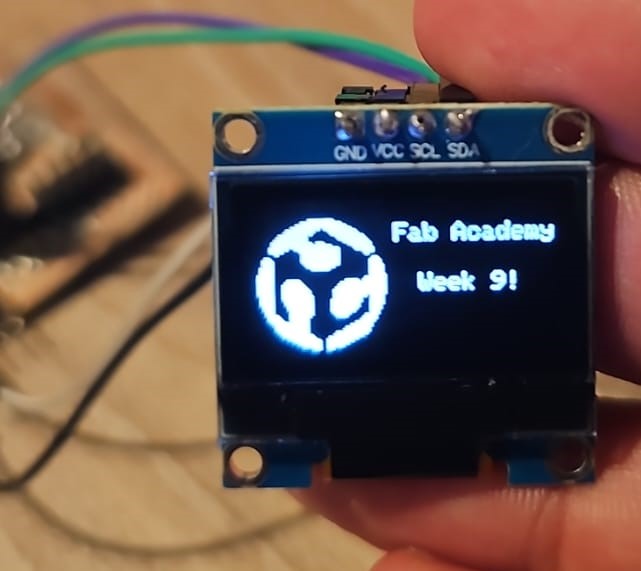
display.print("Fab Academy");
display.setCursor(70,30); //Set's ther cursor initial position
display.print("Week 9!");
delay(2000);
}
void loop() {
display.drawBitmap(0,8,myBitmaplogo,60,60,WHITE);
display.display();
}
Final Result