WEEK 7 - Computer-Controlled Machining
Make (design+mill+assemble) something big
Thinking about what I was going to do was a complicated procedure, I had so many ideas but none of them convinced me at all.
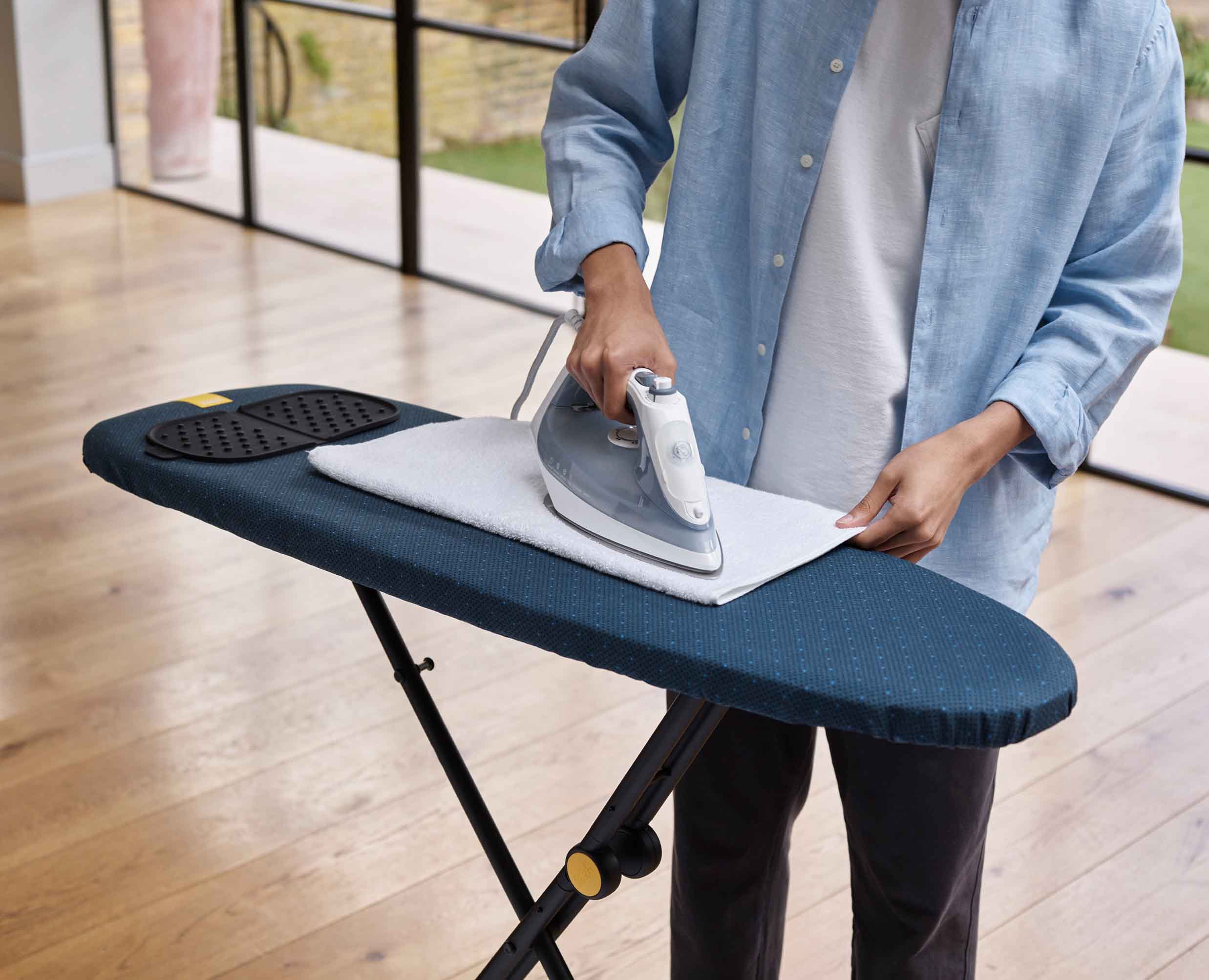
Then I remembered that I am a foreigner and that my house only has a table and a bed, so I decided that I would make a piece of furniture for my house, but then I remembered that I needed to iron a shirt for a class and I didn't have an ironing board.
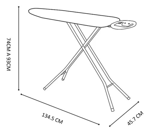
So I decided that in my week 7, I would make an ironing donkey, and that was my approach, so on the internet I decided to look for a plan with the main measurements of it. The following image was the one I based it on.
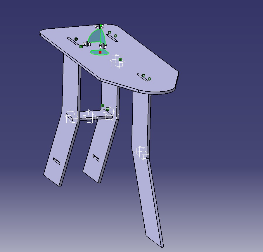
I decided to design my ironing board in CATIA, I did it with the module called CATPART, in which I made the legs, the support that goes in the middle of the legs, and finally the main part, the surface where you put the clothes to pass the iron.
This is the image of the same assembly, but with an "explosion", so that each of the designed pieces can be better appreciated.
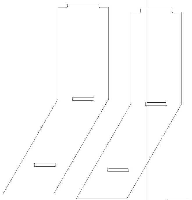
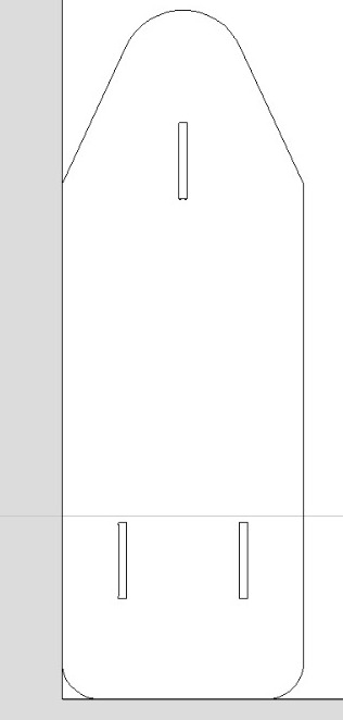
After having already made the design, observing that each of the pieces fit perfectly, we had to make a DXF drawing for the cutting of each of the pieces.
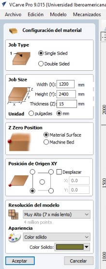
And then, I used the program called V CARVE
This program was very useful, because it is the program to make the cuts in the CNC ROUTER, in this program you can select what kind of work to do according to the DXF you have in hand, such as making cuts along the perimeter of a figure, or devastar all a selected area.
And opening the program, the first thing you have to do is to set up your worksheet, putting the correct measurements of your 15 mm MDF board.
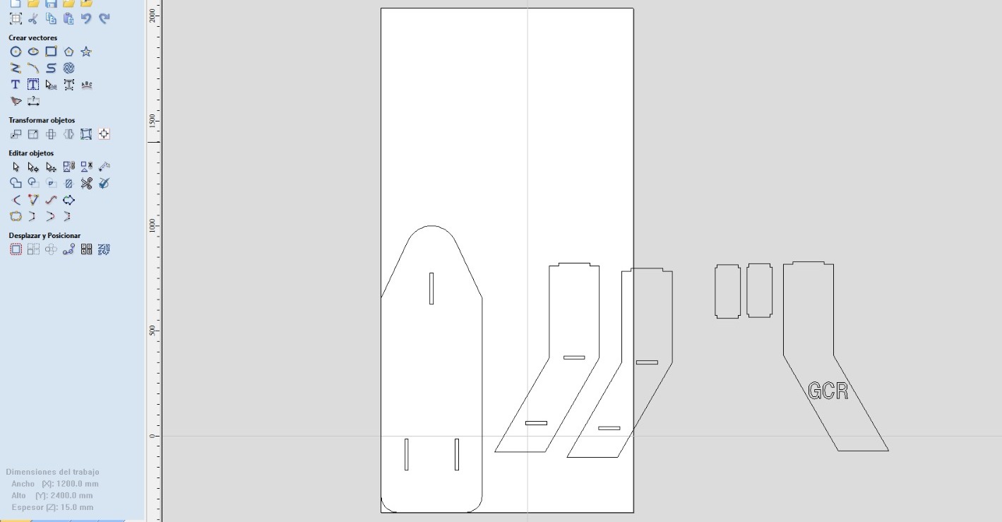
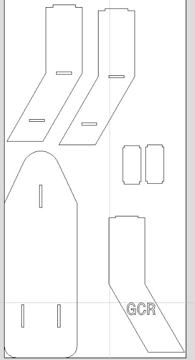
Then you open the dxf file in the program, you will have to place the file in the working plane you made before.
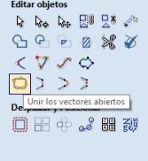
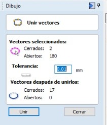
The next step is to join all the vectors, this serves to not have any vector alone, makes a figure is one, and not several, this serves to make the route of the cnc router more efficient.
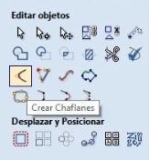
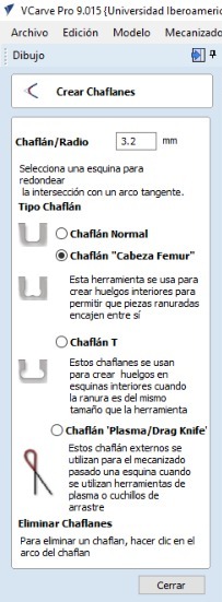
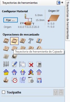
After having done this step, the next step is to create the chamfers, the option to be chosen is the “femur head” that assimilates a bone, this option is chosen to make it much easier to insert previously cut pieces.
After having done this step, the next step is to create the chamfers, the option to be chosen is the “femur head” that assimilates a bone, this option is chosen to make it much easier to insert previously cut pieces.
After having done this step, the next step is to create the chamfers, the option to be chosen is the “femur head” that assimilates a bone, this option is chosen to make it much easier to insert previously cut pieces.
After having done this step, the next step is to create the chamfers, the option to be chosen is the “femur head” that assimilates a bone, this option is chosen to make it much easier to insert previously cut pieces.
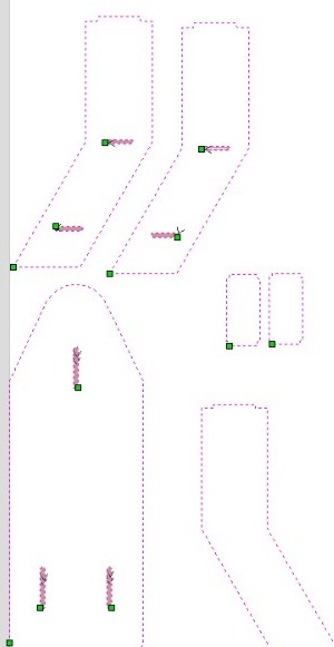
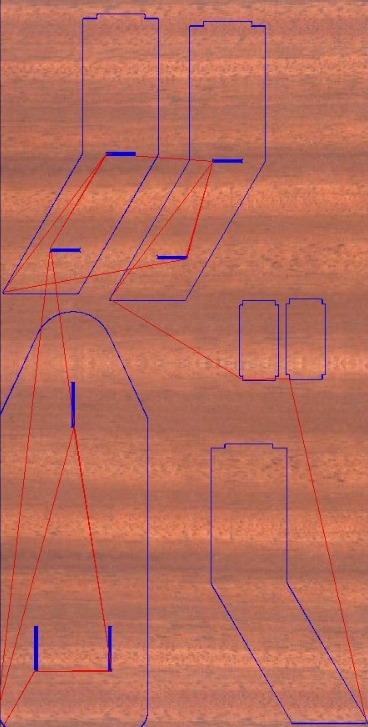
Now follows the part of the “tool paths”, where we will practically configure which parts of our strokes will be cut, whether the perimeter or the area of the delimited figure..
Now follows the part of the “tool paths”, where we will practically configure which parts of our strokes will be cut, whether the perimeter or the area of the bounded slot.
Now follows the part of the “tool paths”, where we will practically configure which parts of our strokes will be cut, whether the perimeter or the area of the bounded slot.
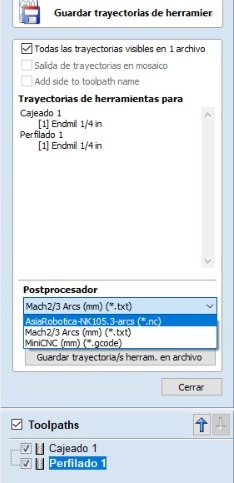
And the last step in the Vcarve software, is to export it to the CNC router to be used, in this case the ASIAROBOTIC.
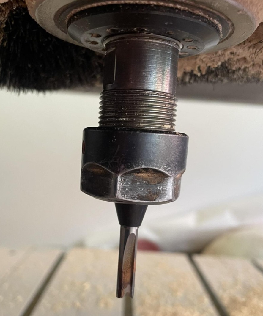
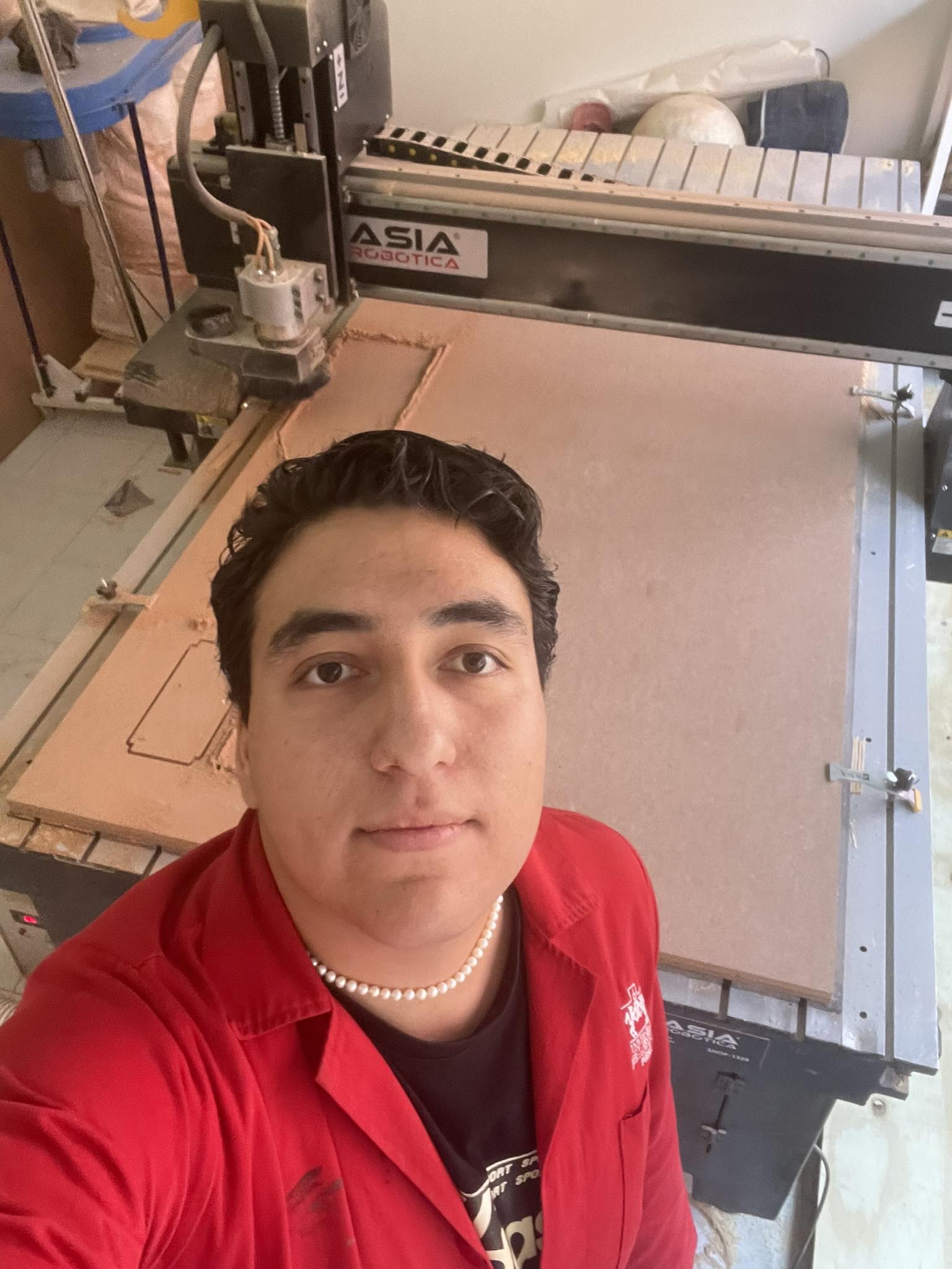
Then we move on to what involves more physical work, which is to put the "LIENZO", which would be the 15 mm mdf in the CNC ROUTER. Where we have to prepare the tool to work properly, you can see the photos of how was the installation of such tools.
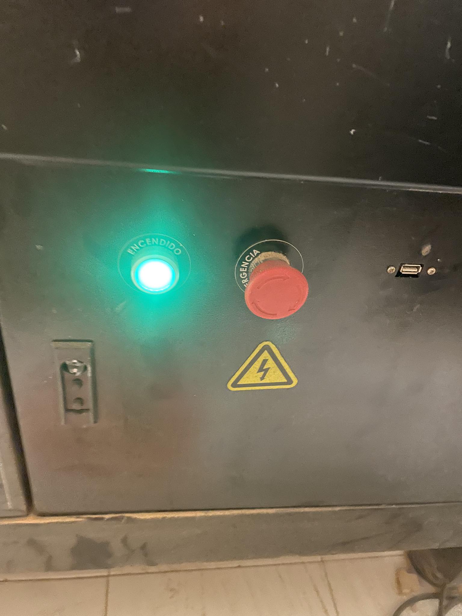
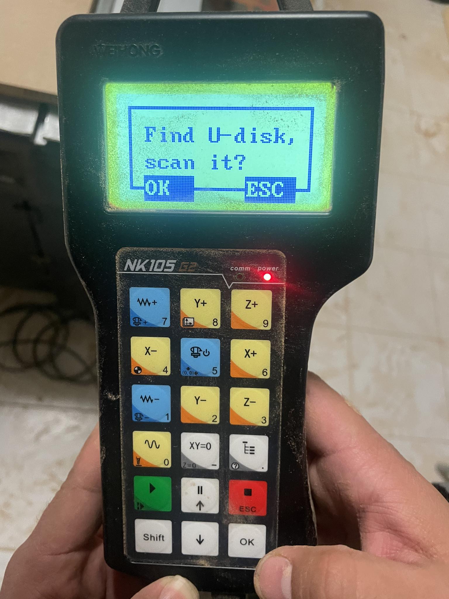
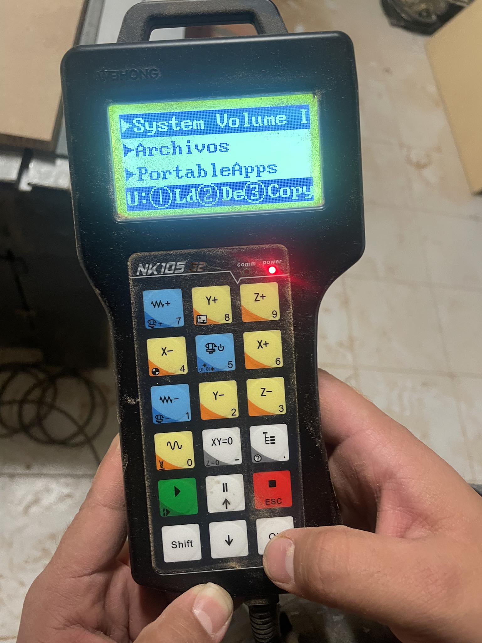
Now what we will do is to adjust the machine to start making the corresponding cuts, where the whole process to make the machine work will be shown, from turning it on, inserting the USB memory stick, to the following steps
After inserting it, the machine will indicate that there is a usb memory to which you can access, where you will find all the files that the machine can read.
it scrolls you in the menu, where you have to select the options, you have to enter the USB memory, from there, copy the file that you are going to cut, from there, enter the storage of the machine, the internal storage, and that is where you have to paste the previously selected file.
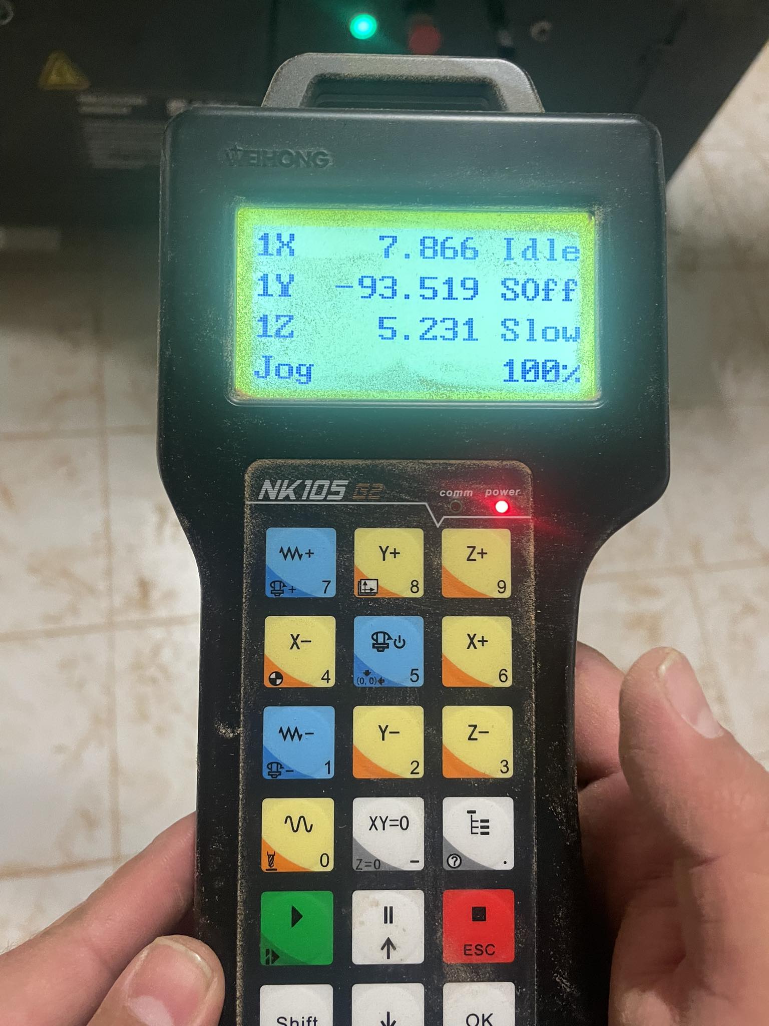
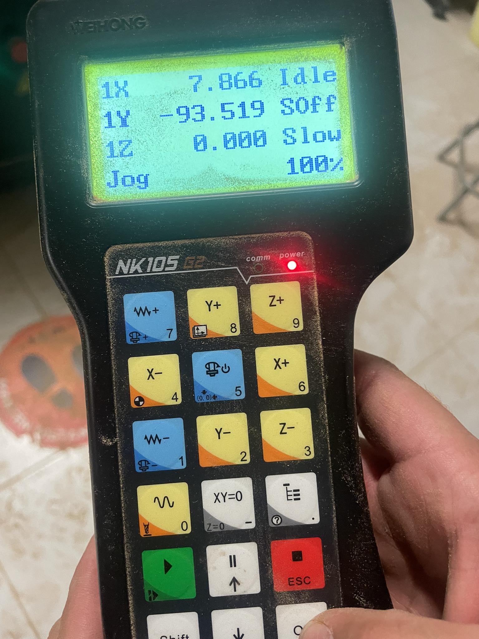
Then you have to place the Z axis at 0, I show 2 photos of how it was before, and how it is after, the z axis is placed just at the top of the material, where it does not fit even the thickness of a blank sheet.
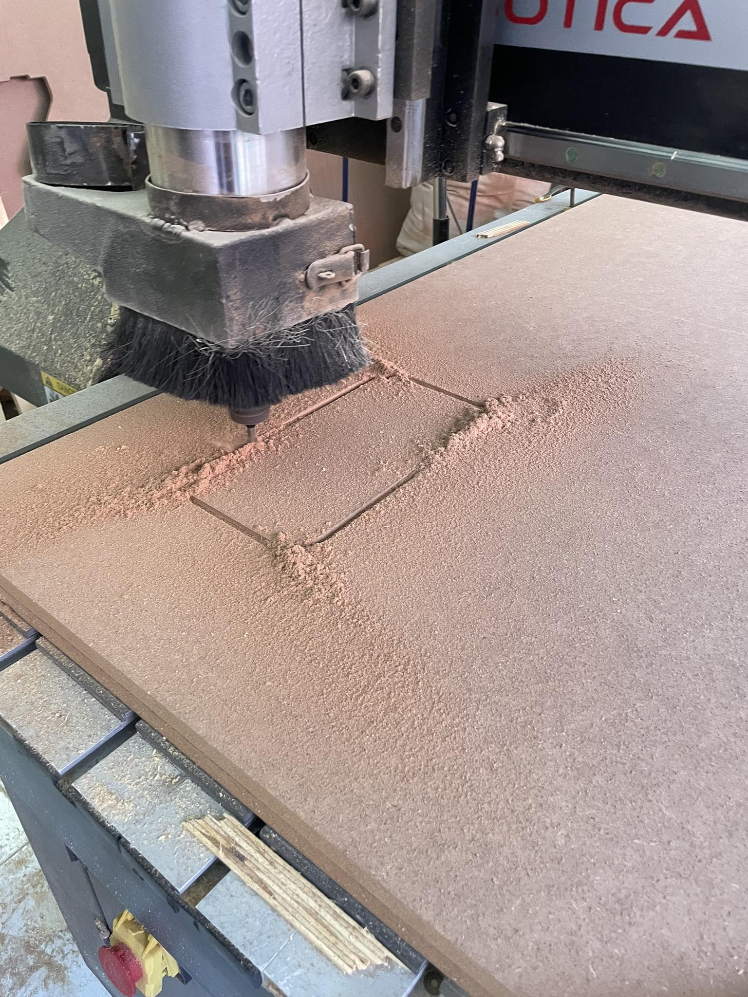
Then press the green button and the MAGIC BEGINS.
this is me holding the tube that sucks up all the dust that the machine makes when making the cuts
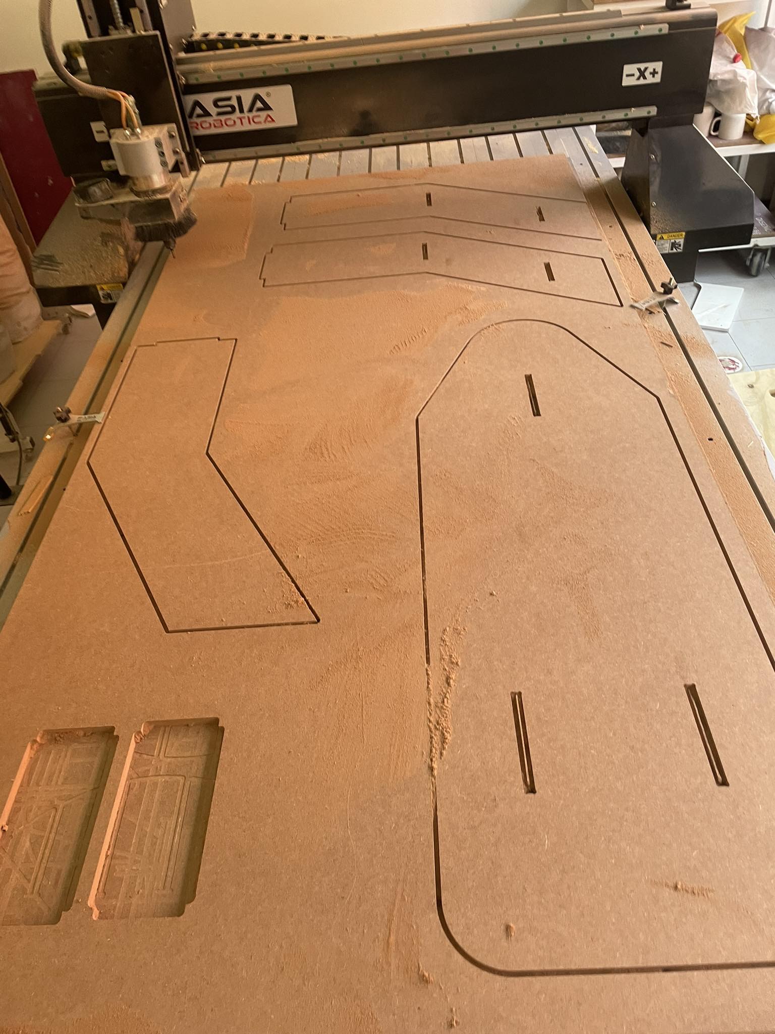
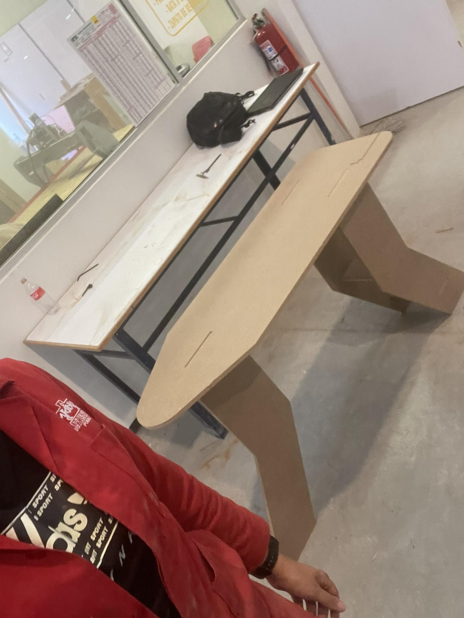
This is the MDF, after all the cuts made, this is how the template looks like.
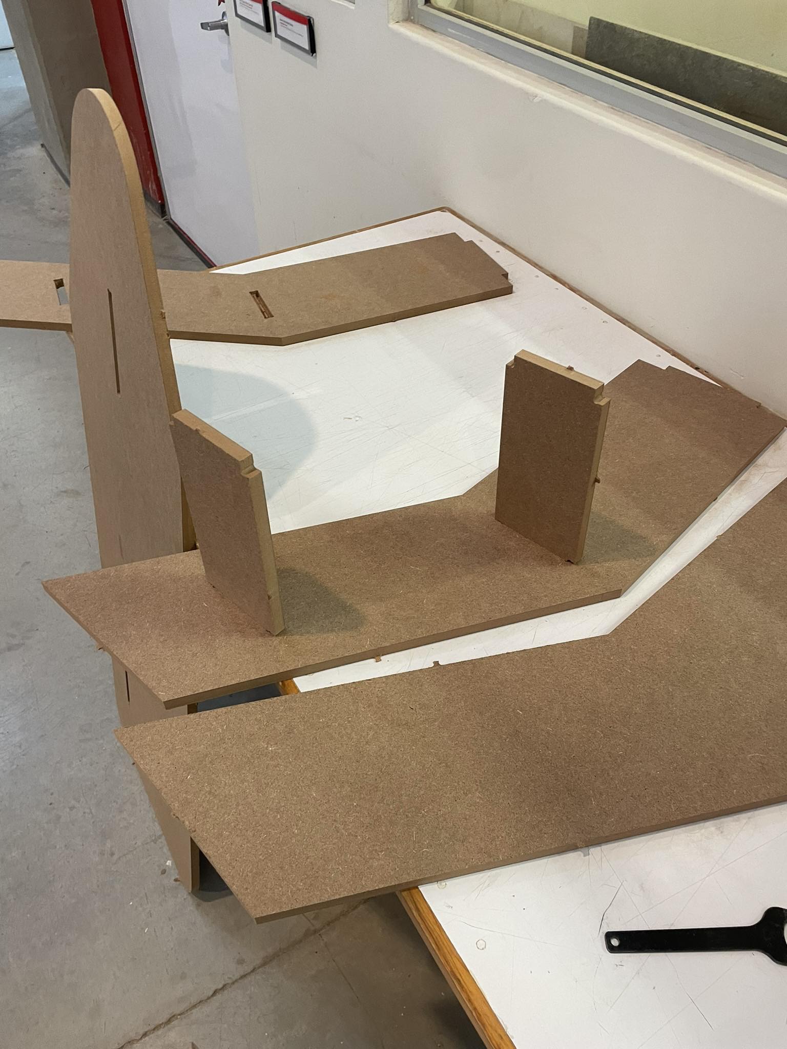
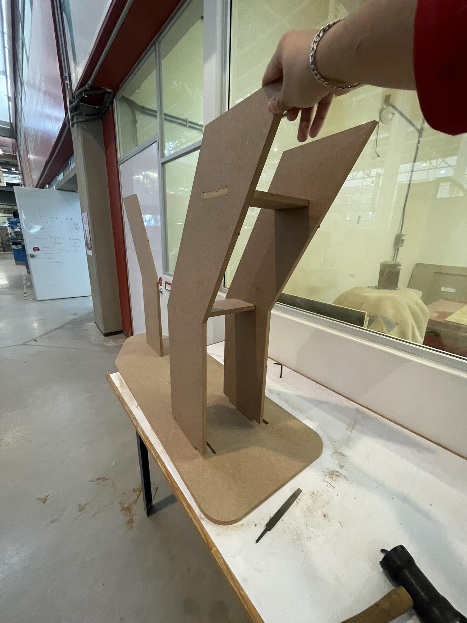
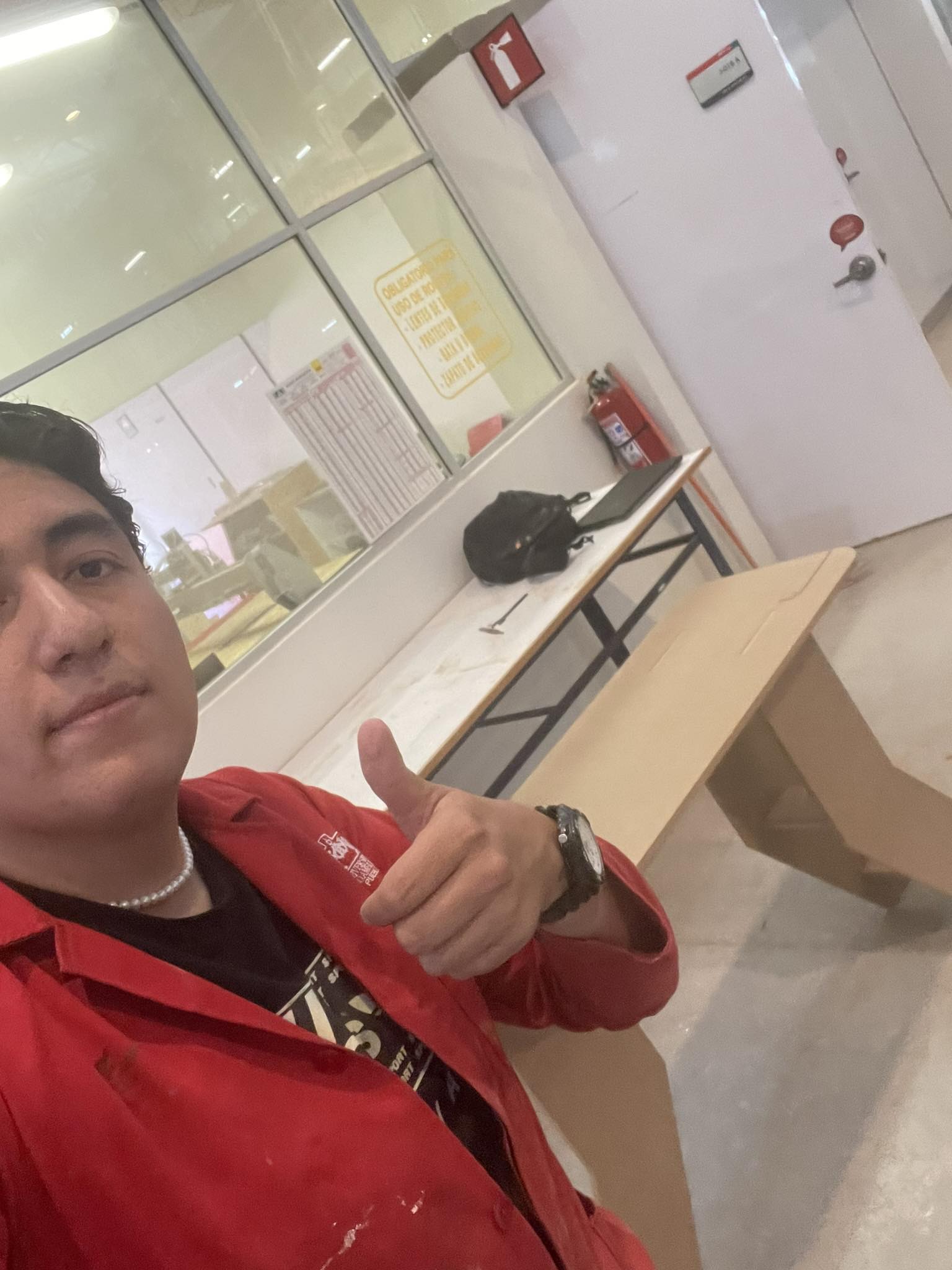
This is the process in which I put together my final structure, all the pictures show a part of this laborious process.
FINAL RESULT
- © Untitled. All rights reserved.
- Design by : Gianfranco Carrasco Rubio