WEEK 4 - ELECTRONICS PRODUCTIONS
Make and test a microcontroller development board
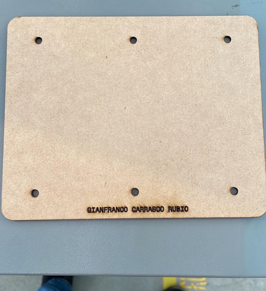
The first action we took this week was to cut our "sacrificial board", this was to put the copper plate on top so that when the tool drills, it does not do any damage to the machine.
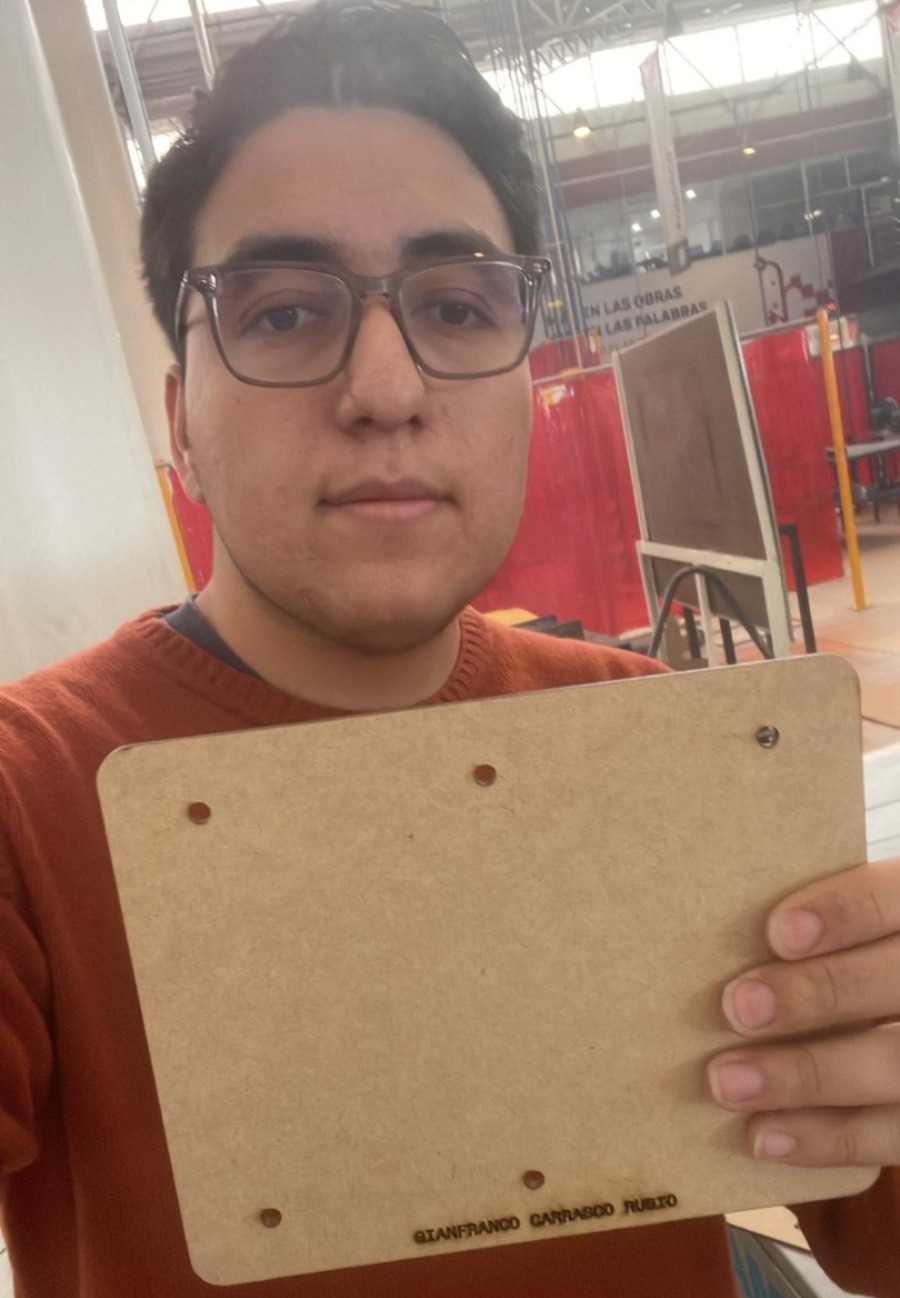
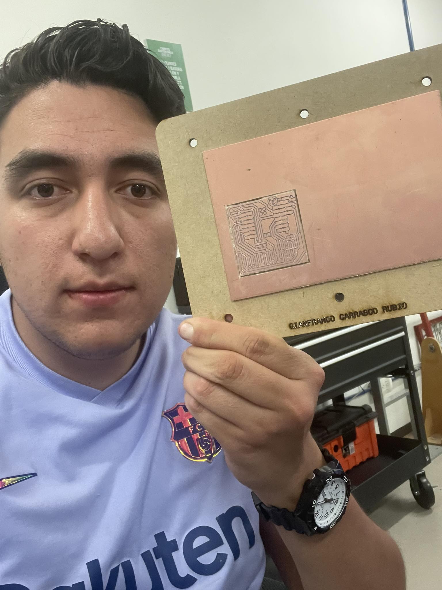
Me with my sacrifical board
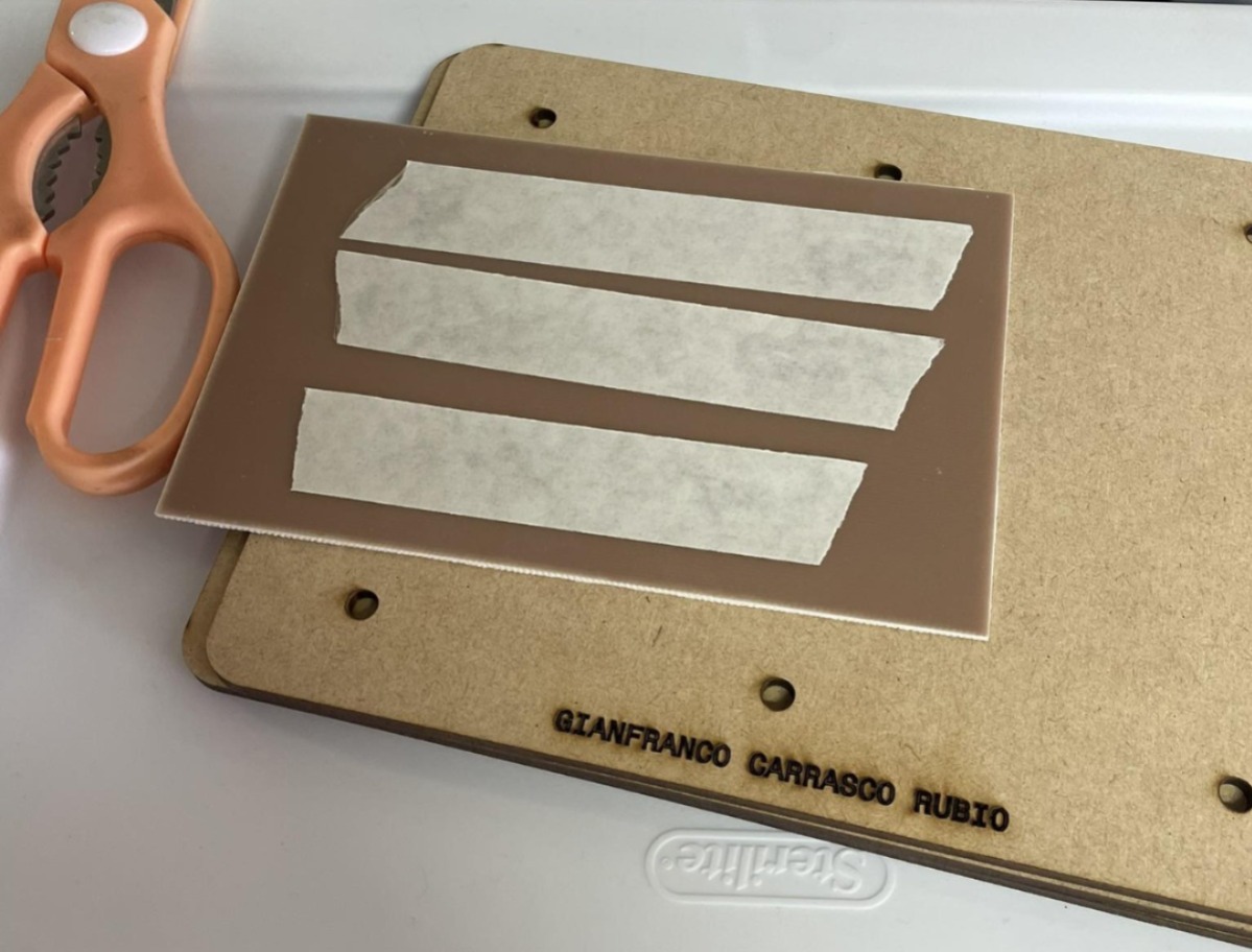
Then I put double-sided tape on the copper plate, the reason for this is so that when the tool is activated, it does not move and does not damage the work done, since each of the guides are super necessary and all have an essential function.
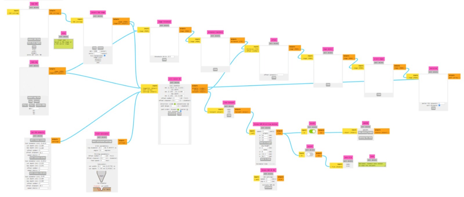
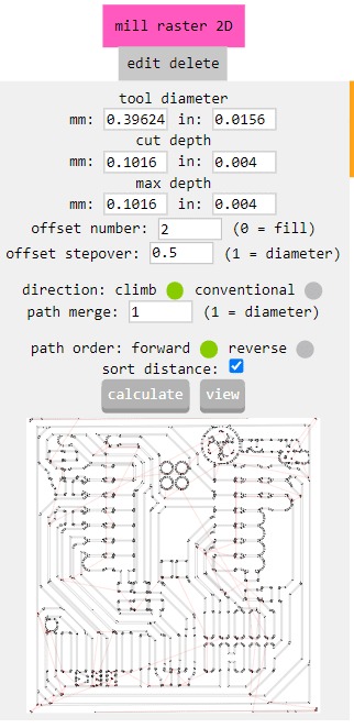
When we choose the "mill 2D PCB" option, a menu appears that might seem daunting initially. However, we only need to upload our image in .png format, provide the program with the parameters of our cutting tool, and adjust other settings such as the number of passes. The first menu that appears is shown in the following image.
After making the corresponding configurations, such as the tool diameter (which I will show later), the cutting depth and the max depth, the same page will give us the file to be able to use the machine.
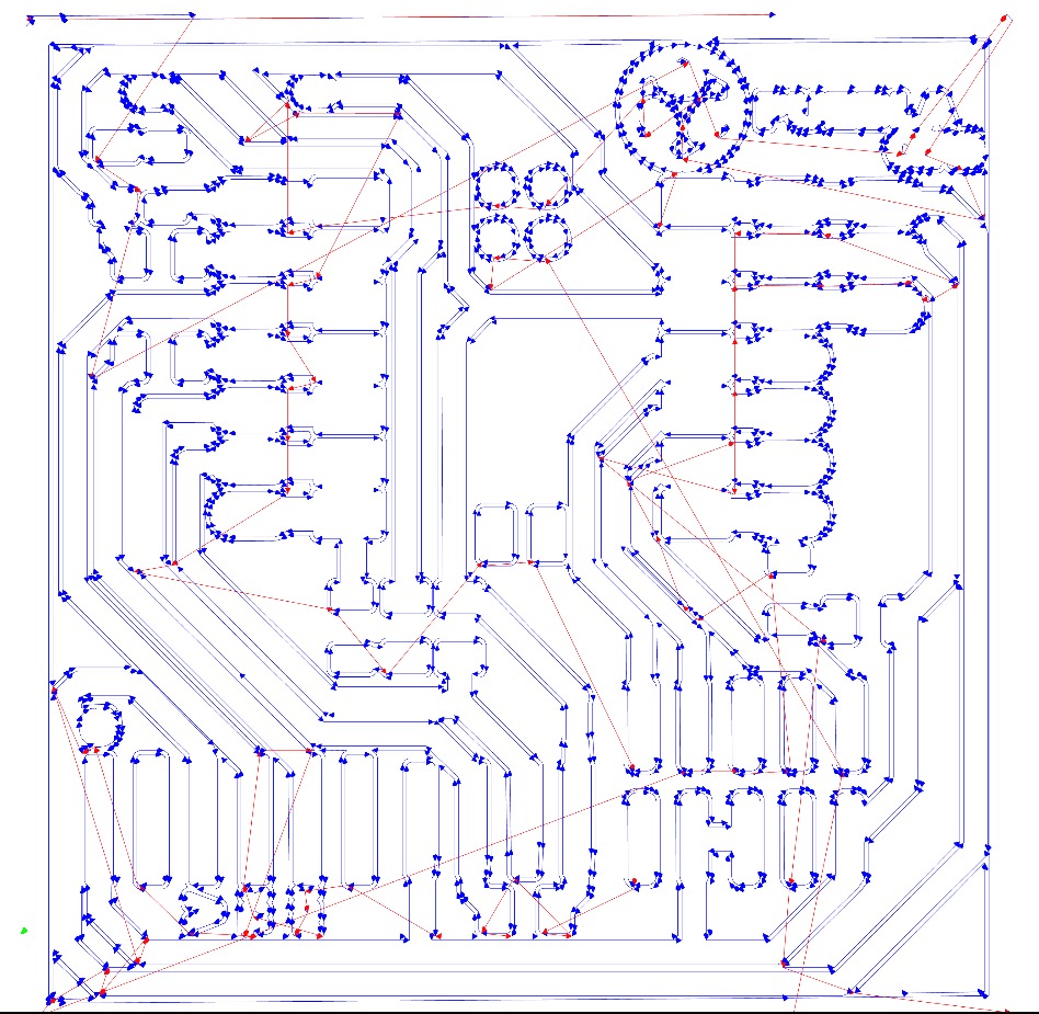
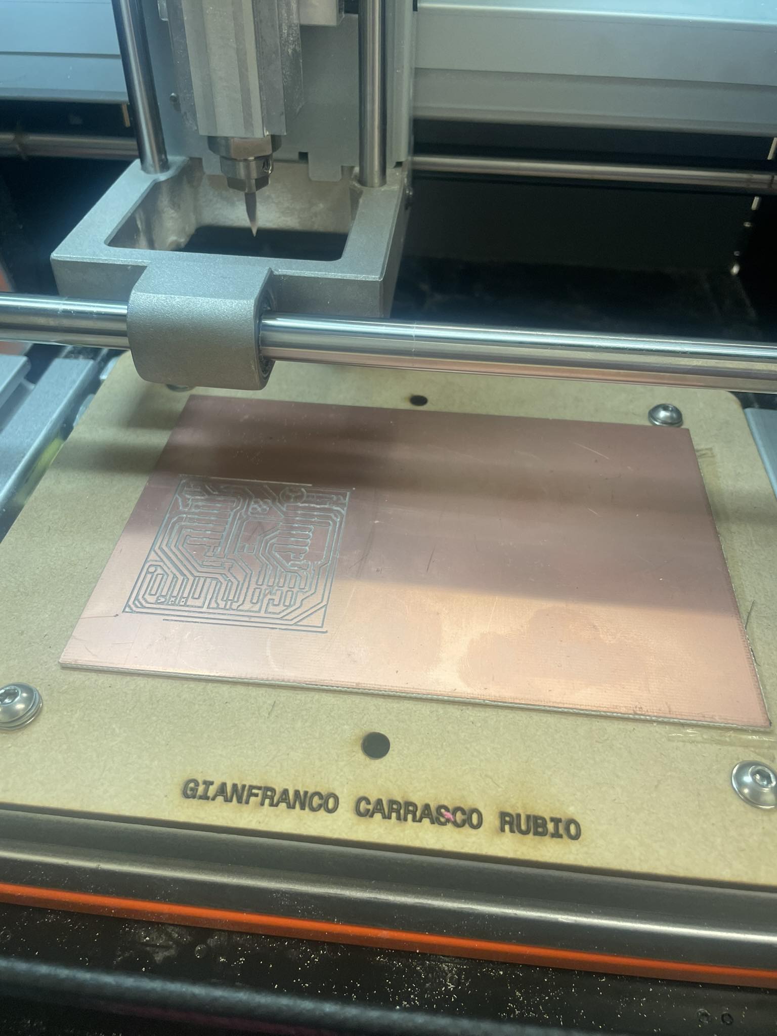
The strokes already generated in the following image:
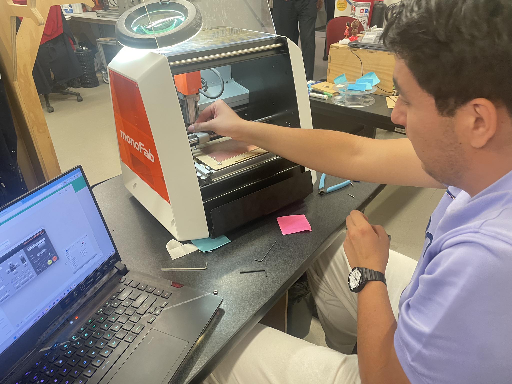
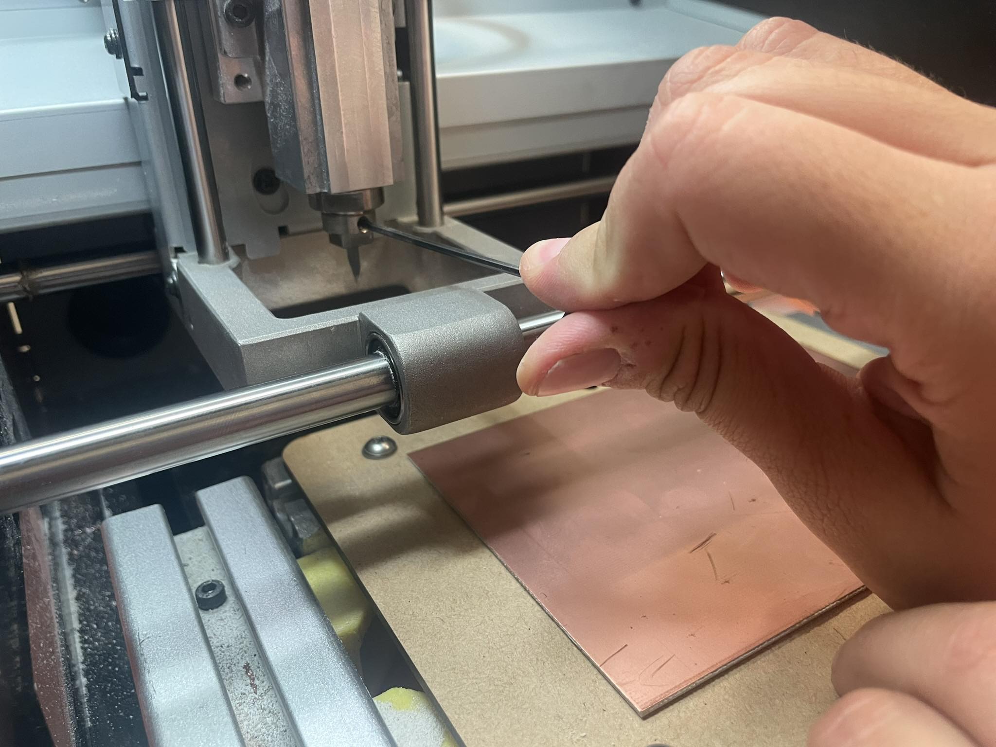
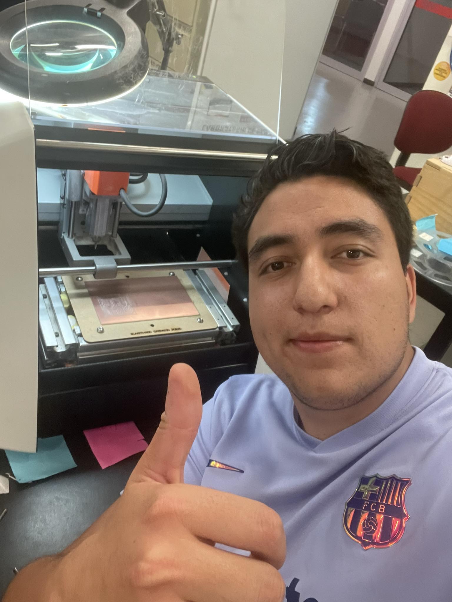
Me using the machin, calibrating and puting the correct tools
Calibrating my sacrifical board
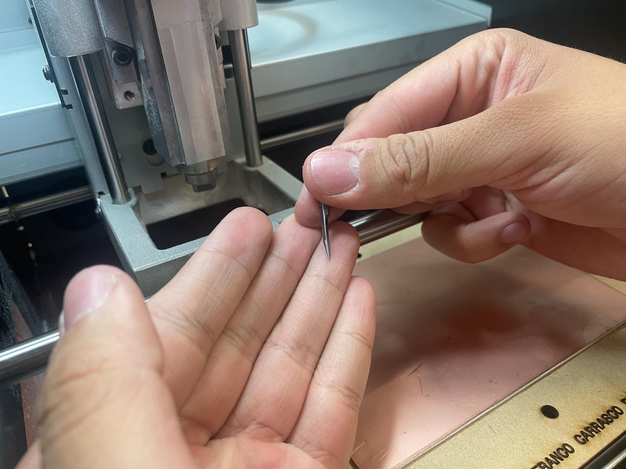
This is the part where I select the right tool, for this practice, I had to use TWO TOOLS, one for the path tracing and one for the plate cutting.
This is a test that was carried out in order to choose the right tool and to ensure that there would not be any type of fault in the tracing, the most important part.
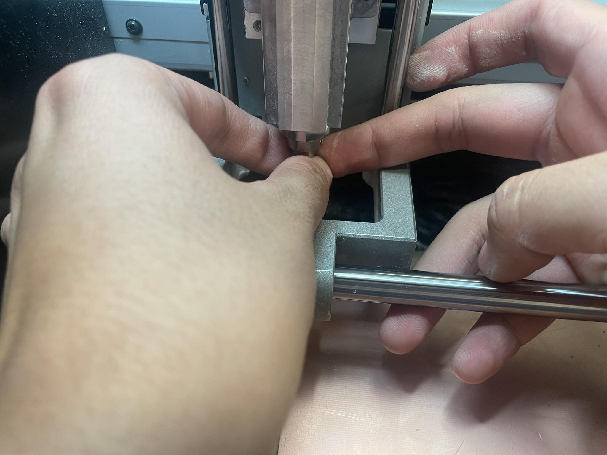
In this part you have to calibrate the tool in relation to the working area, you have to configure it, set all axes, x, y and z, to 0.
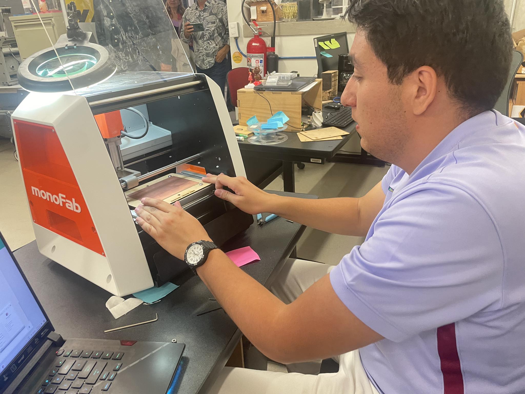
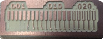
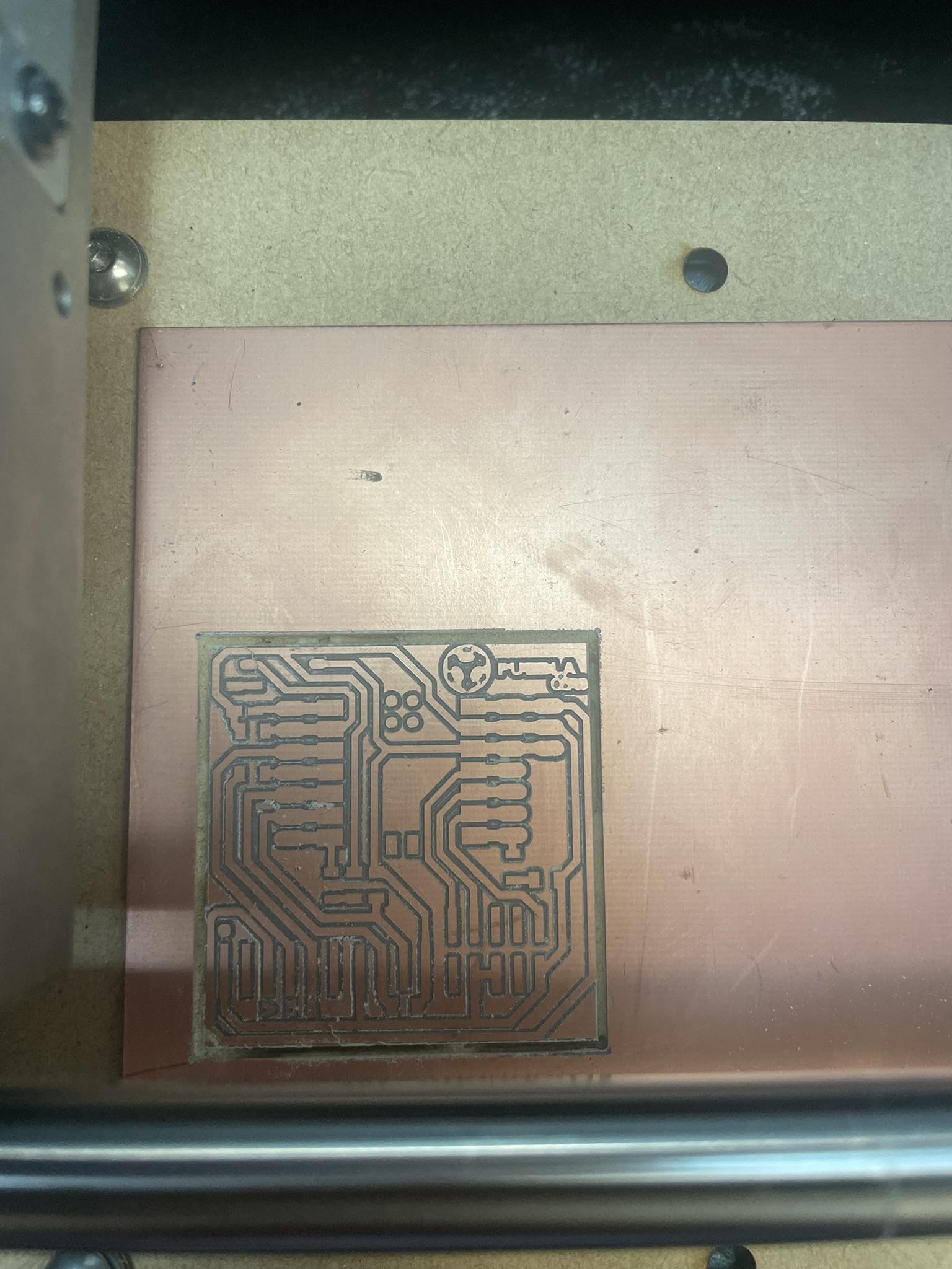
The plate with the traces already made
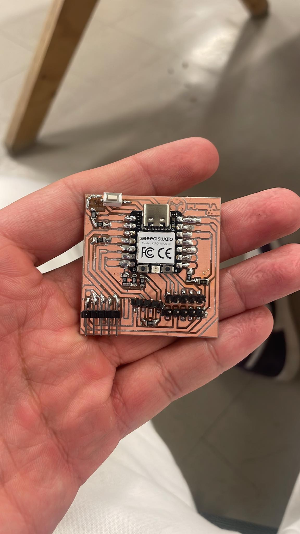
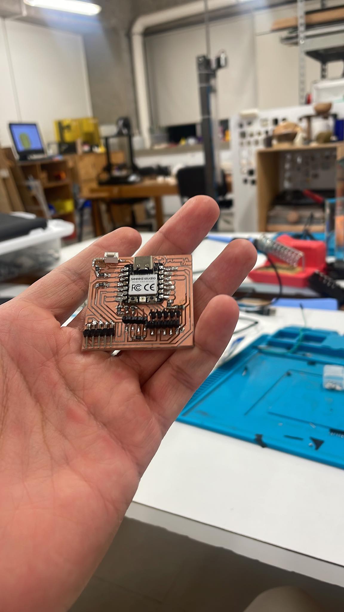
ME AND MY PCB
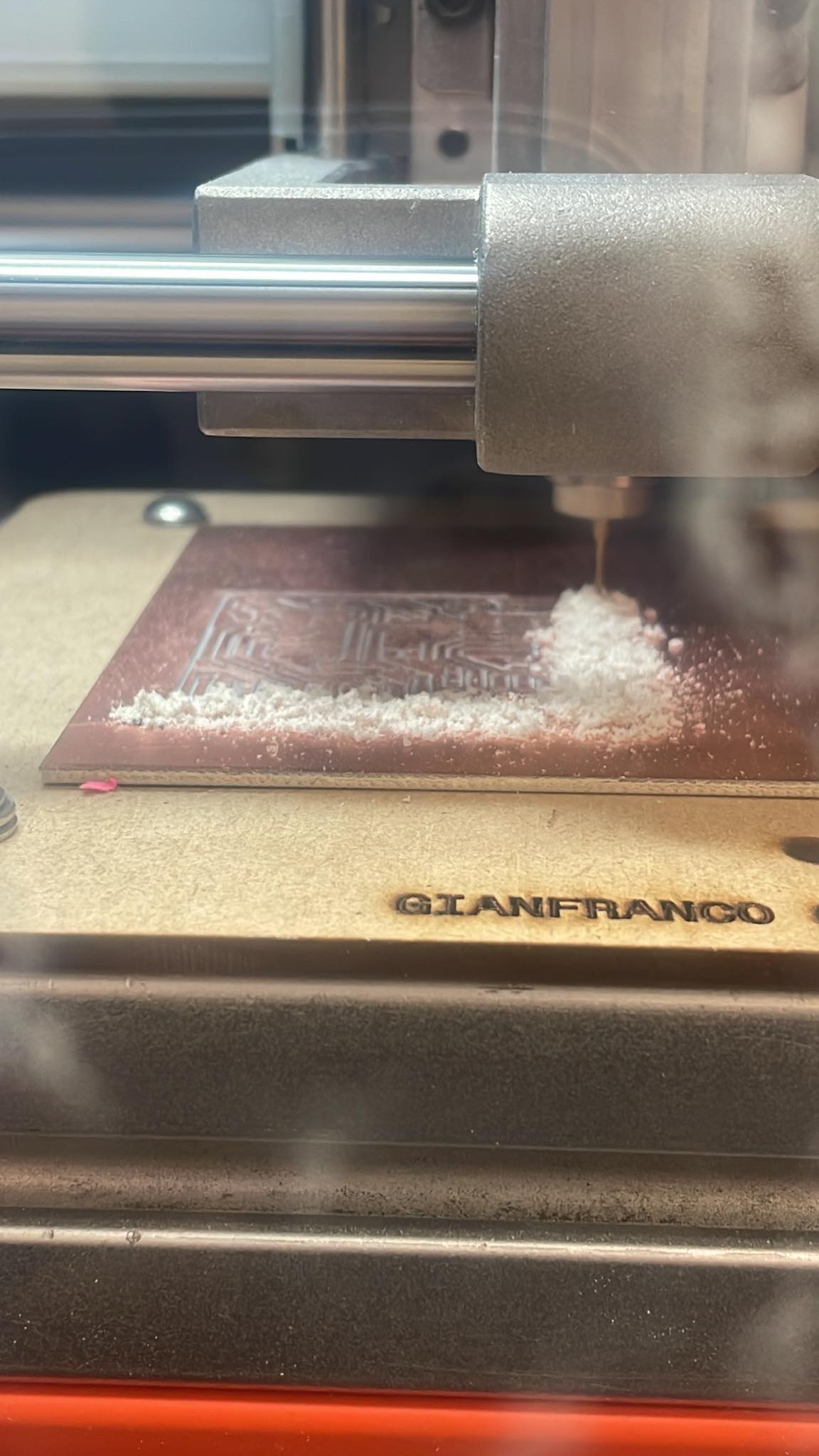
And then the final cut
The finished pcb inside the machine, as seen through the glass
Me again
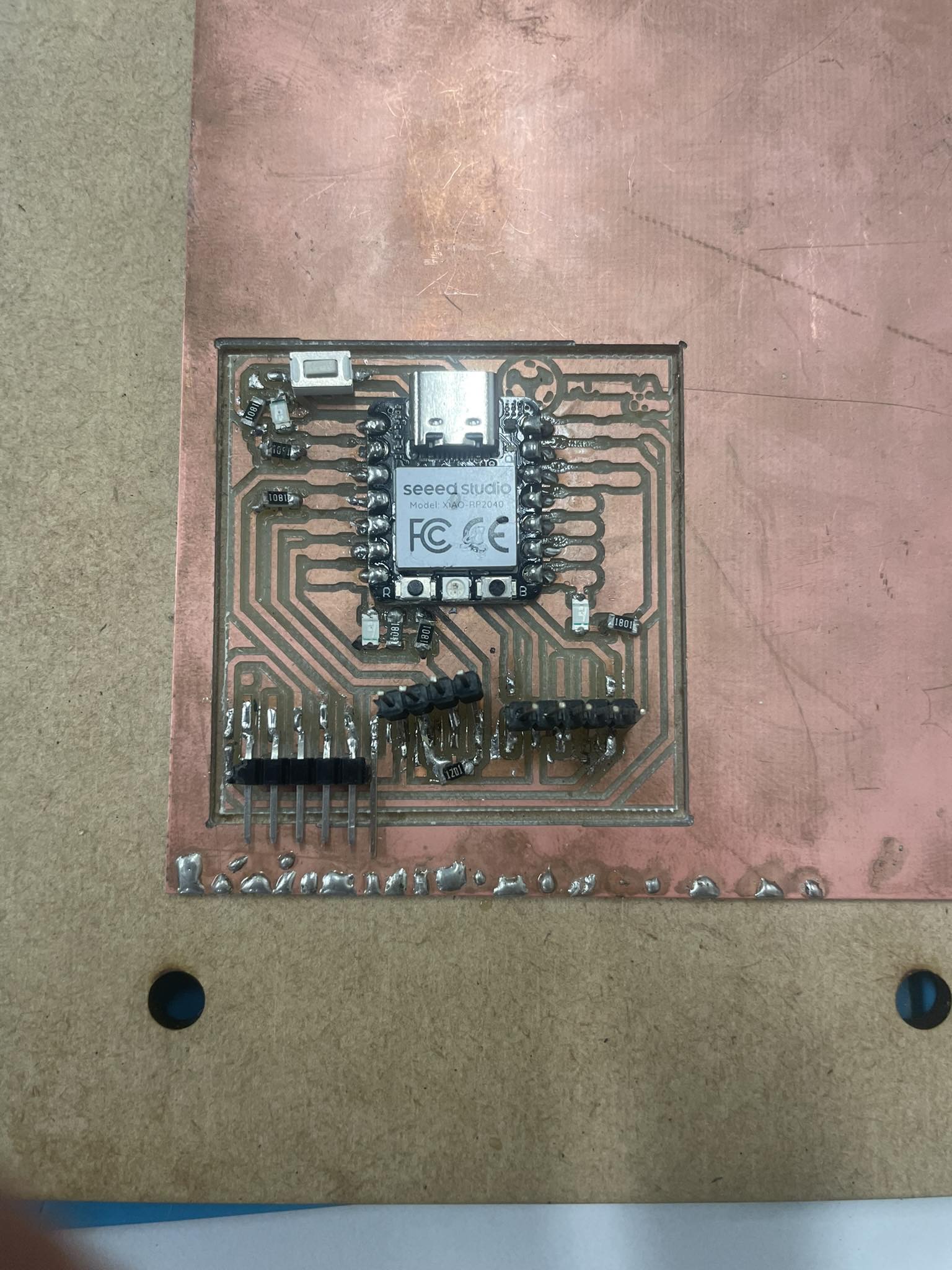
After having everything ready I had to solder my board, the elements that I put on it are the following:
XIAO RP2040
Push button
2.2K Reistor
1k Reisitor
LEDs SMD
Pin headers
Final result
- © Untitled. All rights reserved.
- Design by : Gianfranco Carrasco Rubio