WEEK 3 -Computer-Controlled Cutting
Design, lasercut, and document a parametric construction kit, accounting for the lasercutter kerf, which can be assembled in multiple ways.
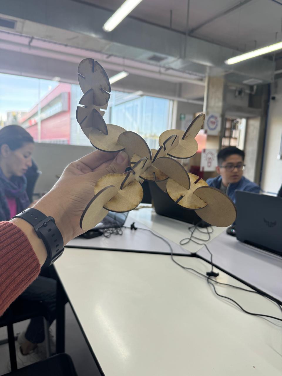
The first step to do a parametric construction kit was found inspiration, and this was "LOS TAZOS", a popular toy in 1900's & 2000´s that you could have when you bought chips, cheetos, doritos, etc.
In the week 3, I decided to make my parametric figure in CATIA, one of the best softwares for 3d design (for me)
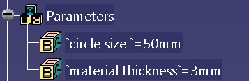
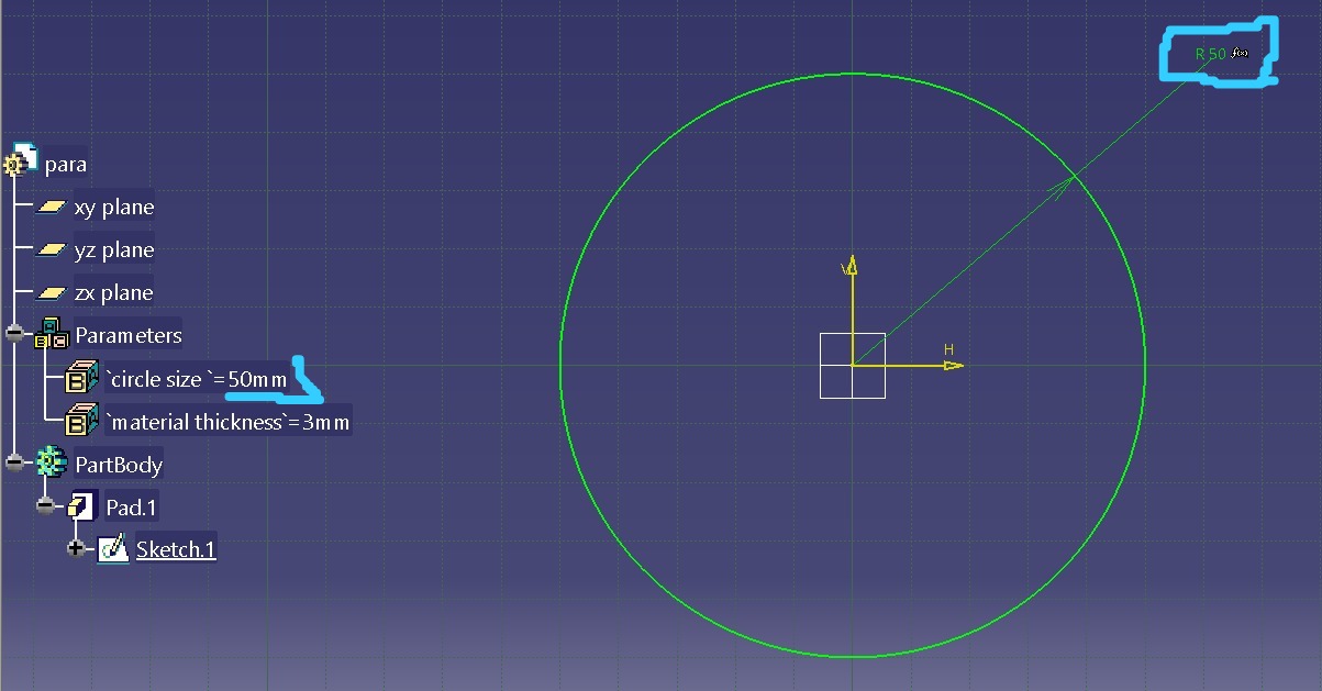
The first step I took to carry out this activity was to declare the first main parameters of my figure, the principle ones, circle size, in this case i can change the lenght to the size i want, and the second one was material thickness, this parameter is important to have,
because thanks to his parameter i was able to have a very good kerf.
In the next pictures, i will show every step i made to deliver successfully this task.
The first step was to make a circle, and the size of the circle was the first parameter i made, "the circle size".
When i made the pad for my figure, the proccess to make 3d, I use other of my parameters, material thickness, for the width of my circle, i put 3mm, because the material I used was MDF, ans his width was 3mm.
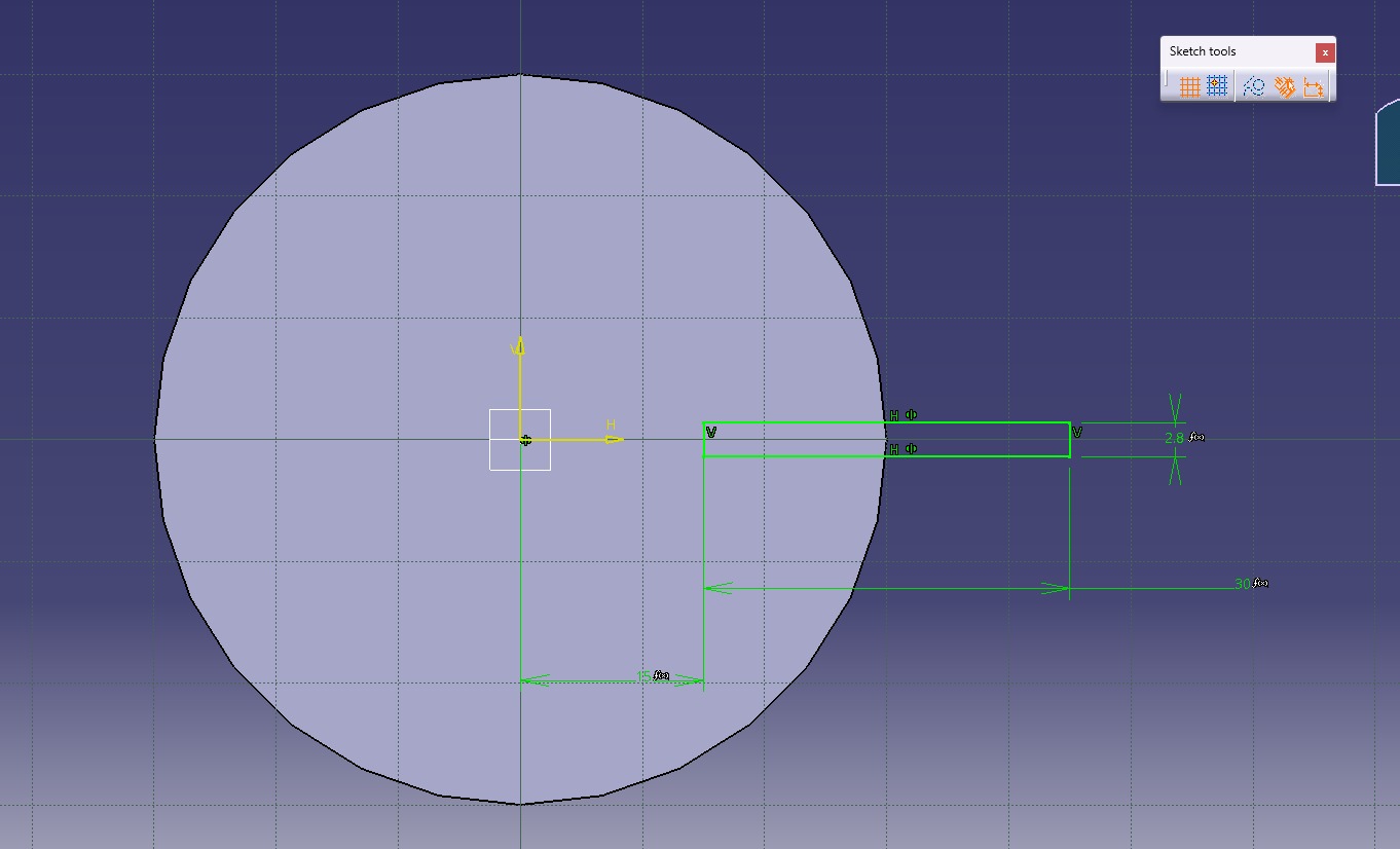
In the next step I had to create the space with which the pieces were going to fit together, in the image you can see 3 different measures, ALL parameterized, mainly the measure of the width of the space to fit, which was created a parameter called "KERF", which will be explained later, as well as another parameter called "embone depth".
You can see the rectangle previously made but already previewed in 3D.
This step was the one that I think was the most complicated to make my figure, since I had to create a parameter called "degrees of a circle", I could say that it is unfeasible, since I did not use it directly, but to use a mathematical formula that allowed me to divide the "instances" (the spaces of my circle) in a symmetrical way.
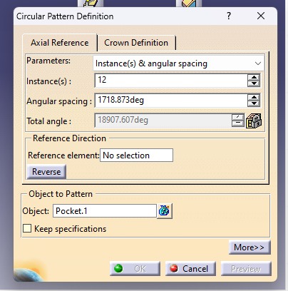
It is important to look at the data that we will need to put in at a certain time, to understand why use each of the above mentioned parameters. The first of them Instances, then angular spacing, this is the one that will have more importance, since this will be in charge of separating each one of the spaces in the total area of the circle.
Finally the "reference element", which is important to make a circular pattern, for this we have to click on one of the front faces of the circle, so that it knows where it has to move, lastly the "object" that we want to be pattern and multiply as many times as we want.
Now with the parameters adjusted, with the correct measurements, you can see in the image that all the data that before had decimal numbers, are now closed numbers.
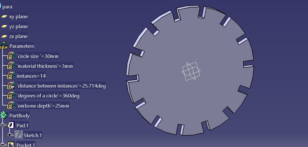
Parameters
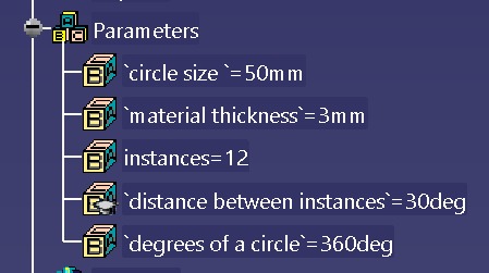
The parameters shown in the following image are all those that have been used so far.
IMPORTANT TO WATCH
.
In the previous image you can see in the parameter "instances" that has 12, so in the 3d design, the figure will have those 12 spaces, and exactly that can be seen in the following image:
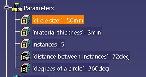
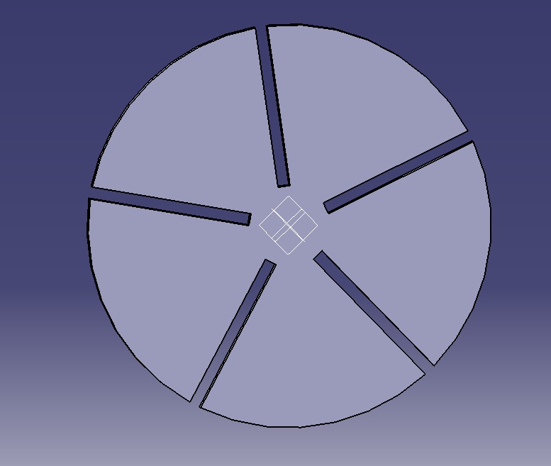
In the following 2 images you can see how I keep playing with the parameters that I have already configured previously. This time I change the size of the circle, the material thickness I can't change it, since I will always use MDF of 3mm, the instances I also change them by 5, to reduce the number of entries.
I decided to add a new parameter to change a little more the figure, since I like to complicate things haha, this time I added a parameter called embone depth, that what it does is to make longer or shorter the entry of the "instances", as this can allow more creativity when making a figure with this assembly kit.
In the following images you can see the embone depth with 20mm, so the long entry, on the other hand the following image with 40 mm, is very small
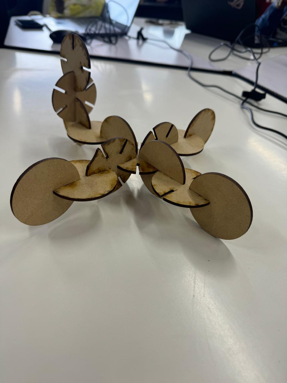
With this last image I want to make clear that the possibilities are too many, you can make different sizes, which allows you to enter a huge world full of possibilities, full of creativity where you can put together many things with a complete construction kit, I really feel very happy with the result
|
 |
|
|
 |
|
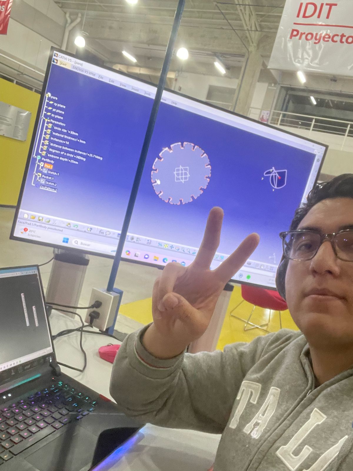
This is me designing my figure, I was really happy designing it, I really like the world of 3d design
I've been very happy designing it, I really like the world of 3d design
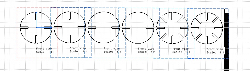
Now in what would be one of the last steps, is to pass the design to a working plane in 2D, in catia the module to do that is called drafting, and as you can see in the image, we put our figure as if it were a front view, so that in this way you can see each of the details that we designed previously
.
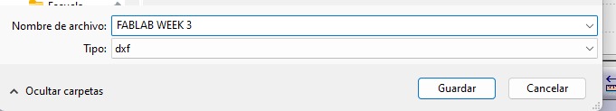
When I had the complete file, the next step is to save it, we have to save it in a specific file, it is called "DXF", which is the file that reads the SMART CAVE program, program with which we configure everything, from laser power, laser speed.
In the following image you can see what was commented in the previous point, the configuration of the parameters of use for the laser cutter, in the image you can see 3 important things
-
Colors: The colors are of utmost importance to separate the parameters of one thing or another, for example, if you want to cut a circle, but inside it you want to make a detail, you put other parameters.
-
Max power & Min power:Estas son las potencias máximas y mínimas con las cuales el láser va a cortar. For this week, we cut 3mm MDF, so it cuts at a maximum power of 75 and a minimum power of 65.
-
Work speed: This is the speed at which the laser will pass through the marked areas. On this occasion it is recommended that it is 25, since what we are looking for is the cut, but if we only want to make an engraving, it is recommended to use above 190.
The following image is the exact graphic representation of how it looks in the laser cutter program, a blue color representing the vectors of our figure, configured to be cut at a previously set power and speed.
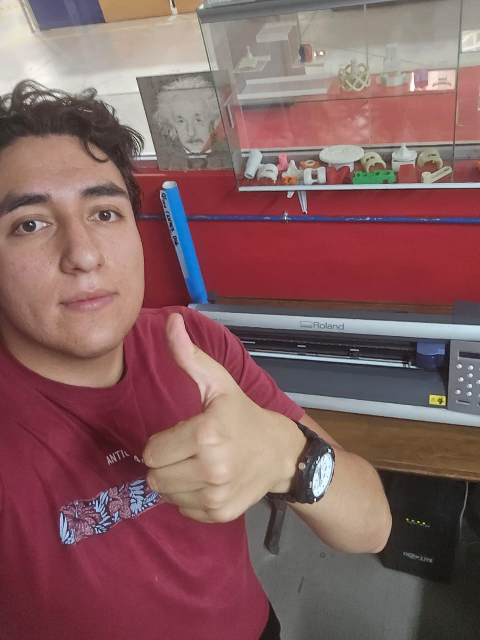
This is me on the cutter, cutting my parametric design.
It shows how my figures were being cut one by one.
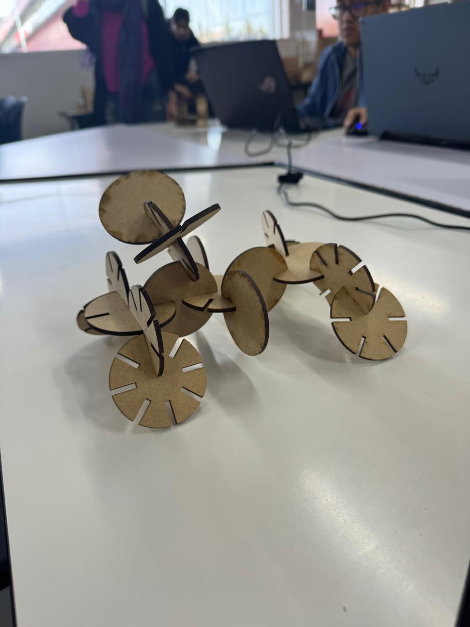
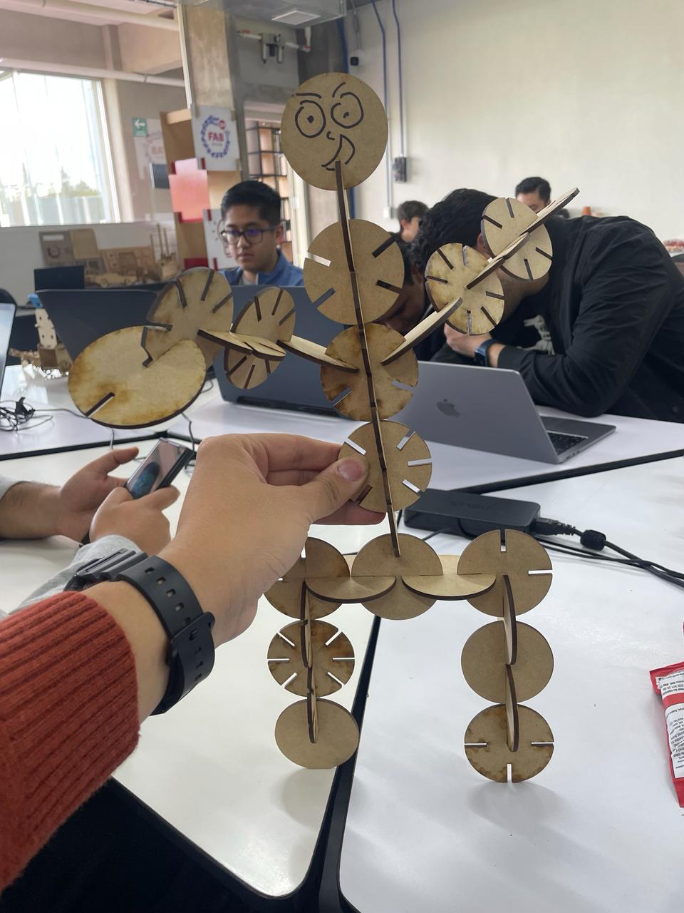
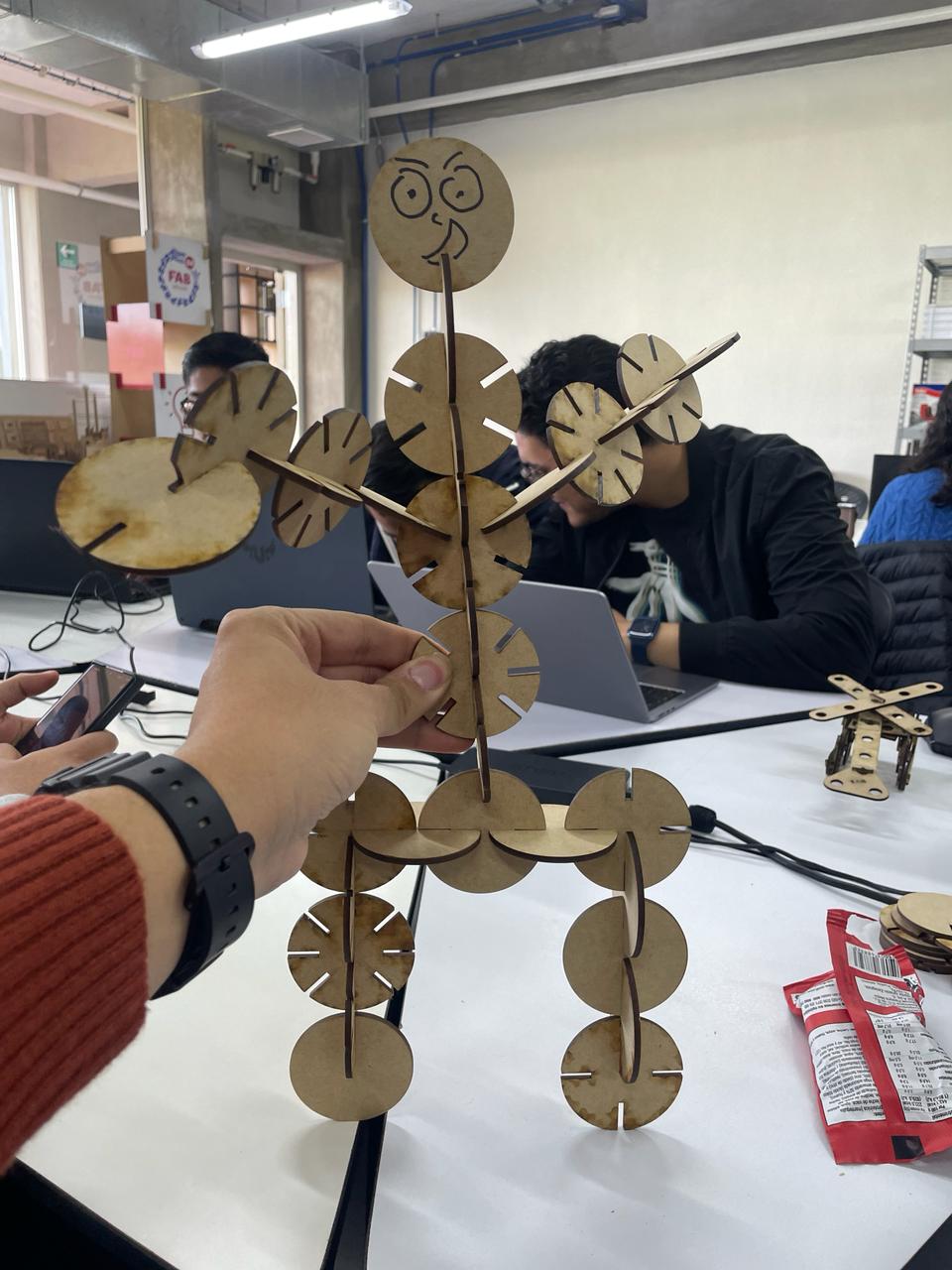
AND NOW MY HERO SHOTS:
My new motorcycle (220 MPH)
MY OWN PRIVATE JET B)
AND MY NEW MATE: RIGOBERTO HERNANDEZ HERNANDEZ DEL SAGRADO CORAZON DE LA SANTISIMA TRINIDAD DE LOS ANGELES HERNANDEZ
Cut something on the vinyl cutter.
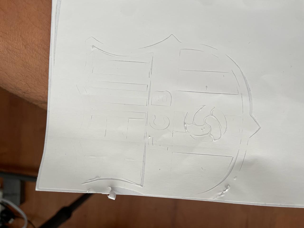
My image of inspiration was the club of my life, the club of my love, the FUTBOL club Barcelona.
.
I vectorized my logo in 2d illustrator software, in which all the process that I made can be seen in week 2, CLICK HERE to see it
.
In the program that is connected to the vinyl cutter, this is how our vectorized logo looks like, the format in which the processed logo has to be saved is EPS format.
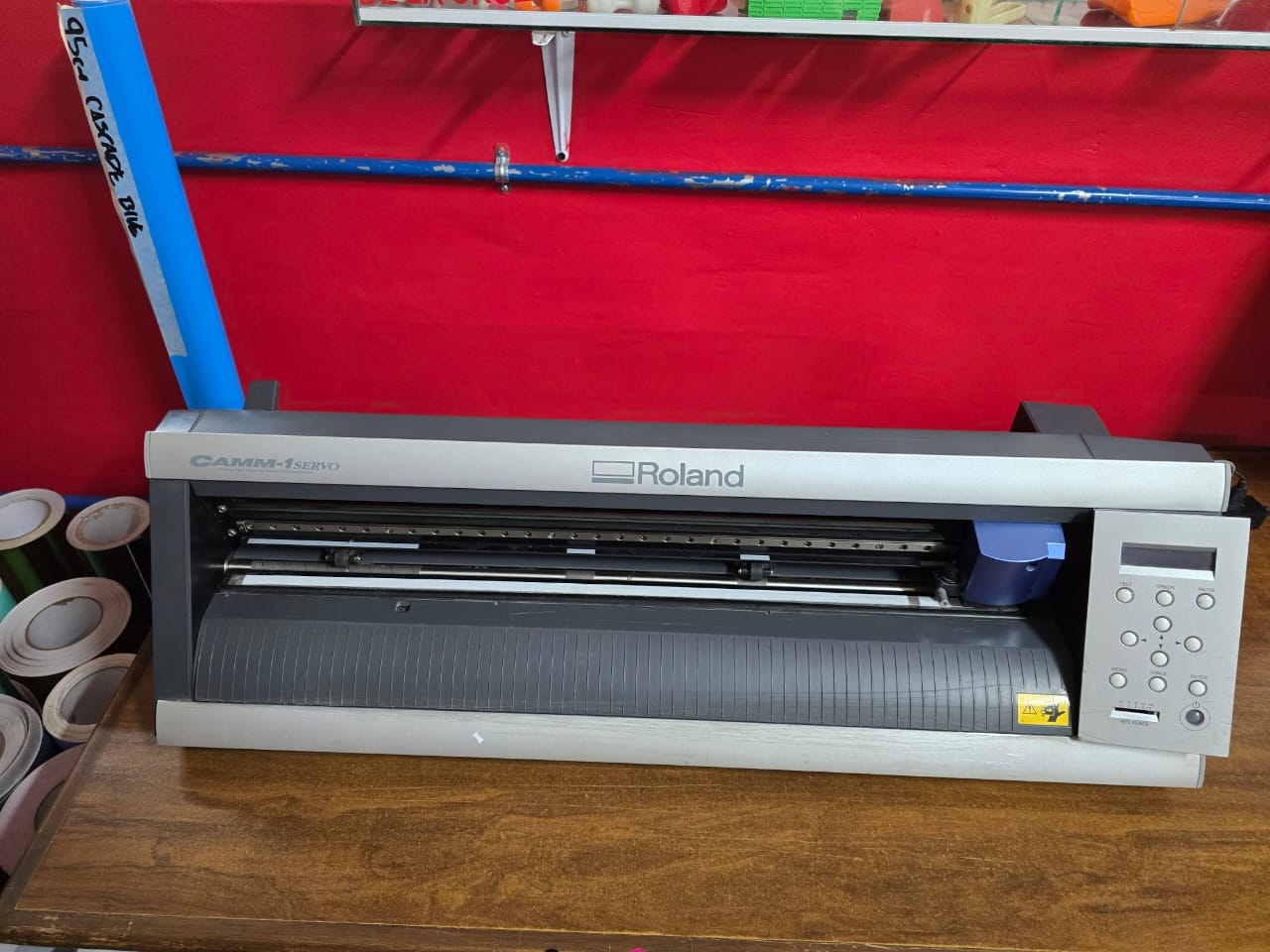
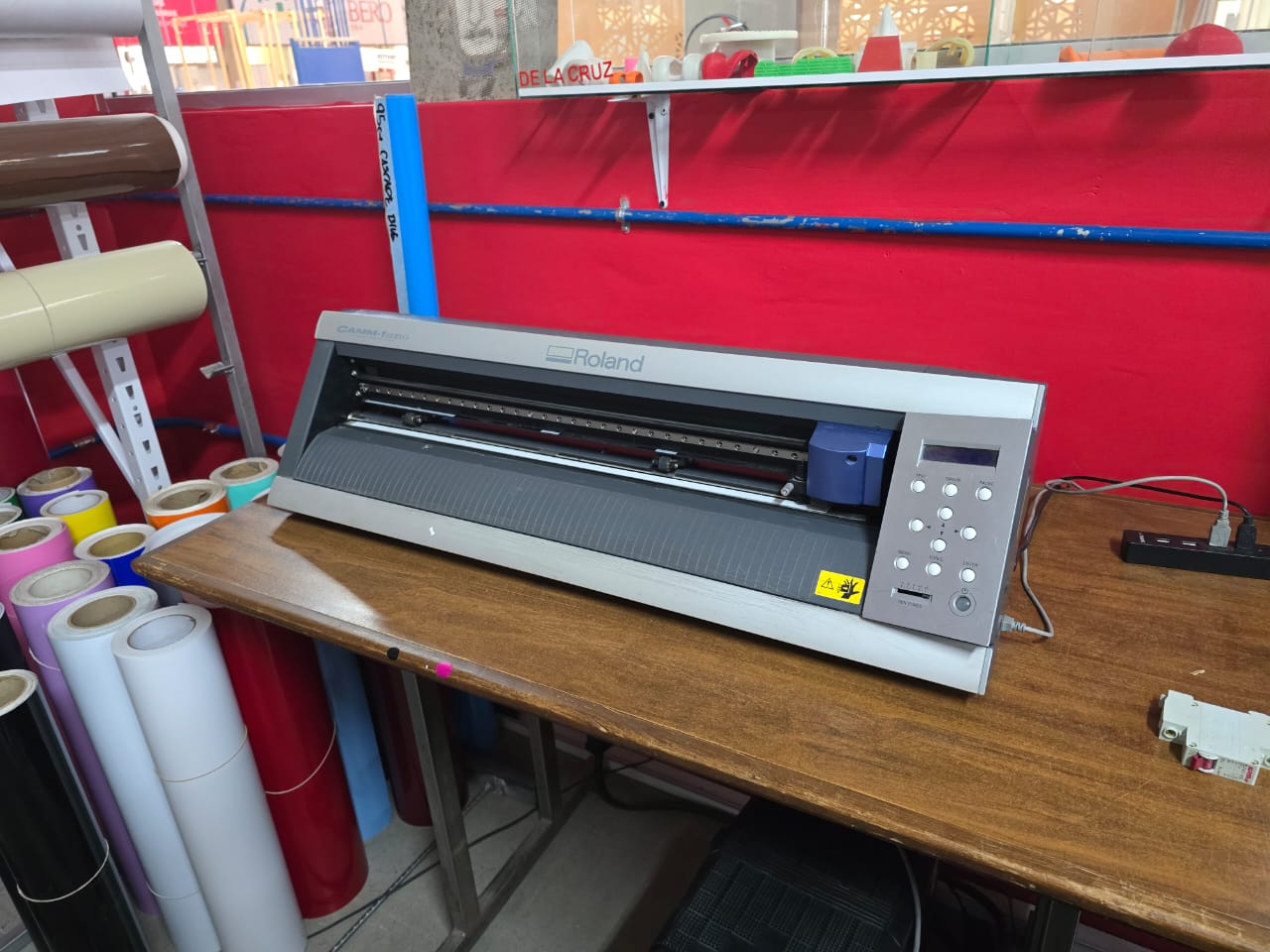
this is the vinyl cutter with which I developed all my week, this cutter is in our FABLAB lab at Ibero Puebla.
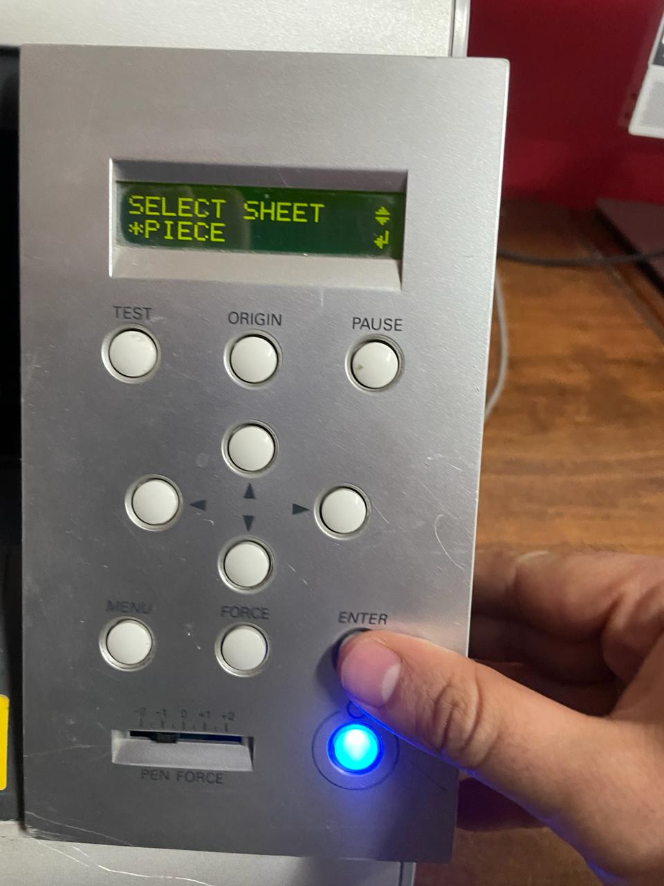
When you first interact with the vinyl cutter, it asks you if you are going to cut in a small piece or if you are going to cut in a roll, (which is for much larger cuts than the one shown here).
I use this option: PIECE
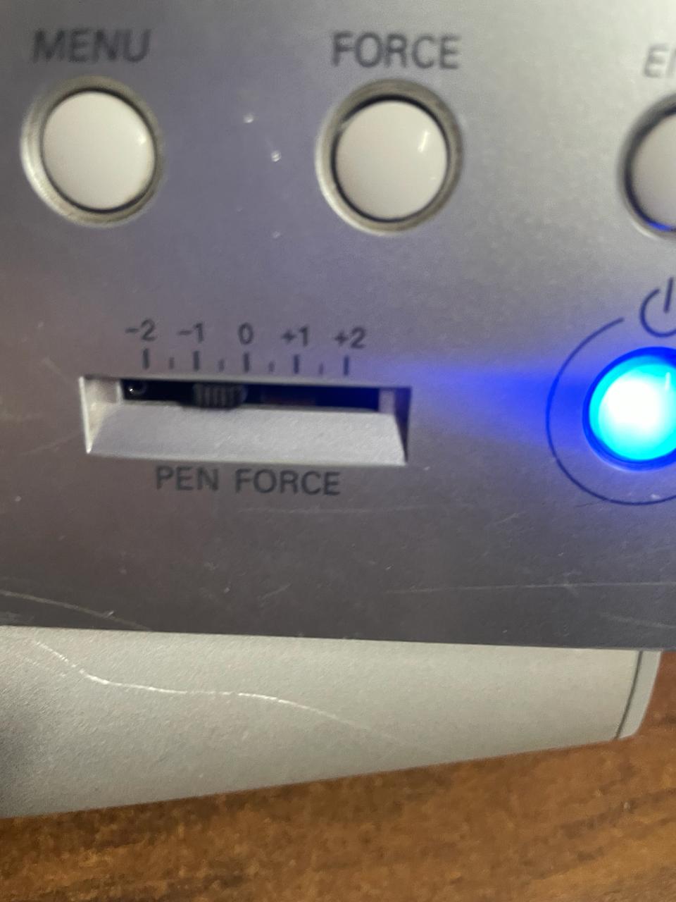
Now the next step before clicking on the "CUT" option, you have to configure the force with which the PEN will perform the movements, as you can see in the following image had 5 different speeds: -2,-1,0, +1,+2
These are the results with the different powers of the pen, I only used from -2 to 0, because the 0 power was too strong, so I decided not to try other powers, the 0 power was so strong that it moved my piece of vynil and made a cut in my work :( (attached evidence)
The following image was the best, the one I liked the most, since it had no details, it was with the power -2
- © Untitled. All rights reserved.
- Design by : Gianfranco Carrasco Rubio