7. Computer controlled machining
For this week the practice consisted on making something big on a CNC Machine. The term CNC applies for the tecnology used for Computer Numerical Control and can read the same type of files as a Laser cut, so I thought of it as the tool for bigger versions of 2D cuts. Actually, during this practice I realized this is more versatile, since It allows you to carve in both: 2D and 3D, so it can be useful to sculpt or make molds too. For this practice, I used a router
- The group assignment: Getting to Know the machine
The first thing we did was to recieve a safety guide on what to do and avoid during the making of our individual project, here are some important measures to consider:
- Safety equipment: Whenever you use the machine you must wear boots, an overall or lab coat, safety glasses and earplugs. Also, it is recommended to wear a mask because there will be a lot of sawdust around.
- Do not work alone: This is not mandatory, but we applied it since this was the first time using the machine of some of us. We worked in pairs to set the working planks ready and monitor the machine.
- Vacuum the sawdust: As the mill removes material, it will become dust that will lay on the surface or blow everywhere. This is flamable and may cause trouble to the development of the cut, so from time to time and inbetween external and inner cuts it is required to vacuum the surface. Also, before laying the material plank, it's necessary to vacuum the surroundings for safety.
- Mind the nails: In case your router uses nails as fixtures, try to nail them on the edges and corners, and also putting the design far enough to avoid the mill running over them. In case this happens not only the tool would break, but some pieces might flow away, so consider it before cutting.
If you're interested on learning about safety and performance tests we did at my Fab this week, click here .
Some basic concepts
| Concept | Description | Picture |
|---|---|---|
| Dogbones | These are the modifications to the corners of slots in a design in order to fit the shape of the mill. They round them and leave a simmilar shape to a bone. | 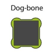 |
| TBones | These have the same purpose as dogbones, but are called T-bones because they have a shape that looks like a T. The difference between them is the amount of material removed per slot. |  |
| Tabs | These are small sections of material intentionally left attached to the workpiece to prevent it from moving or becoming loose during the machining process. |  |
| Sacrificial Layer | This time, the bed allows you to have a flat surface to attach your material to, so it's fixated for further cut or milling.When you | 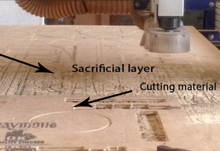 |
| StepOver and Overlap | It is the distance the cutter moves over when it finishes machining, considered in a percentage of the tool diameter. As the mill carves in a circular motion, you have to take care of the distance between the first time it passes, then its distance to the next one. | 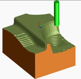 |
| Feed rate | THe Feed Rate is the cutter's speed per pass, if it's too high, the tool will stress. If you configure it, aim to cut at the highest speed possible without damaging the machine. | 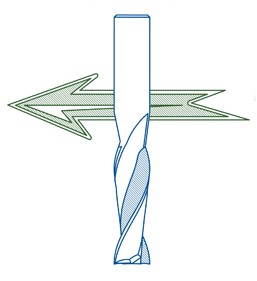 |
RPM | Ths stands for "Revolutions per Minute" and is the speed at which a cutting tool or spindle rotates during a machining operation. | 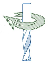 |
---- The design process----
- As we required to design something at least 1m³, I thought about some furniture that
might be useful for me. As I work a lot from my couch I thought of a side table to rest
my laptop on, instead of my legs, so the first step here was to make some drafts. Those
came out horrible because I didn't really have it clear (lol), so I'll place the
moodboard/inspo here instead.

- To understand what I wanted, I took many measurements from the floor to the ideal
height where I put the laptop. Then I realized I also needed a place to put my laptop at
my bedroom, because I like to watch movies from there but I usually rest it on the bed.
While measuring I realized there were different heights, so I decided to make it
adjustable.

Attempt 1
- I started to design using Solidworks. To make the pieces I measured my laptop as
well and started to draw
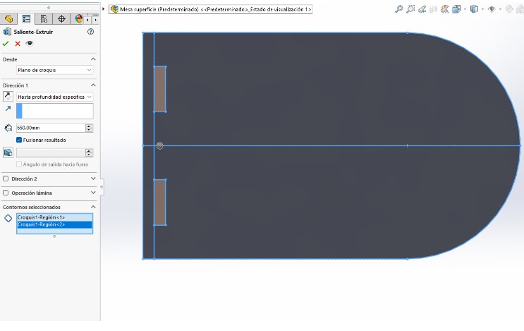
from the top piece, using a rectangle with the measurements as a reference.

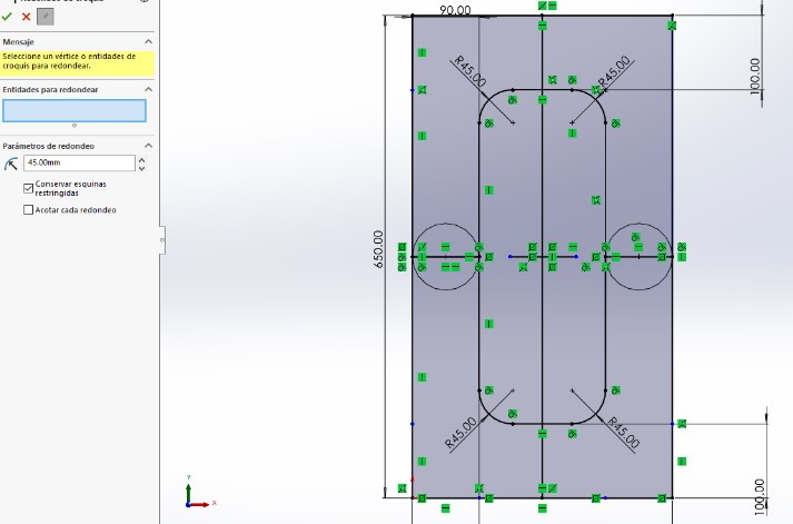
- Then I rounded the shape using a tangent arc and drew the rectangles that I
wanted to turn into slots. I also gave them the same height as the material thickness.
- Next, I cut the lines I didn't need and extruded the shape 15mm, as it was the thickness
material I would be working with. Note: All of my pieces had the same extrussion
depth. .
- Now, using the same sketch of the table board, I extruded the slots to the opposite
side, making the table legs.
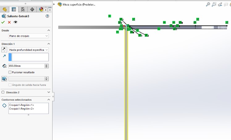
- As the legs were too squared, I decided to draw on the wider face another sketch. This
was supposed to make them look more simmilar to the first piece. I also made the sketch
in a way I could use it for theupper and lower legs of the table.
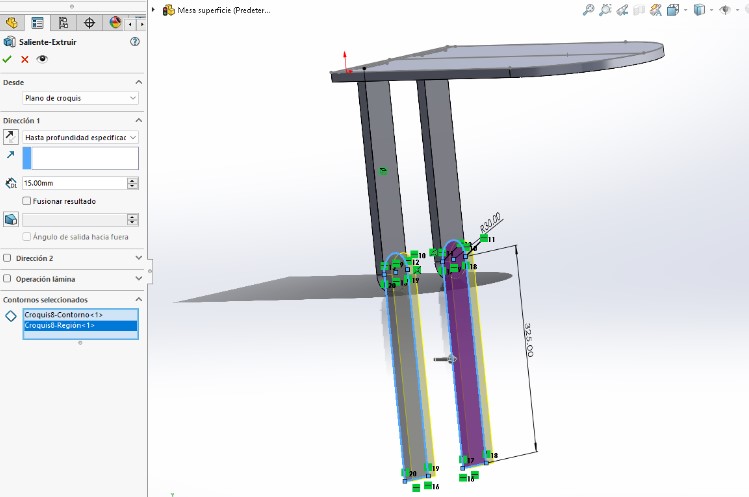
- In the middle of this, I came up with the idea of extruding each leg in opposite ways.
To do so, I made separate extrussions, making sure I wouldn't merge the pieces.
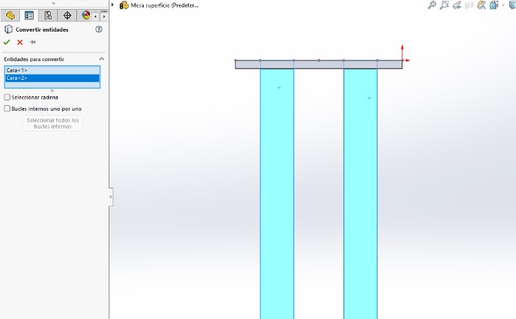
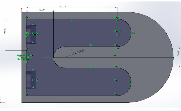
- Having both parts of the legs, I took the bottom face of one and started a new sketch.
Then copied the slots from the first piece, using the convert entities tool. I
used it as a reference to draw a shape for the base of my table.
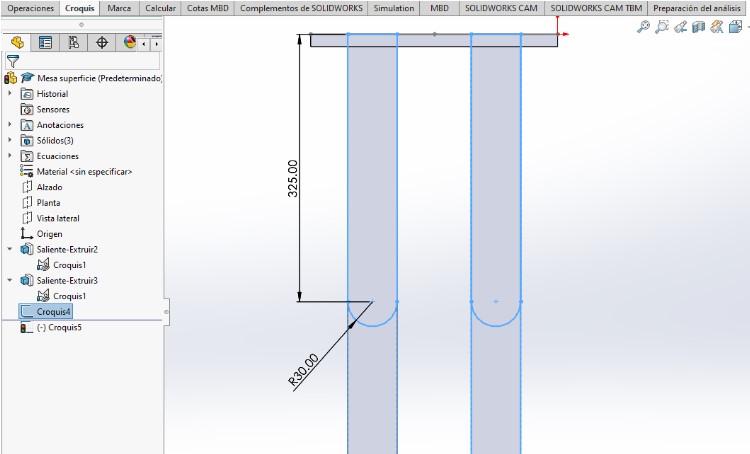
- The final step I did was to extrude it. When I did, I hadn't finish the design, but by
looking at it It seemed as I call it Soulless, so I decided to stop this design
here
and try something different.
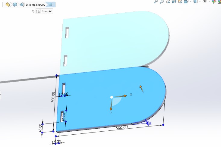
- As I felt I needed something different, I made another design that included more
curves and soft shapes. I also made this differently, by starting to draw inside
of a square the size of my MDF plank. Just to check that all the pieces would
fit.
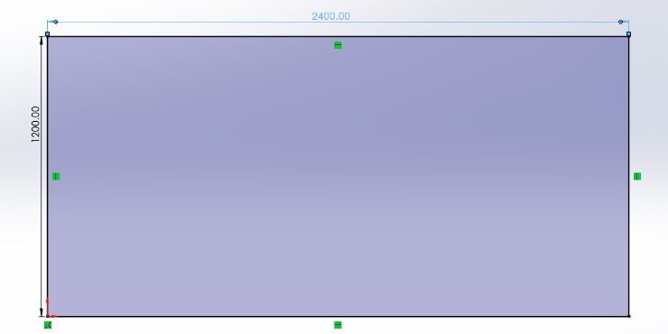
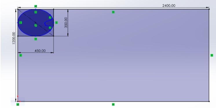
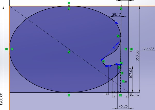
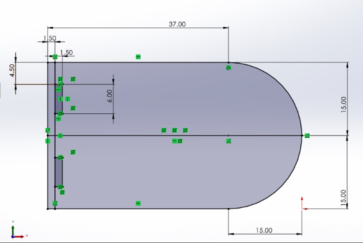
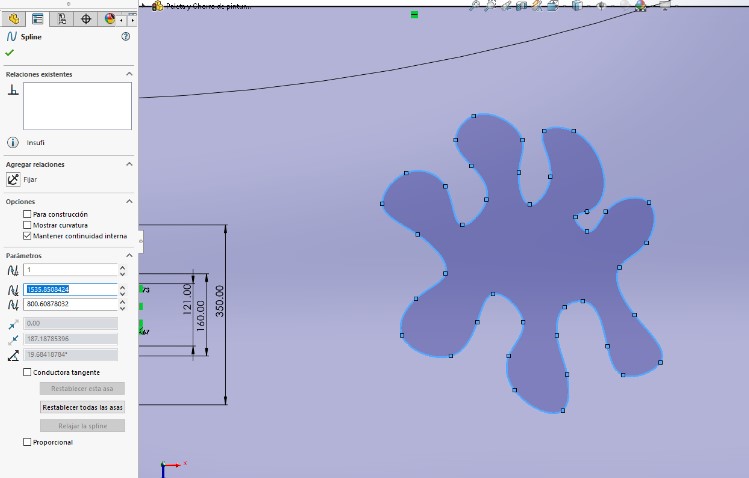
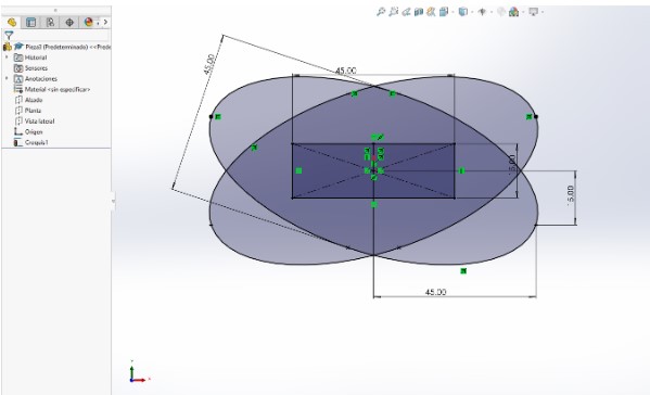
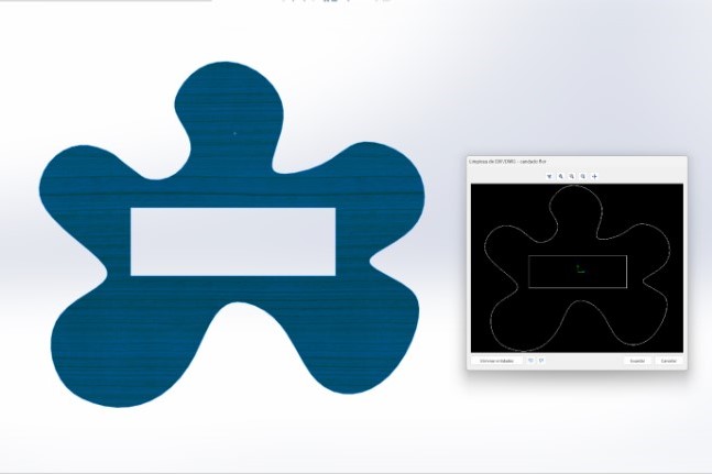
- Again, the first piece I made was the top piece, but this time I drew from a concept. I've always liked art attack and the fake props and furniture that resembles painting tools. So, my first piece was inspired by a paint palette.
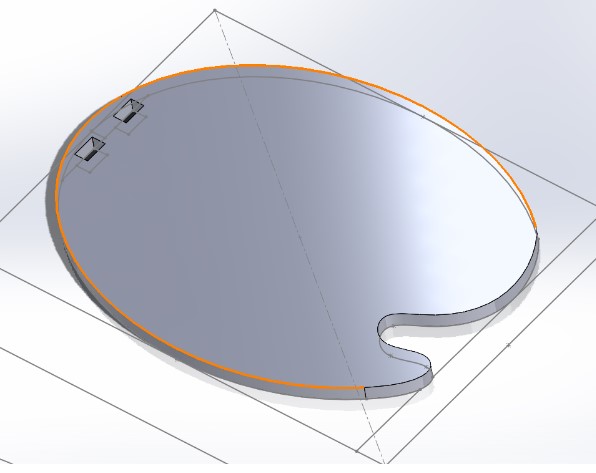
- I drew it from an oval and added more lines to change the shape. As it had more organical curves, I had to define it by adding a lot of dimension lines. I also moved some points until It got fixed.
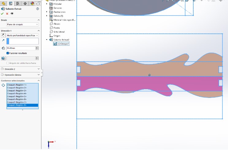
- Once It was ready, I extruded it to the material thickness.
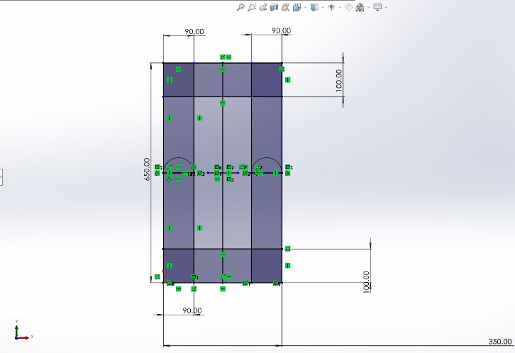
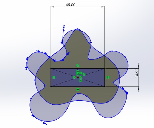
- I did the same to draw the legs, starting by drawing some base rectangles with
the desired shape, then drawing inside of them. Here I tried to make it look
like paint dripping to the floor.
- Then I extruded it, it looked more lika a tree branch, but I stayed optimistic.
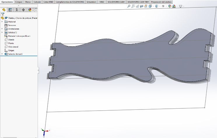
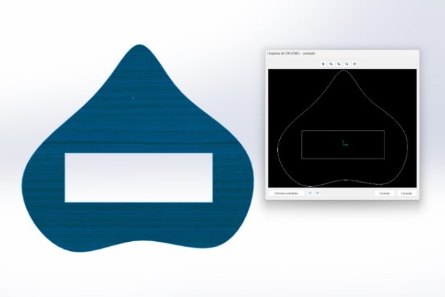
- Finally I made a paint stain for the base. I liked it a lot when I
extruded it, but the whole concept didn't convince me, so I didn't draw the
slots for the assembly yet.

- To test the assembly of the parts, I exported each extrussion as a different field and used the assembly tool from SolidWorks. Here I noticed that probably the design was ok as a concept, but too much to continue, so I changed my mind again!

Final design
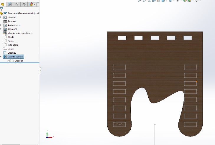
- At this point I made more drafts and went back to the original Idea, but
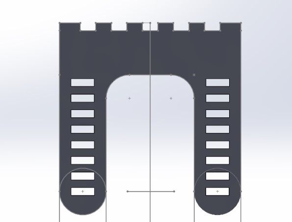
made some changes, starting by drawing from the legs. I made a frame with
the ideal measurements and inside started to draw the legs, but this time
there were 2 instead of 4.
- The shapes were mirrored, so I had a better look now. I added a
fillet and extruded the original piece.

- Now I applied the same strategy as in the first attempt, of trying to mirror the seconf piece to the opposite side.
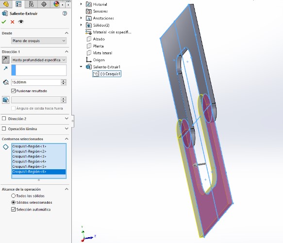
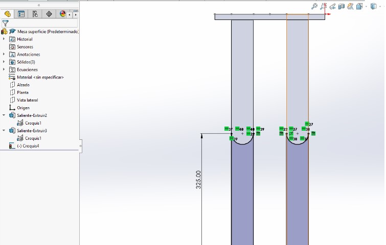
- Having the piece almost reafy, I added the slots (more this time) to make the links for the assembly. This is how both looked.


- Then I drew more slots and made extruded cuts to the pieces, both: the upper and lower one. Here I also restricted the chances of assembly to have a max of 65 cm tall. This is how it looked like.

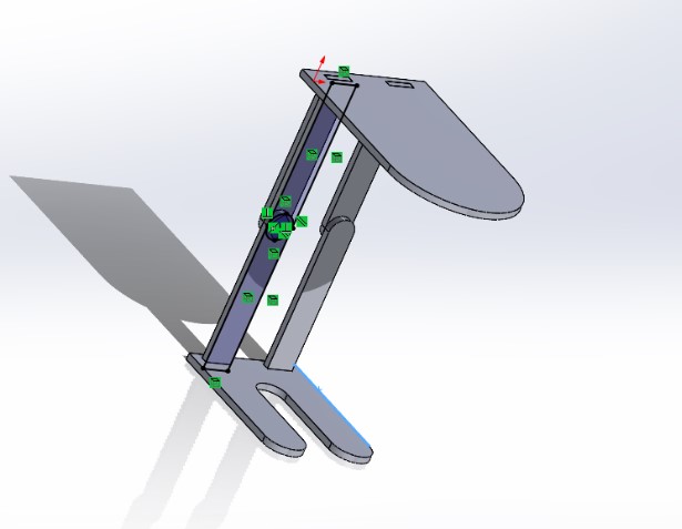
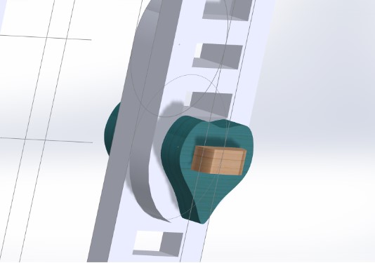
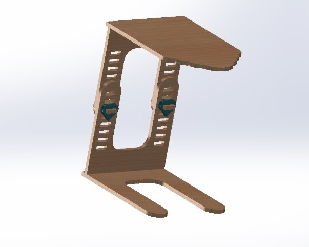
- Then I made a piece to go through the slots and link them. I put them together at the assembly view to check how they looked together.

- As the transversal piece wasn't secured enough, I made another piece to work as a lock to it. I started to test different designs to check which looked better.
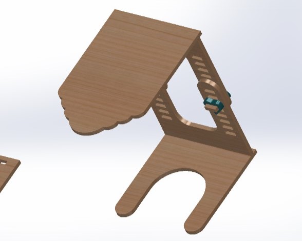
- Next I duplicated the base piece as the base for designing the upper surface. I kept most of the original piece, but the end was different. In the end I chose the one that looked like a cloud.

- Finally I checked the assembly of all the pieces together.
---- Making the toolpath and cut ----
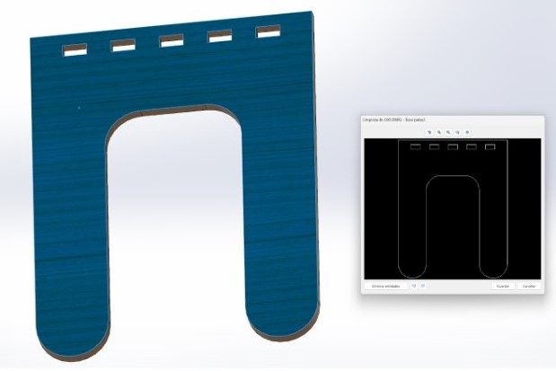
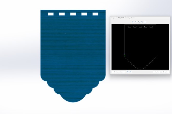
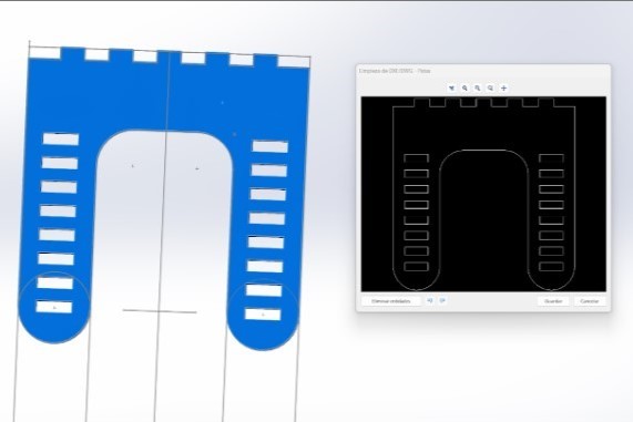
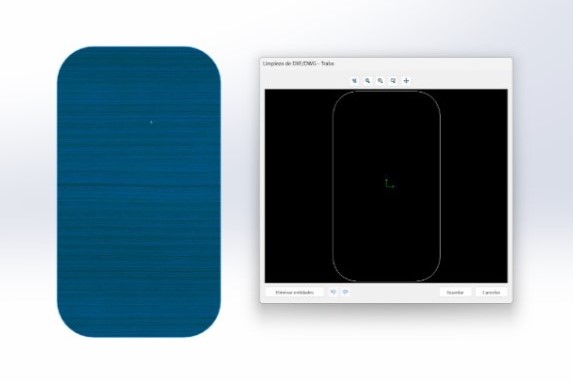
- The first step was to export the pieces on a DXF File, because they
would be vectors. There I chose to export the main faces of each piece.
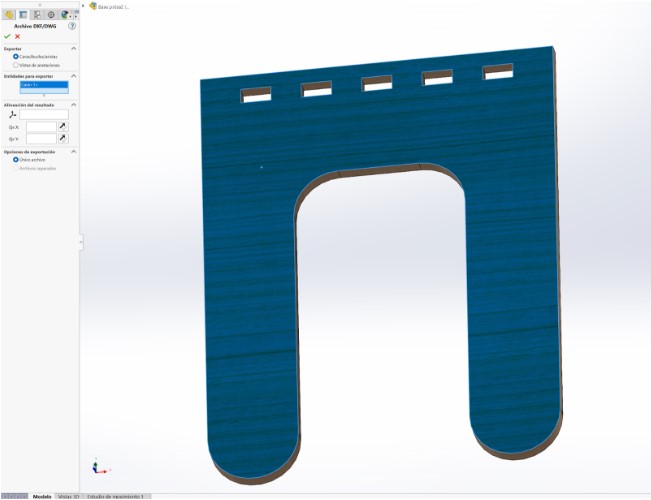
- I did the same with all of my pieces, so I could get to have a preview of
each before saving them.
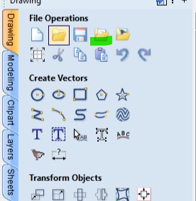
- Next, I opened the software to make the file for the actual cut. The software I used was V Carve Pro. It offers a free trial, so I started to preview the pieces there, but if you use it, consider that it won't let you export a file to different versions using that plan.

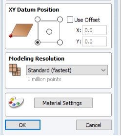
- Once I was in the software, there appears an option to modify the job size, that is basically the measurements for the material you will use to cut.There you can also set if it will be 2D, 3D or the origin you want to start the cut.

- Then It was time to look for the files. There is a tool that allows you to import files on the current "job", so it won't give you trouble. If you add files from any other import option there's a chance that it will open a new file.
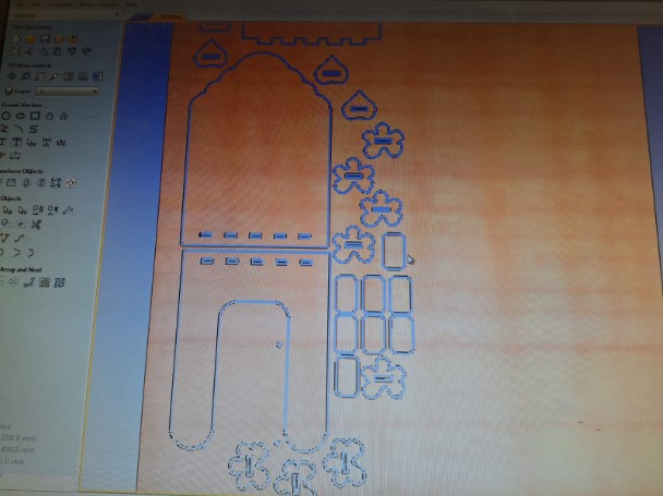
- This is how It looks once you add a file to it. Since I made my pieces on SolidWorks, it had a watermark as well. I just had to select and delete it.

- Something important, is that when you add a file, the lines may not be connected, so the software has a tool called join vectors . It's really helpful, because when you select a group of lines it will tell you how many are closed and open. I recommend using this tool shen you have several pieces already.

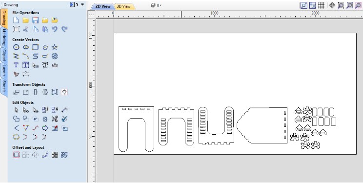
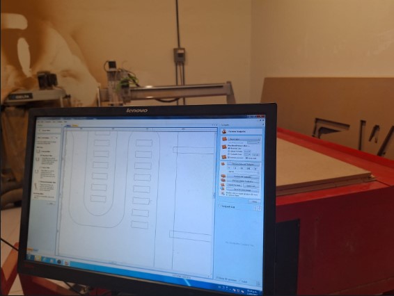
- Next, I started adding all the different parts to the job, trying to accomodate them with enough space inbetween and also copying and pasting variations of the measures for the adjustable pieces. To modify these, I used the set size tool.

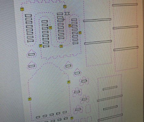
- This is how it looked like with all of the pieces added to the job. As you can see, I left some space between pieces, at least 2 cm before the next one.
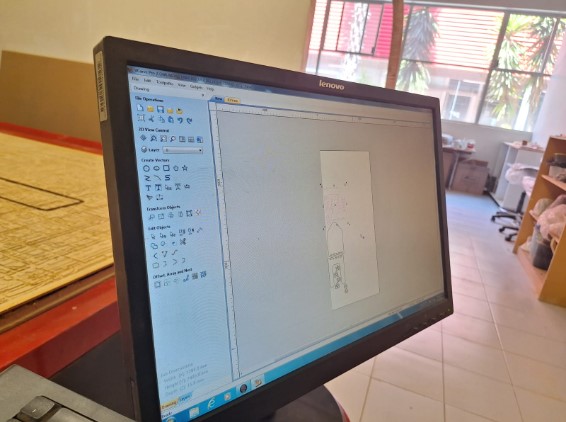
- A little spoiler: Make sure youre using the same verion of software you will have on the computer from which you'll send the cut. As I had the free trial, it was the latest version, but when I tried to open it on the computer of my router it didn't open, so I had to rearrange everything here once more.
- I had to place all of the pieces, here I had a better distribution, so I shared the space I didn't use with a friend to cut at the same time. You can see how it fit in the end here.
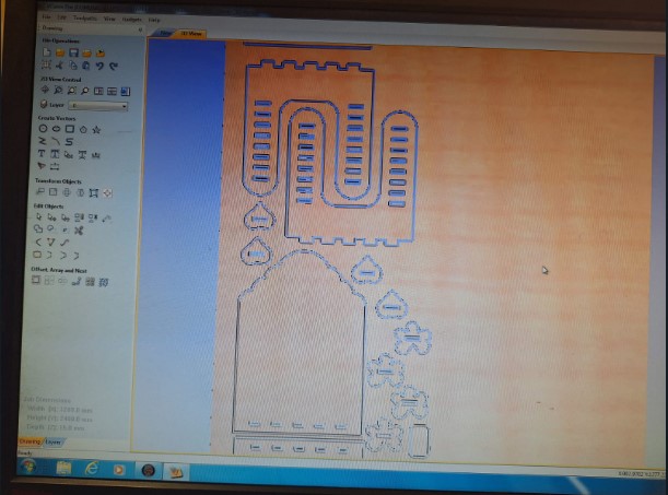
- Next, I added the dogbones to the slots. I chose to do it directly from here because that way was faster, and also I could check the diameter of the tool to have better control. To add them, I did it from the Fillet option.
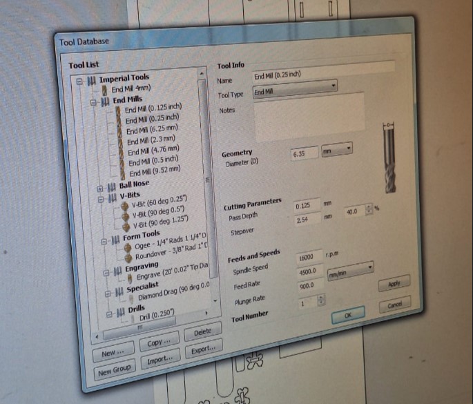
- After, I modified the tool settings. In here you can see terms such as feed rate and spindle speed (rpm) that I mentioned on the table above, but there's another very important: plunge rate. That is the speed of the mill going up and down on the z axis.
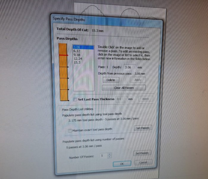
- Then I modified the pass depths, that allowed me to determine the amount of times the tool would pass depending on the material thickness and the distance the mill would cut each time. In my case there were 5 needed.
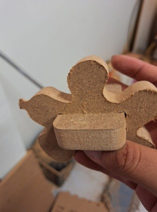
- The next step was to add some tabs to secure the piece during the cut. I tried to avoid inner corners because it would be harder to sand later. To understand them better, I pictured it as tiny hands holding the piece down. (Shotout to my local instructor Maricruz here!).
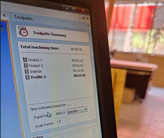
- The last thing to do was to save the cuts. I followed this order: Pockets first, then inner cuts and finally outer cuts. I didn't have any pockets, but my friend did, so we saved them first. Then the slots followed and finally the external ones. It showed a time estimate before saving.
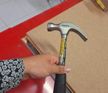
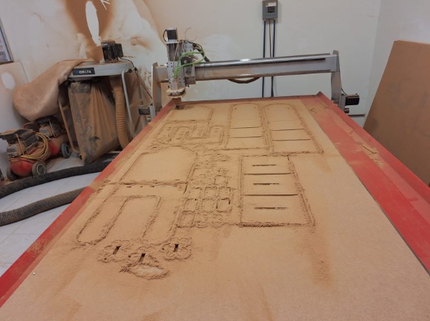
- As the time to cut was approaching, I attached the material to the bed using nails. Some routers have clamps, but mine didn't, so I used a hammer to fix it.
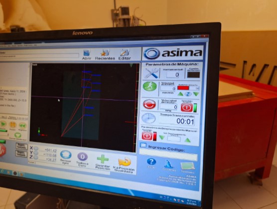
- Once everything was ready, I opened another software called AR2400.

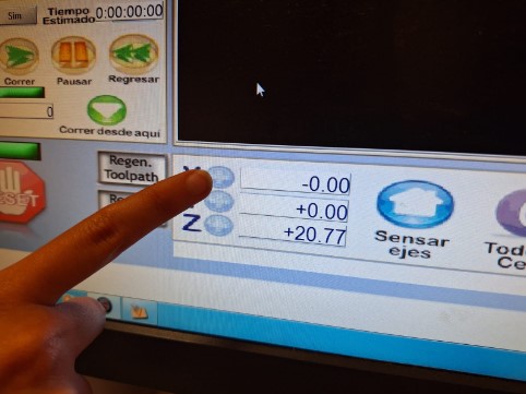
- There I could define the starting point for the cut, as well as the origin on the x,y and z axis. It's Important to avoid where the nails are, and also lower the tool slowly.
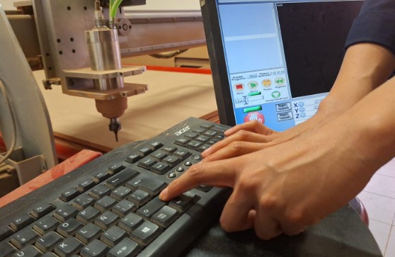
- To start machining I followed the same priority for the files as I did to save them. On the computer screen It showed me where would it begin and the shape it would cut on real time.
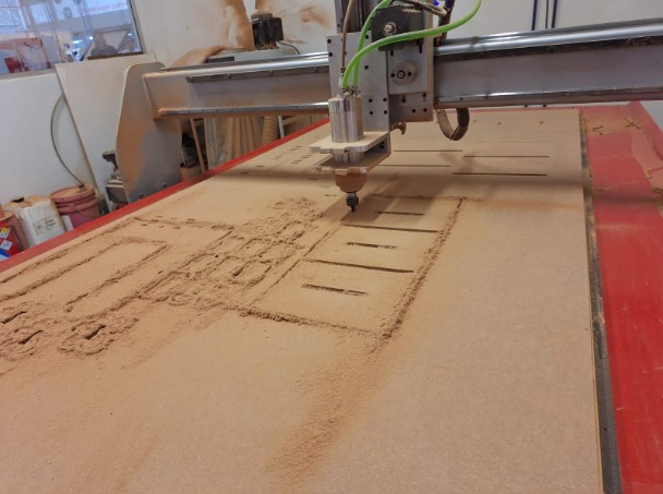
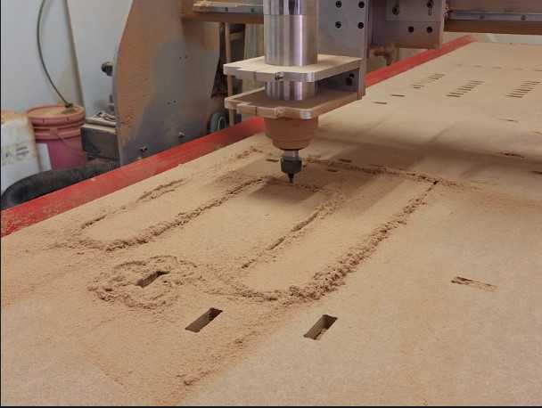
- Here you can see how it looks like when it cuts! is open.
- The cut took about an hour to finish, I vacuumed and cleaned the dust in between cuts, so there wouldn't be that much sawdust.
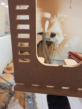
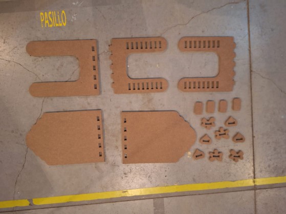
- Once the cut finished, I popped out the pieces, it was easy, but some had trouble because of the tabs, so they cot slightly damaged. The very dirst thing I did with the pieces was to check If the assembly worked, so I tested it. They fit just perfectly!
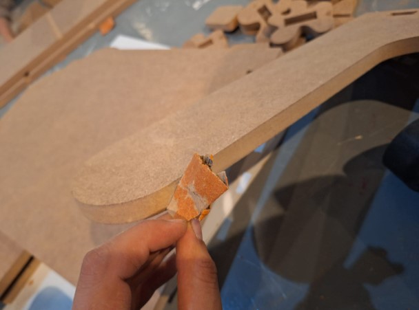
- As the tabs made the borders uneven, I sanded them using a bench sander and a regular sand paper. It was pretty easy and quick too, that's why I reccomend avoiding tabs at difficult places, it would have slowed this step.
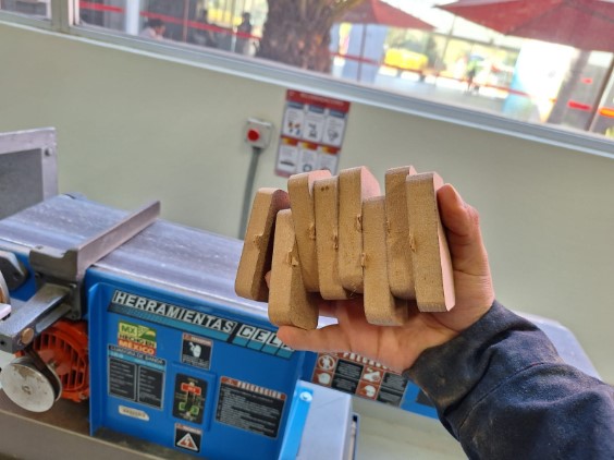
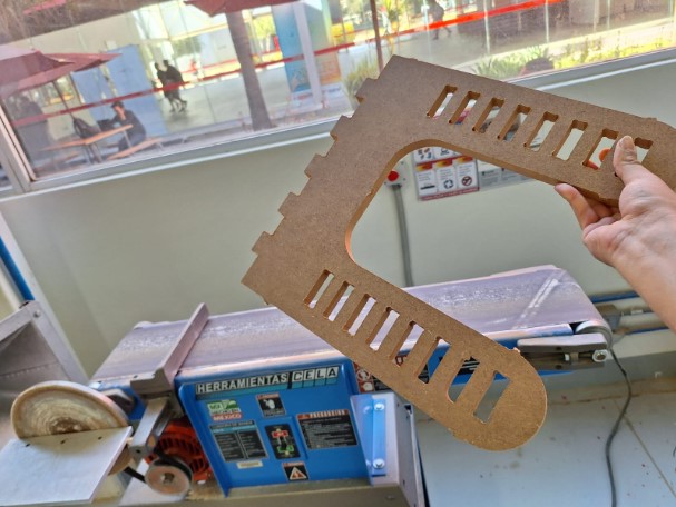
- Here are all the pieces I cut, all ready to assemble. Yo can see that I made two of the top surface, to check If I could use it as a base as well, I also cut extra "locks" with different inner measures to test the kerf, as these would be removable pieces.
- Come here and assemble with me!
Final Result!
Showing previous work 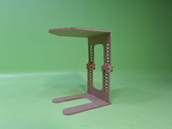
Description for Image 1
---- DXF Files ----
- Next, I opened the software to make the file for the actual cut. The software I used was V Carve Pro. It offers a free trial, so I started to preview the pieces there, but if you use it, consider that it won't let you export a file to different versions using that plan.
- Now I applied the same strategy as in the first attempt, of trying to mirror the seconf piece to the opposite side.
- To test the assembly of the parts, I exported each extrussion as a different field and used the assembly tool from SolidWorks. Here I noticed that probably the design was ok as a concept, but too much to continue, so I changed my mind again!
Attempt 2