14. Networking and Communications
During this week, we worked on sending information between two boards, so that we ould get to
understand better how is it possible to link a PCB with a mictocontroller to another one.
During our group assignment, we reviewed some methods that work for serial communication, so that
was clearer for me to make this week's practice based on that.
If you wish to check what we made and the communication method we followed, you may check our group assignment Here .
Also, If you're interested, here are some other communication protocols that exist:
Type of Communication |
Details |
|---|---|
| Parallel Communication |
Data Bus: Uses multiple lines to transmit data simultaneously. This
is fast
but requires many physical connections. Examples: PCI, ISA. |
| Serial Communication |
UART (Universal Asynchronous Receiver-Transmitter): Asynchronous
serial
data transmission. Common in RS-232 connections. SPI (Serial Peripheral Interface): High-speed synchronous communication, useful for short distances. I2C (Inter-Integrated Circuit): Synchronous serial communication, suitable for short distances between multiple devices. USB (Universal Serial Bus): Universal serial protocol used to connect various peripherals. CAN (Controller Area Network): Used in automobiles and industrial systems for communication between microcontrollers. Ethernet: High-speed network communication, common in local and wide area networks. |
| Wireless Communication |
Wi-Fi: High-speed connection through a wireless local area
network. Bluetooth: Short-range communication, useful for peripherals and personal devices. RF (Radio Frequency): Used for long-range communication without wires. |
| Optical Communication |
Fiber Optic: Uses light to transmit data at high speed and over
long
distances. Infrared: Communication through infrared signals, common in remote controls and some short-range devices. |
| Expansion Bus Communication |
PCIe (Peripheral Component Interconnect Express): High-speed bus
protocol
mainly used in computers. VMEbus (Versa Module Eurocard): Used in industrial and defense systems. CompactPCI: Compact version of the PCI bus, used in telecommunications and industrial systems. |
| Industrial Bus Communication |
Modbus: Serial communication protocol in industrial systems. Profibus: Fieldbus protocol used in industrial automation. |
Getting started
As for this week I followed the I2C protocol, which is used for short-distance communication
within a device or between multiple devices on the same bus.I had to understand better how it
works and
the implications to connect two or more boards together.
The main terms that you must know to start sending messages are the elements required to
communicate:
- Connection: SDA and SCL lines are connected to all devices on the I2C bus, often with pull-up resistors. SDA (Serial Data Line )
- Purpose: Transfers data between devices in an I2C communication.
- Function: Carries the actual data being transmitted.
- Purpose: Carries the clock signal used to synchronize the data transfer between devices.
- Function: Provides the timing signal that indicates when data can be read or written.
- Master-Slave Relationship:One device acts as the master (initiates communication), others as slaves (respond to master).
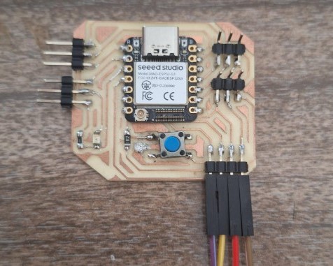
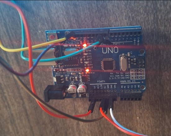
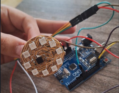
Master ESP32S3 board + Arduino Uno slave + Neopixels
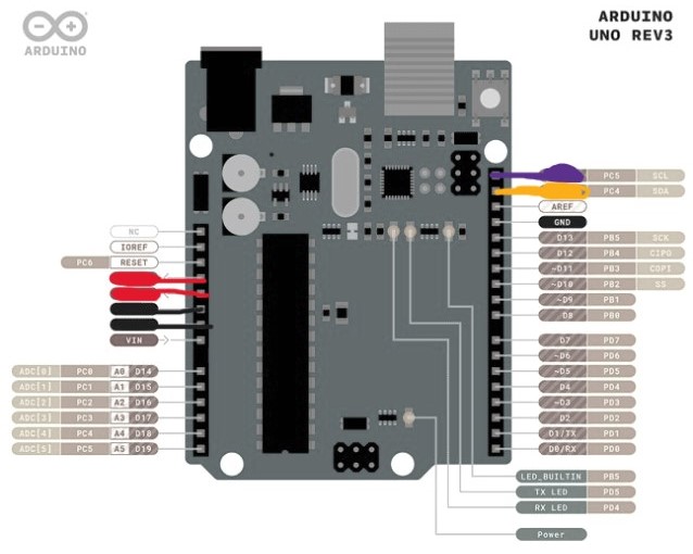
- I started reviewing the connections of the boards I would be using. I knew I needed
four
pins on each board: SDA, SCL, PWR and GND. Some advise to share GND only, as a
reference, but I chose to connect these 4. I located them in the Arduino Uno
and
"THE" Board I made for week 8 .
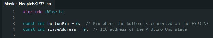
- Then, I had to start the code for the Master. I included the Wire
library to facilitate I2C communication. I defined the buttonPin as 6,
where the button is connected, and set the slaveAddress to 9, which is the I2C
address of the Arduino Uno slave.
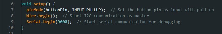
- To initialize the setup , I configured the buttonPin as an input with a
pull-up resistor to ensure stable readings. I started the I2C communication as
the master using Wire.begin(). Additionally, I initialized serial communication
at 9600 baud rate for debugging purposes.
-
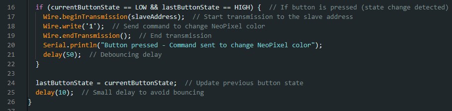
In the main loop, I checked the state of the button connected to buttonPin
using digitalRead(). When the button was pressed (detected by its state changing
from HIGH to LOW), I initiated transmission to the slave device at slaveAddress using
Wire.beginTransmission().
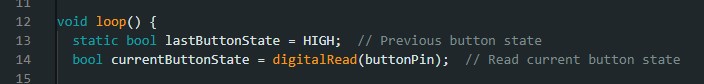
-
I then sent a command ('1') to instruct the slave to
change the NeoPixel color with Wire.write(). After sending the command, I ended
the transmission using Wire.endTransmission(), updated the previous button state,
and included a small delay to handle button bounce.
- Next thing I did was to upload this code to the board I would use as my master. I recommend to send it before wiring anything together. Now It was time to code the Slave.
-
Int the code for the slave, I started b
including both: the Wire library for the communication and the Adafruit
NeoPixel
library to control the NeoPixels. Also, defined the pin I would connect the neopixels to
in the Arduino, this was 9 , and set NUM_PIXELS to as these are the ones
I have in my board.

-
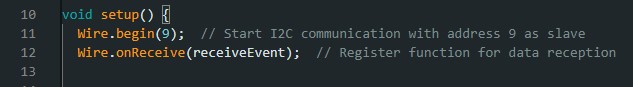
During setup, I initialized the Wire library to begin I2C communication,
setting the Arduino Uno's address as 9 to act as the slave device, keeping the
same I had on the master code.
I registered a callback function (receiveEvent) to handle incoming I2C data.
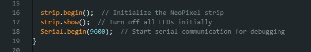
-
Additionally, I initialized the NeoPixel strip using strip.begin() and turned off
all LEDs by calling strip.show(). Serial communication was started at 9600 baud
rate for debugging purposes.
- Then I used the receiveEvent function for whenever data was received from the master.
Within this function, I read the command sent by the master. If the command
received was '1', I executed a sequence to change the color of all NeoPixels.
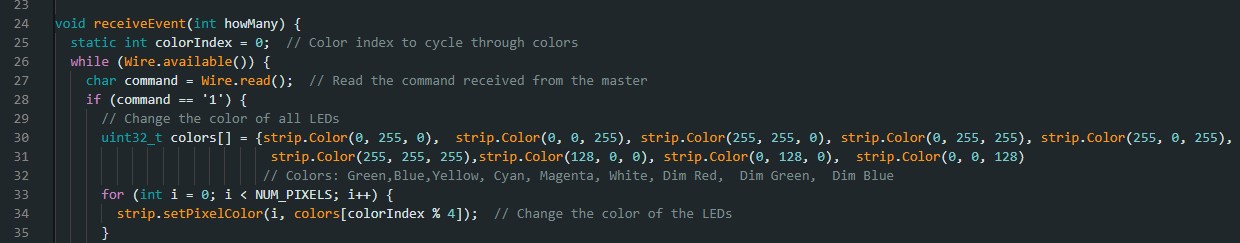
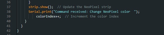
- Finally, I updated the NeoPixel strip with new colors based on a predefined
array of colors, then displayed these colors using strip.show().
- Then, as I did with the master, I uploaded this code on the arduino as the slave. Now it was time to wire everything!
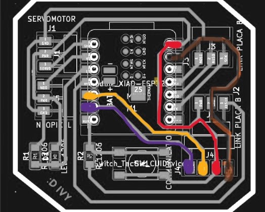
- I wired the connections on my master board, and used the same colors as in the first
diagram to avoid mistakes, then I connected it to the Arduino and I connected the Neopixel
board to the arduino as well.
- Then connected my master board to Power and pressed a button. It worked! Note: As
you
can see the LED on my board no longer works, if you connect something to another device
make sure to use the right V+ and also use color coding for each wire, I accidentally
burned mine :(.
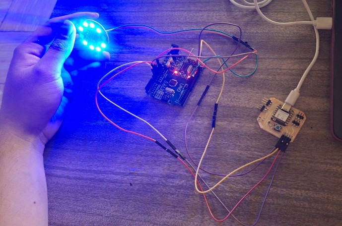
- Look at the color change! I put my resin cap on top to distribute the light better. This is
the final result!
---- Files ----