10. Mechanical Design / Machine Design
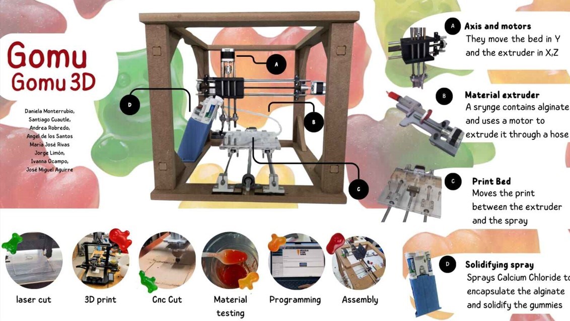
This week was all about teamwork, since the assignment consisted from choosing a machine to actually build it. We had a team of 8 people, and our majors were from engineering to design and marketing, so, to decide what we were going to make, we chose something fun. That's how we came up with the idea of a gummy printer. You can see the final result Here
The planning
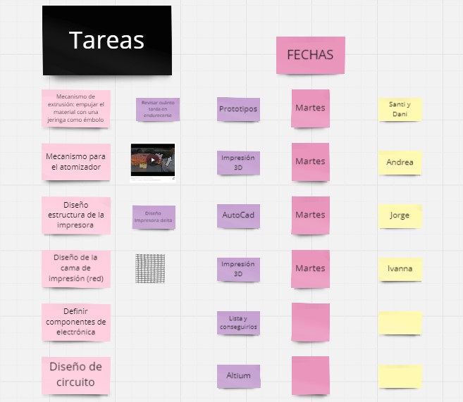
To make things work we decided to develop a plan in advance. We can say, the stages of the project planning where three: the definition, the scheduling and the distribution of tasks among the team.
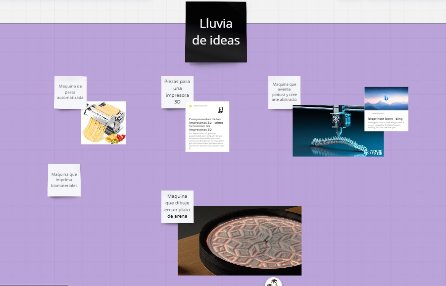
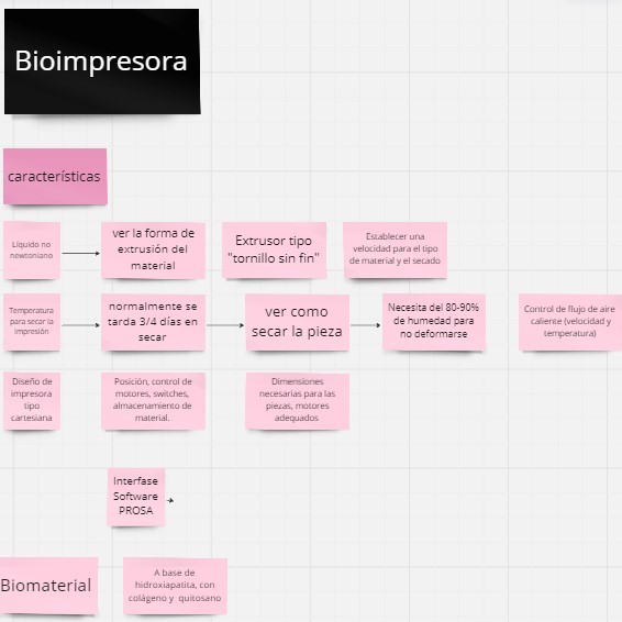
- To define the project, we shared a board on the Miro platform, so we all could write and
see everything at the same time. There, we started with a brainstorming session to give ideas
and at this point we chose our first option: A 3D printer for a Biomaterial.
- Once we knew we wanted to create a Biomaterial printer, we had to choose the one to print. At
first, one of our teammates had a project already with a material based on hydroxyapatite, with
collagen and chitosan that could be used to build bones. This was a material which she already
had experimented with and wasn't that expensive to get, so we chose it. It's consistency was
similar to toothpaste and could be considered a non-newtonian fluid.
That was the first chalenge.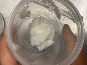
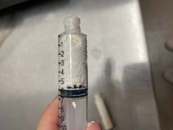
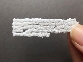
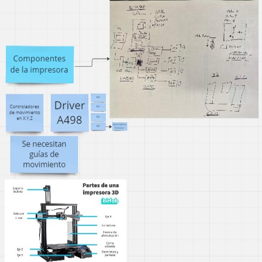
- Then, we started reviewing the requirements to build the machine. We had to consider the mechanical pieces, the software to use and test how we would treat the material, because it was difficult to extrude and had to dry a little between layers.
- The more we started to research about the material and ways to treat it as an non-newtonian fluid, we noticed that this could be more complex. Also, we didn't find as many references on other printers that could work on this material so, considering the time we had to finish, we thought wiser to change the mateiral. Here is when we decided to go from one biomaterial to another, now making a printer for gummies that used alginate and calcium chloride.
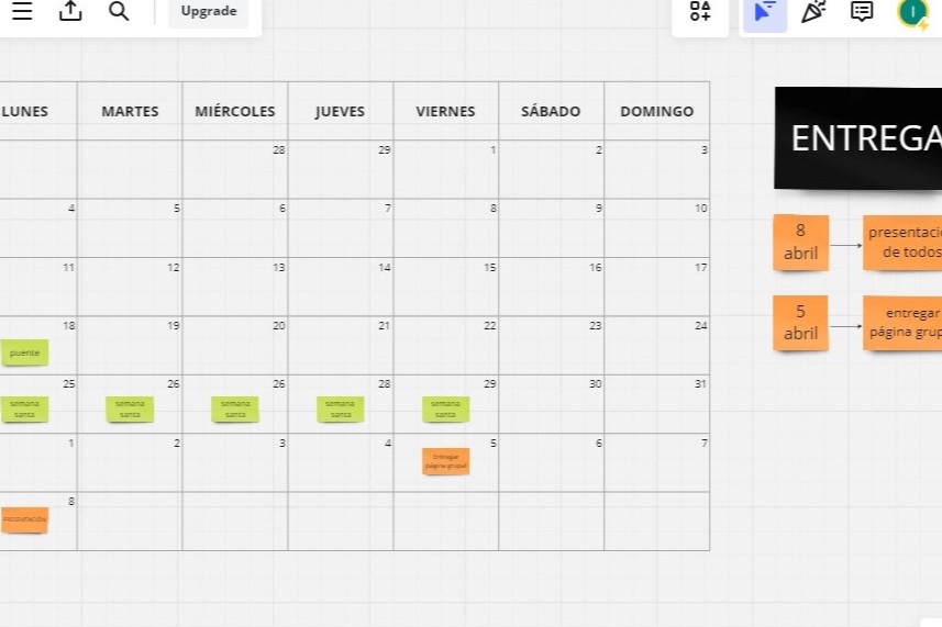
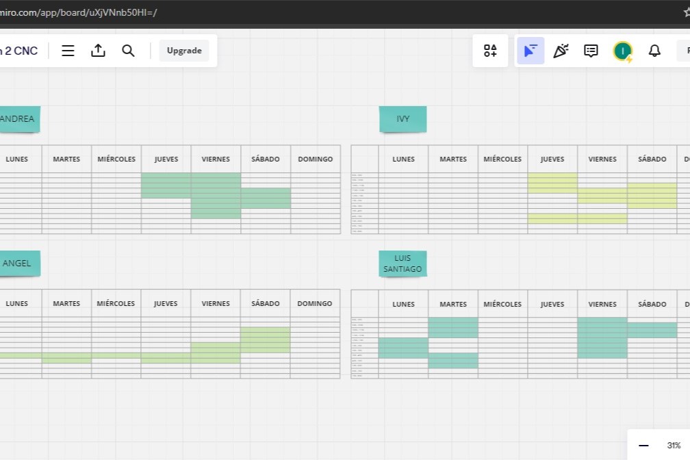
- The next step was to elaborate the working schedule. To do this we added a calendar where we marked the day we would present the machine and set time goals based on this, for the group and individual pages. Also, we considered the free time each of us had to work on the project and we shared our own schedules to define the moments where we could gather and work together.
- Now, for the final stage of the planning, we divided some of the basic tasks among the teammates. I got assigned some 3D design and printing, so that's what I did.
What did I do?
I knew that my role could be more valuable designing pieces for the machine and helping to assemble the mechanical parts, so basically my work consisted in this. I can divide my work in three: Making the prototype for the first structure, making the printing bed and assembling the main machine. To do my part I also measured different standard pieces as screws, rails and bearings.
Making the bed
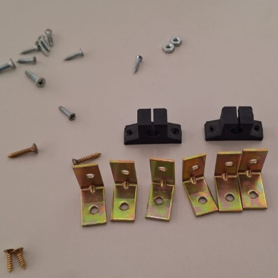
- Before drawing the printing bed of the CNC, I took reference from another CNC that had
been made previously at my FAB. Since we also reused some metallic pieces, it was really helpful
to take the pieces with me and use a Vernier caliper to measure things better. Here I
saw that the bed should have a flat surface and pieces to attach the bearings too.
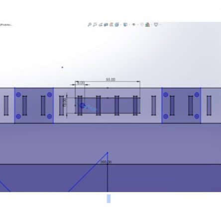
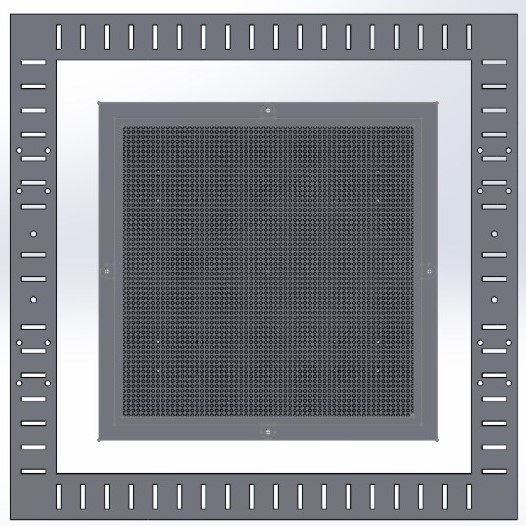
- Taking this into consideration, I made the piece drawing using SolidWorks. The idea was to make
three layers for the bed: the
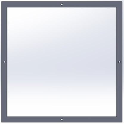
main bed, a frame and the lower piece that would have the bearings atached. It's important to
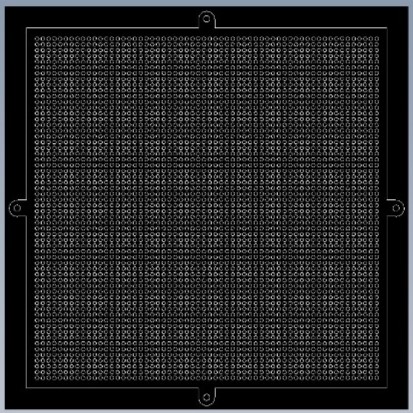
say that the main bed was thought to be holey, since our material required to be sprayed to dry,
and we didn't want any puddle forming, so the hollow's would allow it to drain.
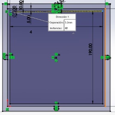
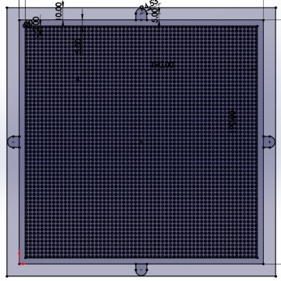
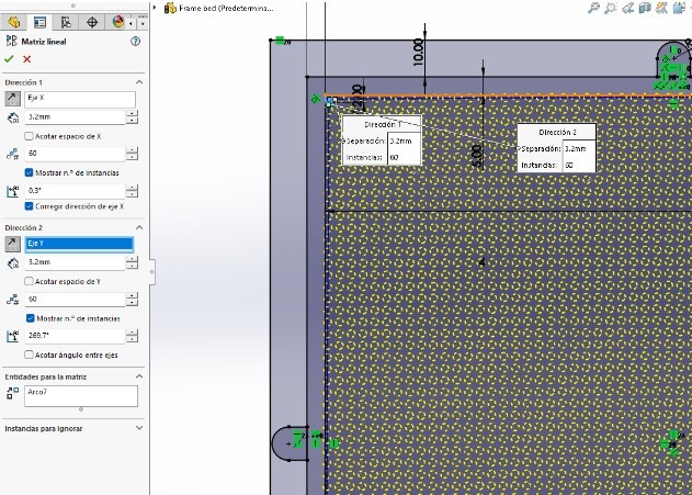
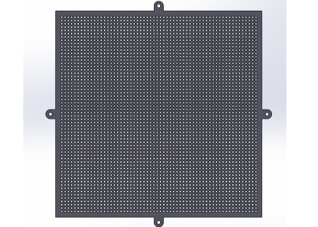
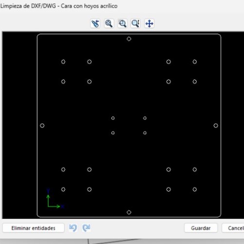
- As I made this three basic pieces, they would be one over the other and conect with screws. First I made the piece for the holey bed , which was pretty simple: From a base circle with a small diameter, I made a matrix of circles for the perforations. Even as It seemed simple, the program had some toruble to render that many holes so, I advice being patient.
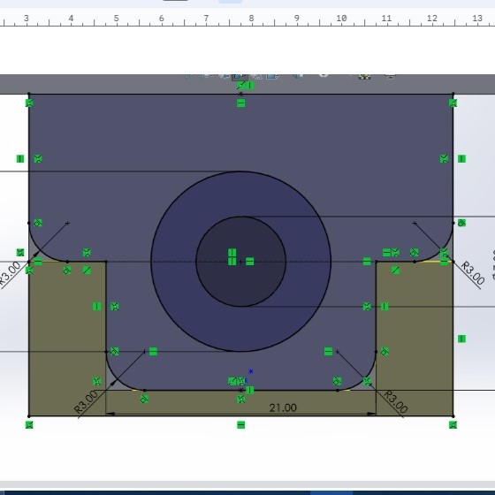
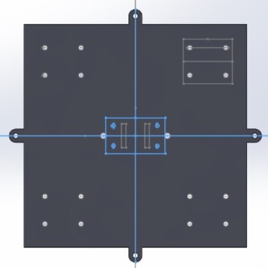
- Then, I made the lower piece, that had to be the last layer of the bed, so the design had to include an attachment part where the bearings would embed. To do it, I added another sketch that was perpendicular to the main bed and built it. It's improtant to say that the main pieces of the bed were going to be cut with the laser cut, and the bearings part was made for 3D printing.
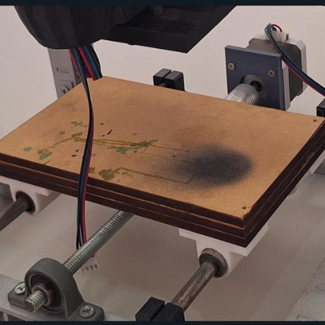
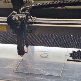
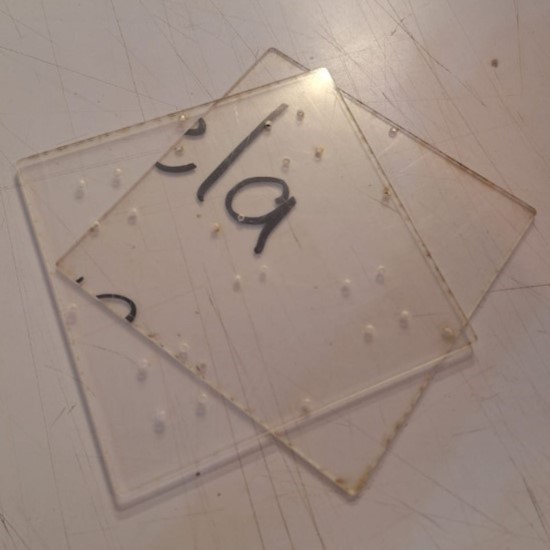
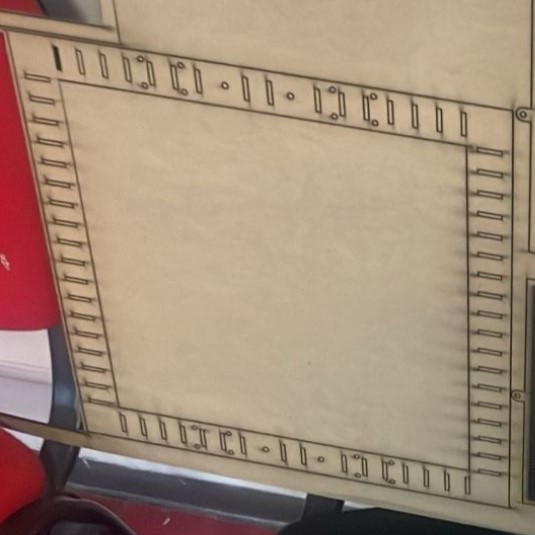
- Then I saved the files on a DXF format. These 3 layers got cut in MDF using the laser cut and we ran the first tests with the material over it.
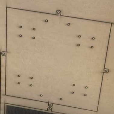
- After these first tests, we noticed that MDF may not be the best material to print over, as it got wet and could develop mold. That, because between layers we needed the spray and the material was a little sticky anyways by itself. Also, we saw that neither the holey surface and all three pieces were truly necessary for the printing bed if we changed the material, so I simplified the design to only two pieces and exported it again.

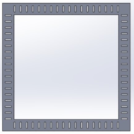
- In the end, this second design was more practical and I only had to cut it once in the Laser cut. It reduced to two pieces: the actual bed where the machine would extrude and a twin piece that went underneath, but with holes to attach the bearings directly using screws.
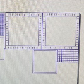
Prototyping the structure
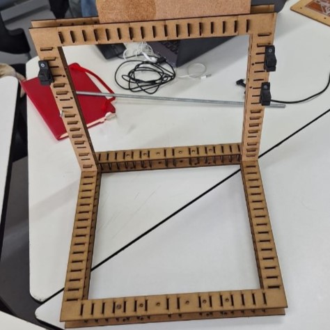
- As I did the bed, I also ofered to make the structure and preview it on SolidWors, so I could verify things such as the Kerf, and the amount of pieces needed to make the structure stable.
- To make it, I took the bed dimensions as a reference and also measured the size of the rails as
a
parameter for the maximum size to the sides. The structure had a simple design: two pairs of
frames
linked by
MDF squares to add volume. There I also made the holes for the screws to attach the rails,
motors
and supports.
- A part of the team helped me to assemble and cut all of this during the Holy Week break. Santiago, Daniela and I tried to modify a little the design after some Kerf tests, but in the end it didn't have enough stability to resist the vibrations the motors would provide, so we gave up the idea of using 3mm MDF and decided to use 15 mm. Instead, this worked as a prototype to verify the position of everything and became more like a reference model.
Other contributions
- I also helped to assemble once we had the pieces, and worked side to side with the team to solve problems with tools or securing the motors.Other role I had was making the final slide and helping record the video.
- Choose and define roles
As we started the first week trying to offer something to the team, we were not as productive as the last week, when everyone had at least an assigned task based on their skills. About this matter, I highly recommend to have a session to define roles and skills each one has and also build a team dynamic. I think it's not necessary to have a single team leader, but it could have been very helpful to have someone as project coordinator, in order to keep track of progress and deadlines. - Inspire from others but know your limits
Our project got a lot of information and references from other CNC printing machines, and despite all the information we got from there, there was a moment where we had to stop thinking about the potential of what we could make and be more realistic. This gave us a delay in action, since we got too focused in printing the first material and the wonder it would be to make it possible. In the end, we had to consider timing and resources, so I recommend to escalate the project from the references you find and be conscious that you will have to actually make it, so be aware of your skills! - Choose systems not single materials
Another thing that could have been made differently was the material planning, because we started thinking about the ones with the easier or quicker production processes. As the project kept going, we realized that the materials worked good enough separately, but once we integrated them in a single product there were some problems.
An example is the vibration of the motors on the first version of the structure that we didn't think about; or the material choice for the printing bed; that was originally thought to be made of MDF and didn't consider humidity nor porosity of the printing material. - Don't wait too much to start programming
We payed too much attention to the mechanical design, since that was what most of us had experience with, but as the deadline approached and we started making our codes and tests there were some problems related to the movement that we could have prevented if we had tried it as soon we got the pieces. My recommendation is to start trying to move the mobile pieces as soon as you havethem, so you can fix any mistakes beforehand and avoid solving problems in a rush. - Modify the position of axis and motors
The machine is functional as it is, but the printing area was limited to only one quadrant because of the axis position, so even with our bed moving at it's maximum in Y, we didn't exploit it's full potential due to the place where the X and Z was fixed. It would work better if these were at the middle of the machine instead to one side. - Simplify the code
In our machine, I would simplify the code to move the motors, since we had to control each separately. Also, I would choose a different interface to control the motors from the computer, because ours was not as stable as we wished it to be. - Consider alimentary standards
As we designed the machine, we kept in mind the goal to print a biomaterial that could be edible, but we are aware some of the conditions of printing make it hard to keep it food safe. Things like the material storage and possible decomposition after a while make it necessary for us to consider parameters to keep the machine food safe always, considering that factors as heat and air on the environment can accelerate some process that are undesirable for gummies or edibles in general. - Make the nozzle more precise
We used a syringe and a thin tube as our nozzle, but if we wanted to make smaller designs, modify the wall thicknes on higher pieces or play with different consistencies of extrussion it could be ideal to test different sizes and materials for our nozzle.
Improvement opportunities to our process
As we finished the machine, there were some steps where we could have made it better. Some of these started from the planning and definition, so here are some of my suggestions to reach a better result:
Improvement opportunities to our machine
---- Files ----
- A part of the team helped me to assemble and cut all of this during the Holy Week break. Santiago, Daniela and I tried to modify a little the design after some Kerf tests, but in the end it didn't have enough stability to resist the vibrations the motors would provide, so we gave up the idea of using 3mm MDF and decided to use 15 mm. Instead, this worked as a prototype to verify the position of everything and became more like a reference model.
- As I made this three basic pieces, they would be one over the other and conect with screws. First I made the piece for the holey bed , which was pretty simple: From a base circle with a small diameter, I made a matrix of circles for the perforations. Even as It seemed simple, the program had some toruble to render that many holes so, I advice being patient.
- Then, we started reviewing the requirements to build the machine. We had to consider the mechanical pieces, the software to use and test how we would treat the material, because it was difficult to extrude and had to dry a little between layers.