
10. Machine Design
For this week´s project, we are designing a CNC machine of our choice in a group team. Our team is formed by: Daniela Monterrubio, Santiago Cuautle, Joé Miguel Aguirre, Ivanna Ocampo, Andrea Robredo Cernicchiaro, María José Rivas Arreola and Jorge Limón Baldearas
For the group assignment, we have:
- Design a machine that includes mechanism + actuation + automation + application
- Build the mechanical parts and operate it manually
- Document the group project

3D Printer
We decided that our machine will be a 3D printer that extrudes an edible alginate, that cures by spraying a calcium chloride solution over it. Since some of our teammates already did worked with This substance, we thought it would be interesting to build something out of this material.
Bill of Materials (BOM)
Quantity |
Component |
|---|---|
| 1 | Arduino UNO |
| 1 | CNC shield |
| - | 15 mm MDF |
| - | 3 mm acrylic |
| - | PLA filament |
| 1 | 3D printed spray mechanism |
| 4 | 3D printed guide shafts |
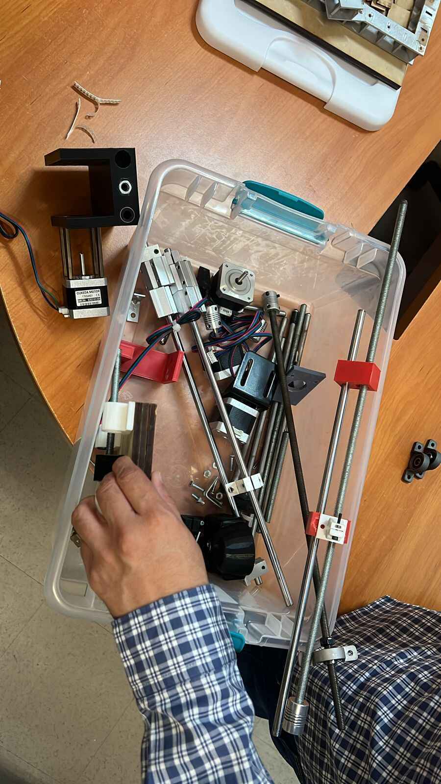
| 6 | Guide shafts |
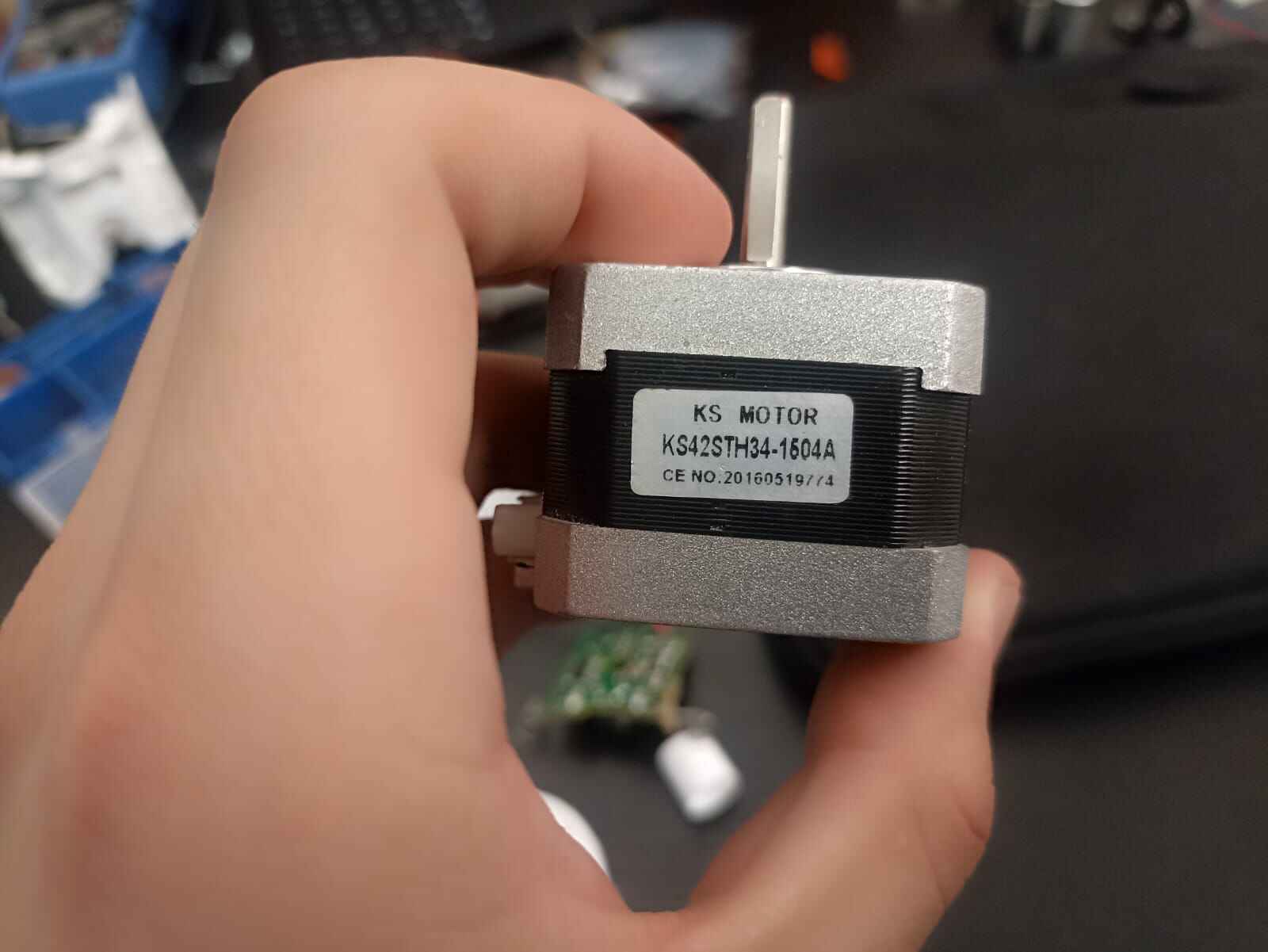
| 4 | Stepper motors |
| 4 | Sc8uu linear bearings |
| 6 | 8 mm chrome rod guide |
| 4 | Flexible coupling nema 5*8 mm |
| 4 | Acme screw spindle |
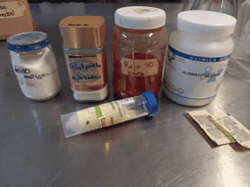
Extrusion material:
Quantity |
Ingredient |
|---|---|
| 1 pinch | Malic acid |
| 1/2 tablespoon | Monosodium glutamate |
| 0.03g | Allura Red 40 |
| 5g | Sodium alginate |
| 1 tablespoon | Tutti frutti flavoring |
| 4g | Sugar |
| 100ml | Water |
Alginate
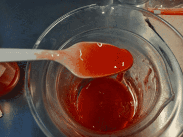
This is an example of the material being extruded with a syringe:
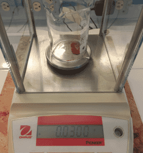
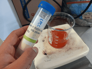
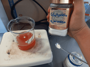
To formulate the extrusion material for the food printer. We decided to use a sodium alginate mixture because it's a versatile material for adding flavor, and its texture when mixed with calcium chloride is gelatinous, which would allow us to make candies like gummies. So for experiment 3, we decided to go all out. We used the following ingredients: A pinch of malic acid Half tablespoon monosodium glutamate 0.03g Allura Red 40 5g Sodium alginate 1 tablespoon tutti frutti flavoring 4g sugar. 100ml water
The NOM states that for Red 40 dye, it's 300mg per liter of water, but we were only going to use 100 ml of water, so we did a proportion (0.03g) and weighed it on an analytical balance.
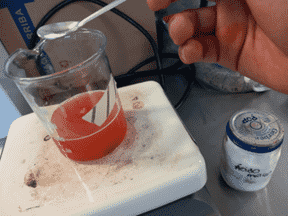
To stir, we used a stirring hotplate and a magnetic stir bar so we wouldn't have to stir constantly haha, we set the hotplate to 240 rpm.
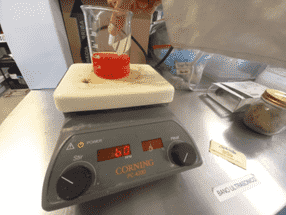
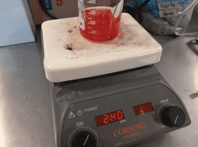
After that, we added sugar to the water, a tablespoon of flavoring (NOM Classification: Good Manufacturing Practices),

half a tablespoon of monosodium glutamate (NOM Classification: Good Manufacturing Practices), and a pinch of malic acid (NOM Classification: Good Manufacturing Practices), the latter intensifies sweet flavors, the opposite of citric acid.
We ended up with an excellent mixture. We let several university friends try a drop of our mixture, and they confirmed, as we did, that now the mixture tasted good.
Organization
We started off by discussing the principles and structure of our printer, the pro´s and con´s of each design and feature we could add to overcome the challenges our machine had to accomplish. We had to plan the design with the idea that the extrusion bed needed to function with a liquid being constantly sprayed on the surface, and what implications would that create on our printer. This took more planning in the future, but we wanted to settle a base on how the rough model of our printer would look like.
Then, we delegated individual tasks to divide the workload according to the list of small steps we needed to accomplish to get the project going:

Our instructors gave us spare parts that we would use in our printer, like stepper motors, endless scews, assembly parts and more. Of course we would need to design and build our own specific parts, but that would cover our bases.
Liquid solution sprayer
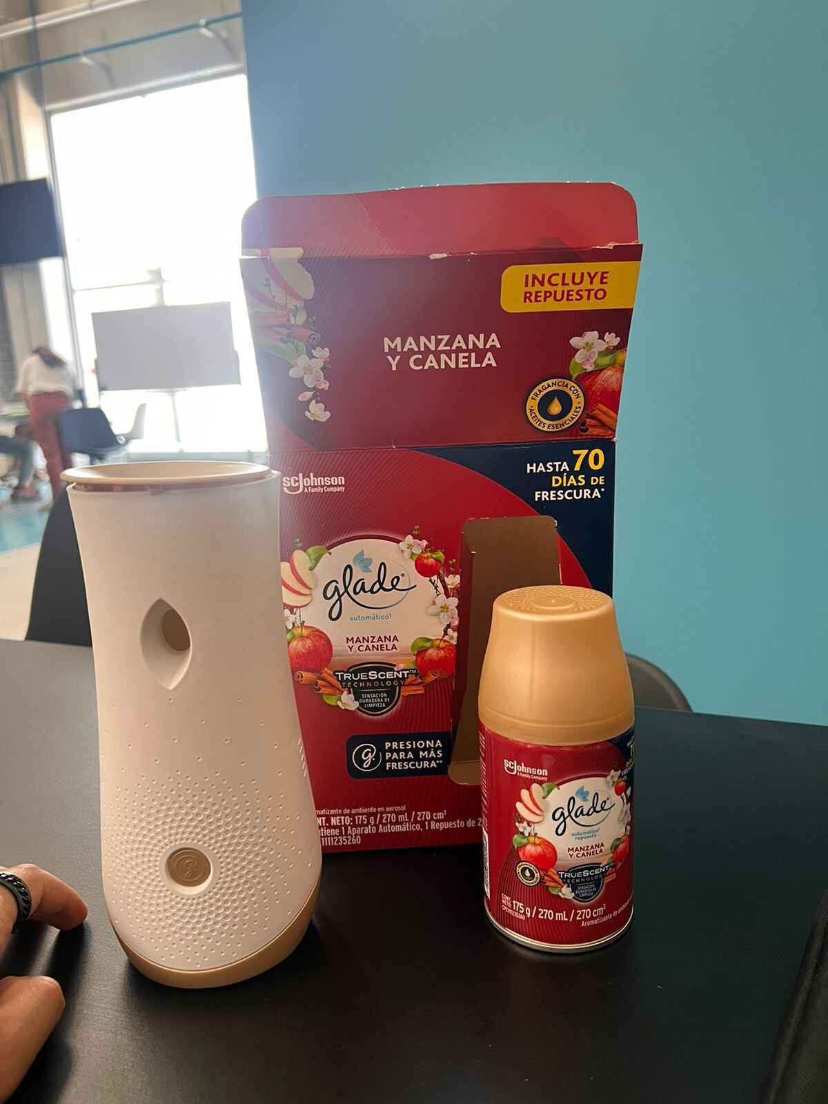
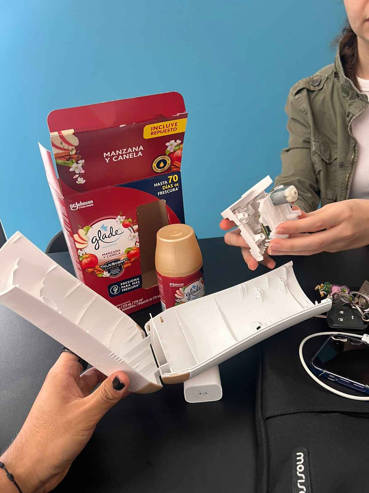
A big part of this project is spraying the liquid solution into the extruded piece at will, so we decided to take inspiration in a automatic spray air freshener, and how we could use the mechanism to control the spraying of the solution

So we bought one to pry open and check how the mechanism worked and how we needed to modify it so we could build our own.
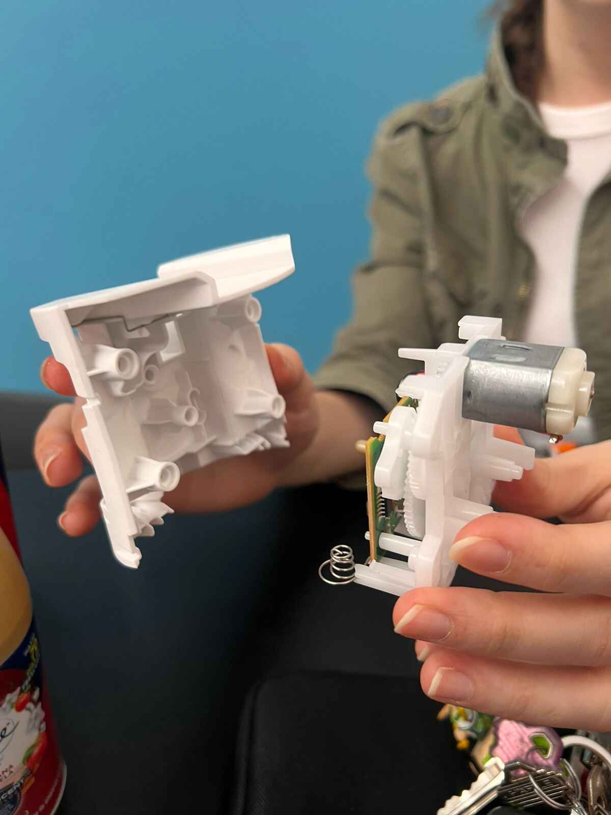
This is the mechanism working:
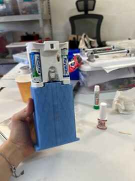
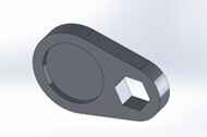
The is the bottle we try to use to spray our solution on the printer, we need to adapt the spraying nozzle to fit the pushing mechanism
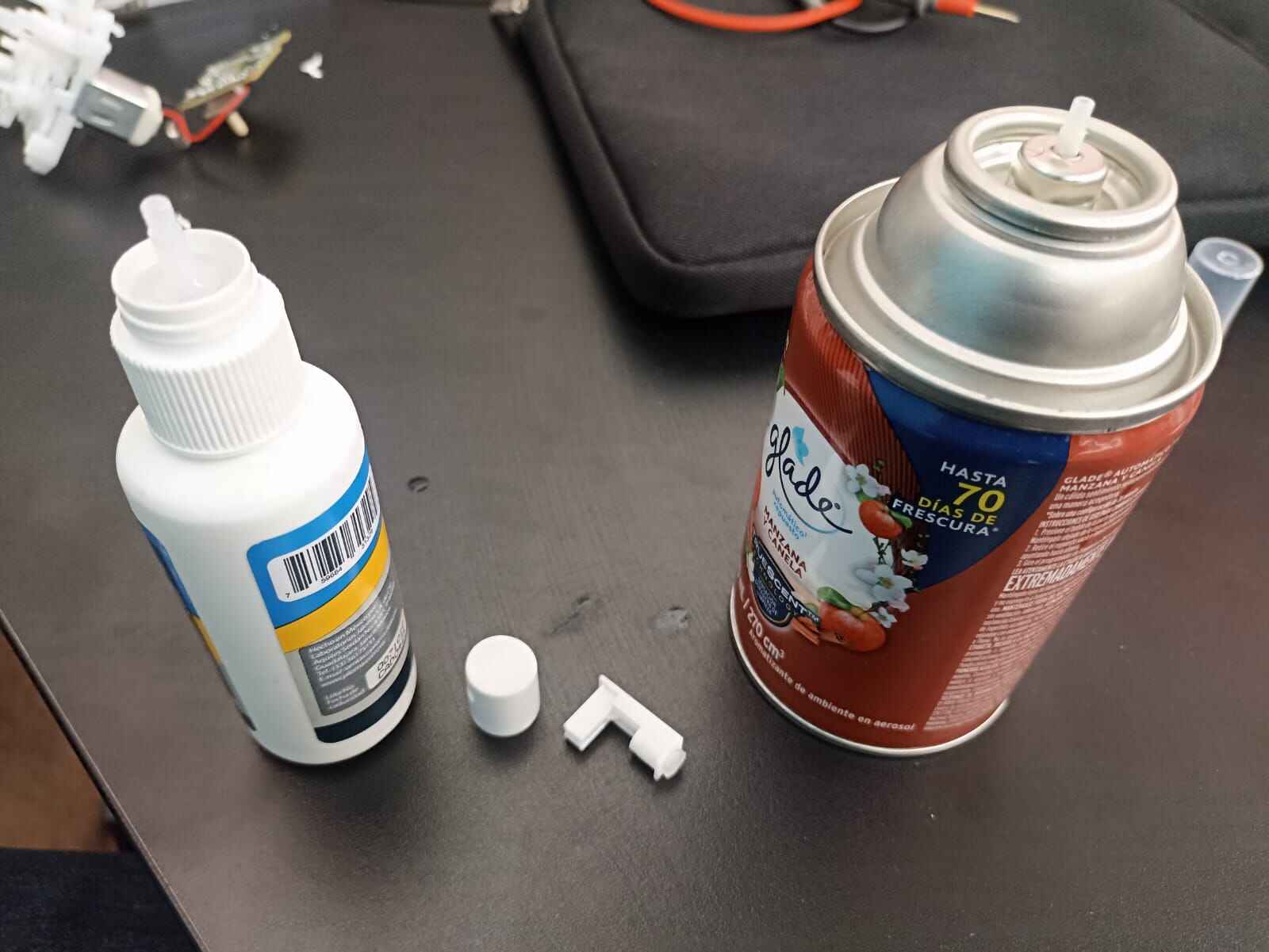
To begin the dimensions of the spray bottle were taken with a vernier and 3D modeled
Then, to replicate the piece used in the spray mechanism, we began by meticulously measuring each part and then modeling it in Rhino. Precision was crucial as the measurements needed to be extremely accurate for it to function properly. To be honest, re-designing this piece was a bit challenging.

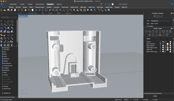
In the final step, the base piece was designed by incorporating a 25˚ angle. To achieve this, we applied a 'Boolean Difference' operation between the rectangular shape and the spray bottle, resulting in the desired outcome. Additionally, a 1mm offset was implemented on the spray bottle to accommodate any potential shrinkage during the 3D printing process, ensuring a proper fit for the bottle.
We ended up going with a 3D printed fitted version of the mechanism to spray the liquid solution

When these were finally done, we assembled the pieces of the spray mechanism.

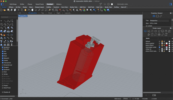
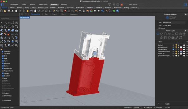
Structure
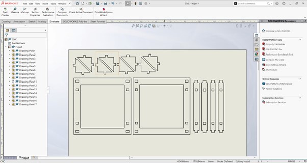
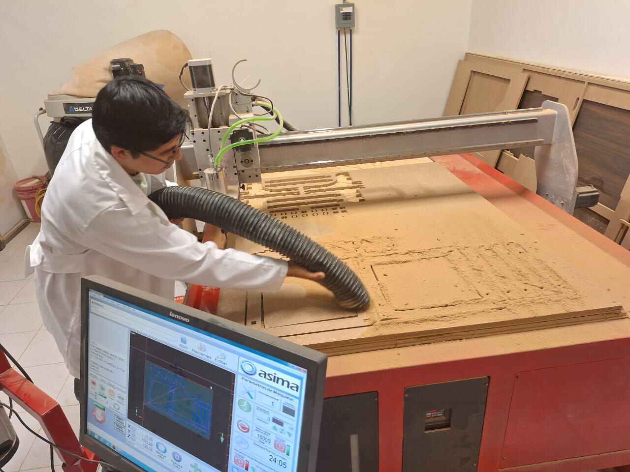
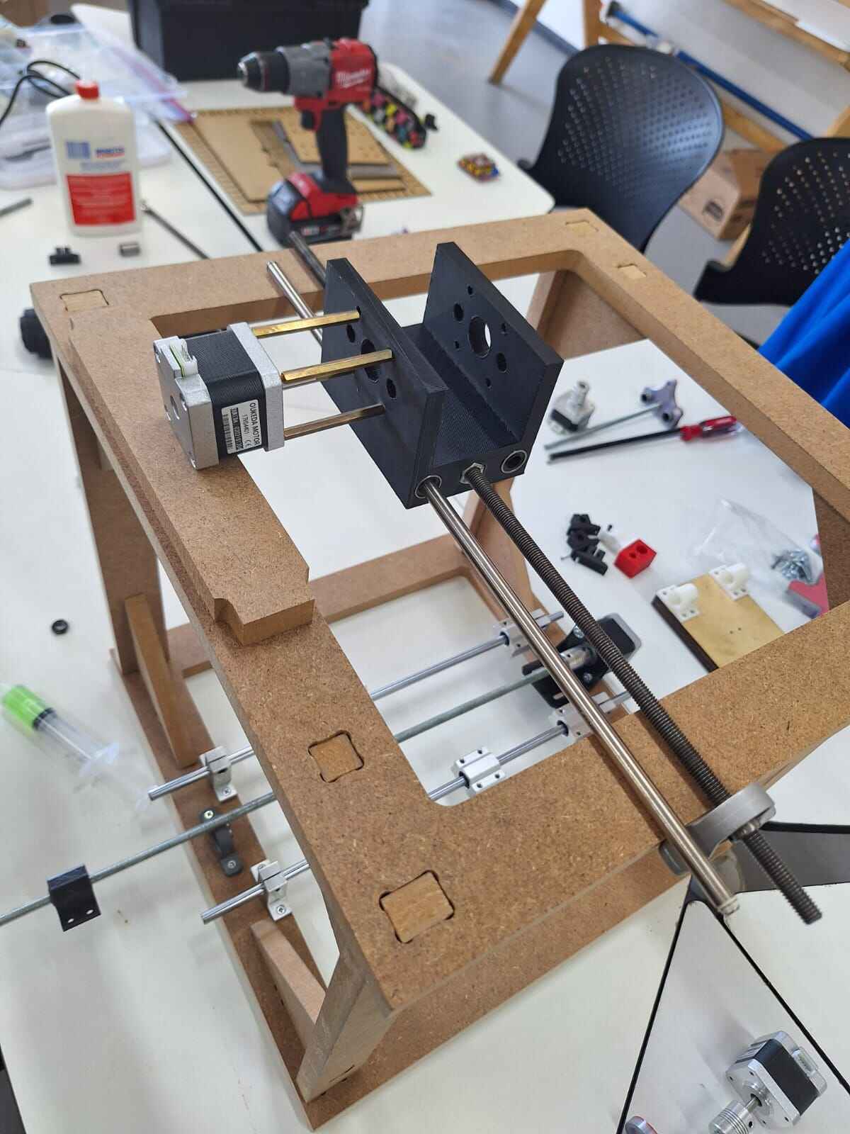
There were some references to 3D printers built at the university by the engineering students, during their first semesters. Most of them had a similar structure, which consisted of MDF frames for the X and Y axis linked by smaller pieces of wood, so that was the inspiration for our first prototype. As we already had some mechanical pieces such as linear bearings and metal rails, the design included holes for the screws in the desired position.
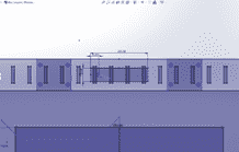
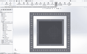
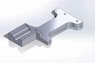
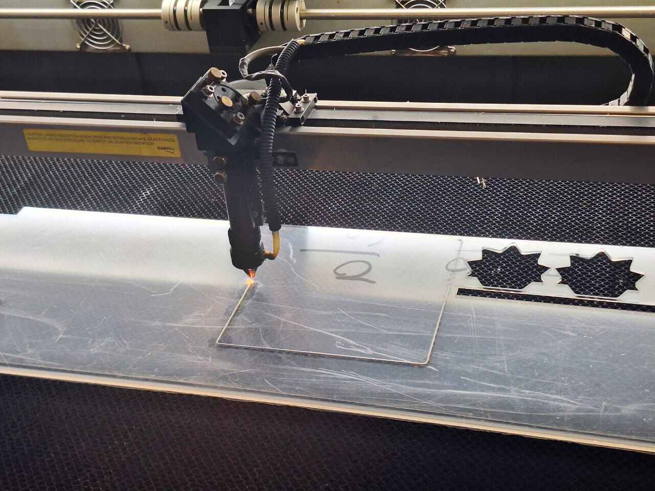
To design this first structure, we used solid works, so that we could verify the assembly as we added pieces. Basically we made three different parts for the main frame: The vertical structure, horizontal structure and the link pieces. This was also what we cut first using the laser machine, but we made different tests to verify the kerf and fit of all pieces. We also prototyped the print bed, this consisted in a three-piece structure that had: a fully holed surface, a frame and a piece that linked to the bearings. This was supposed to be printed, but as the main piece had too many holes, we cut all of it using the laser cut as well. :

We had the assembly and component overlay done so we could verify the measurements of the pieces given and the pieces created.

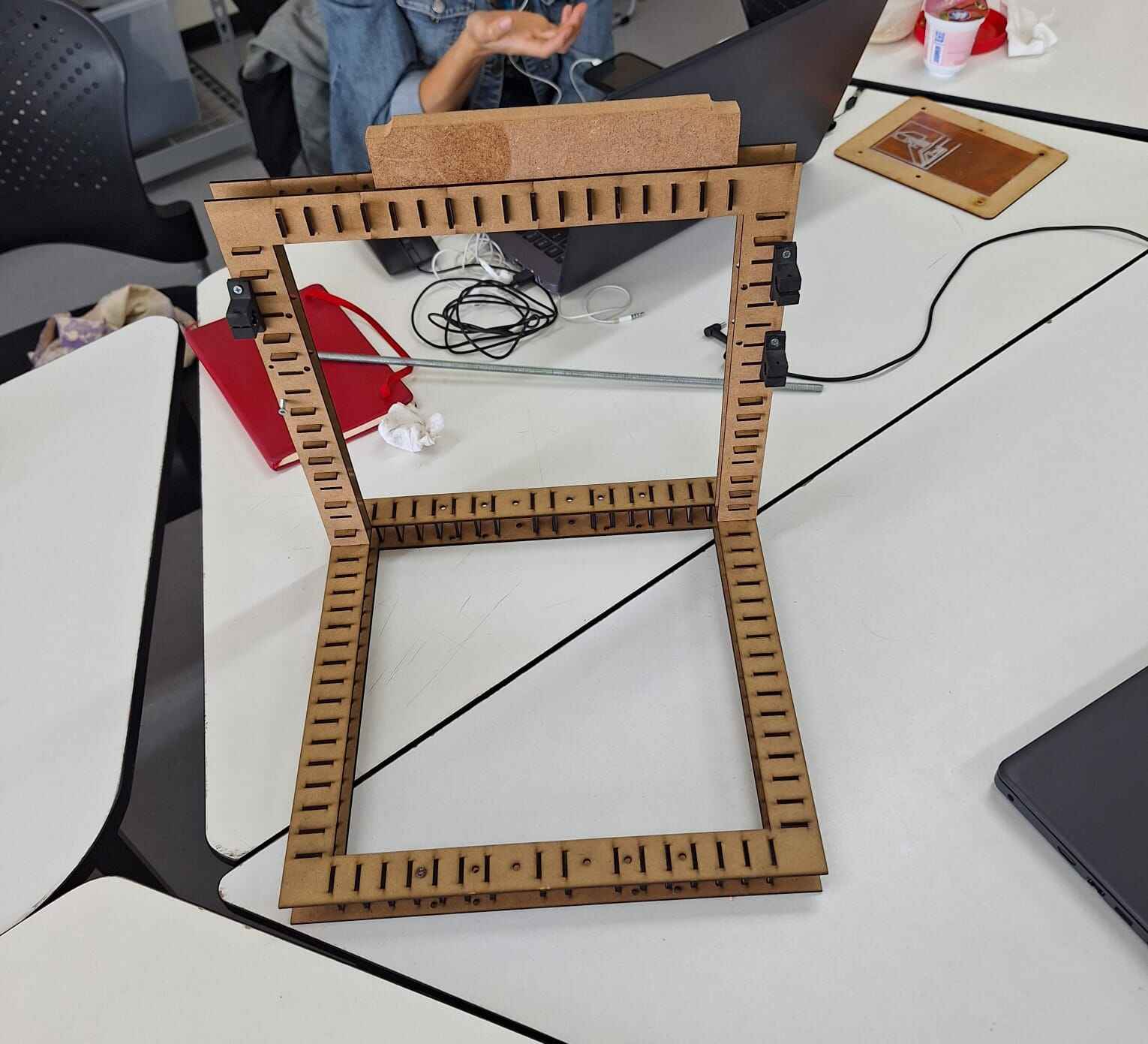
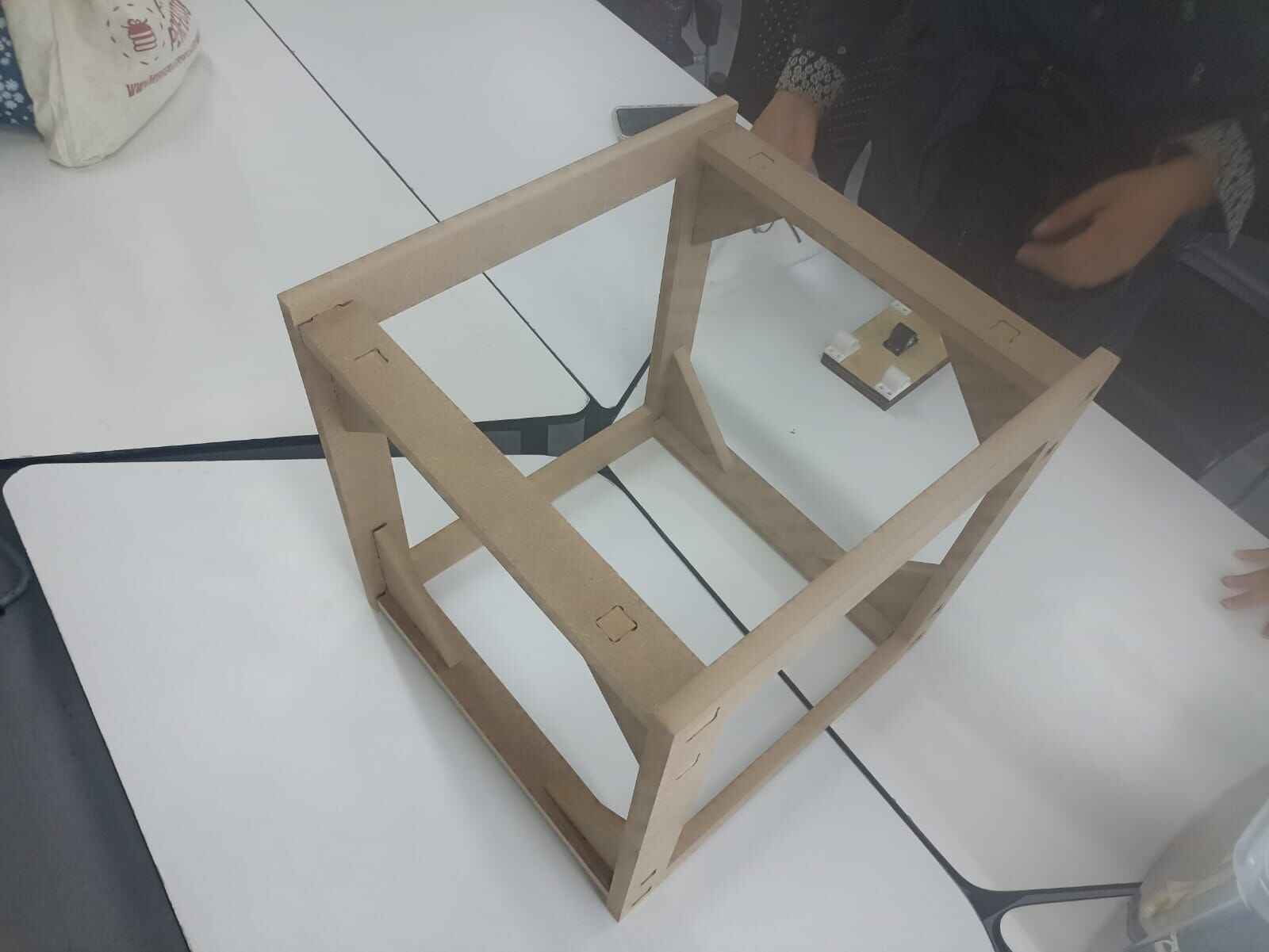
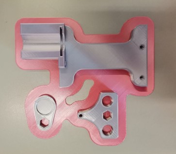
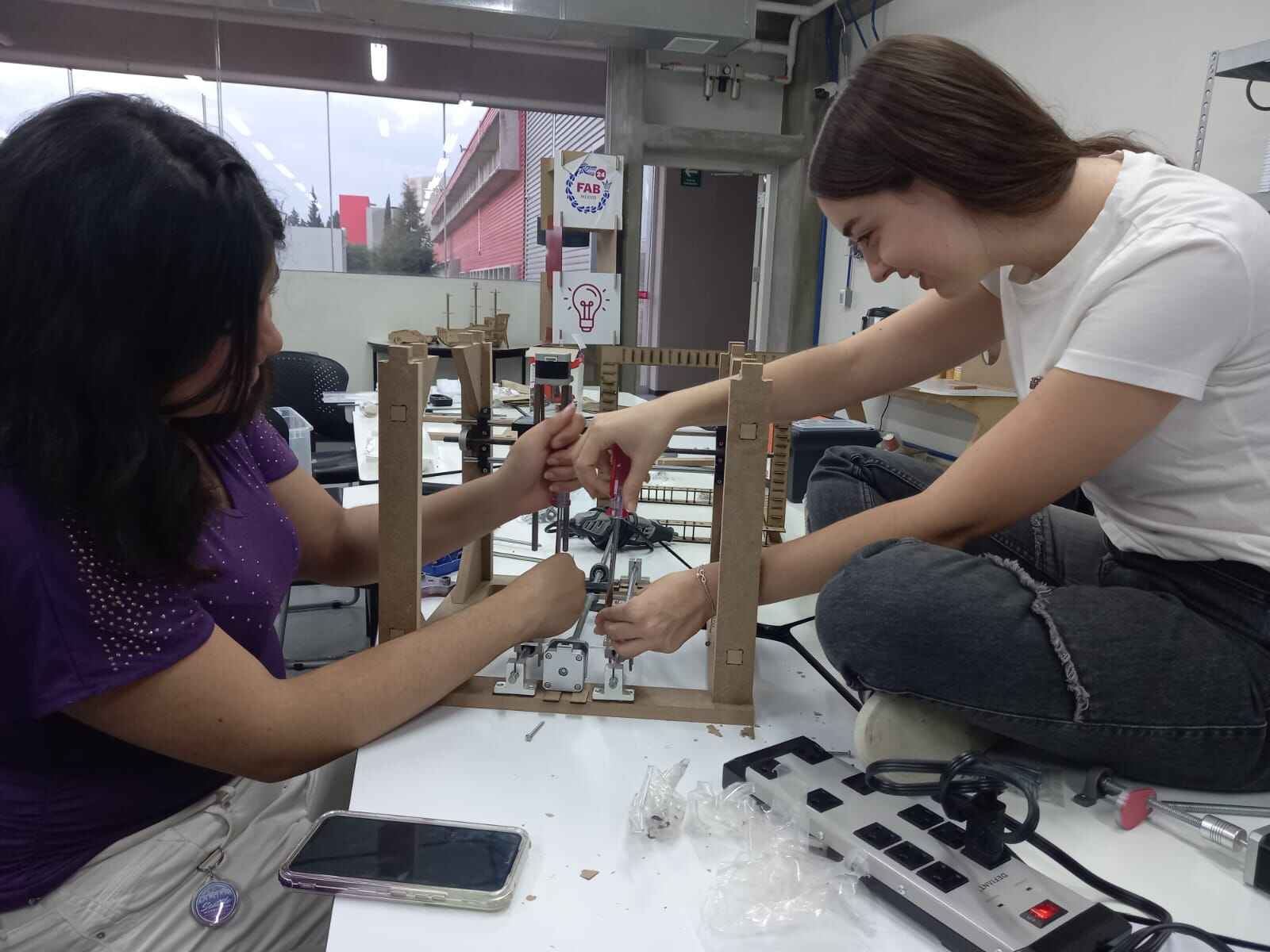
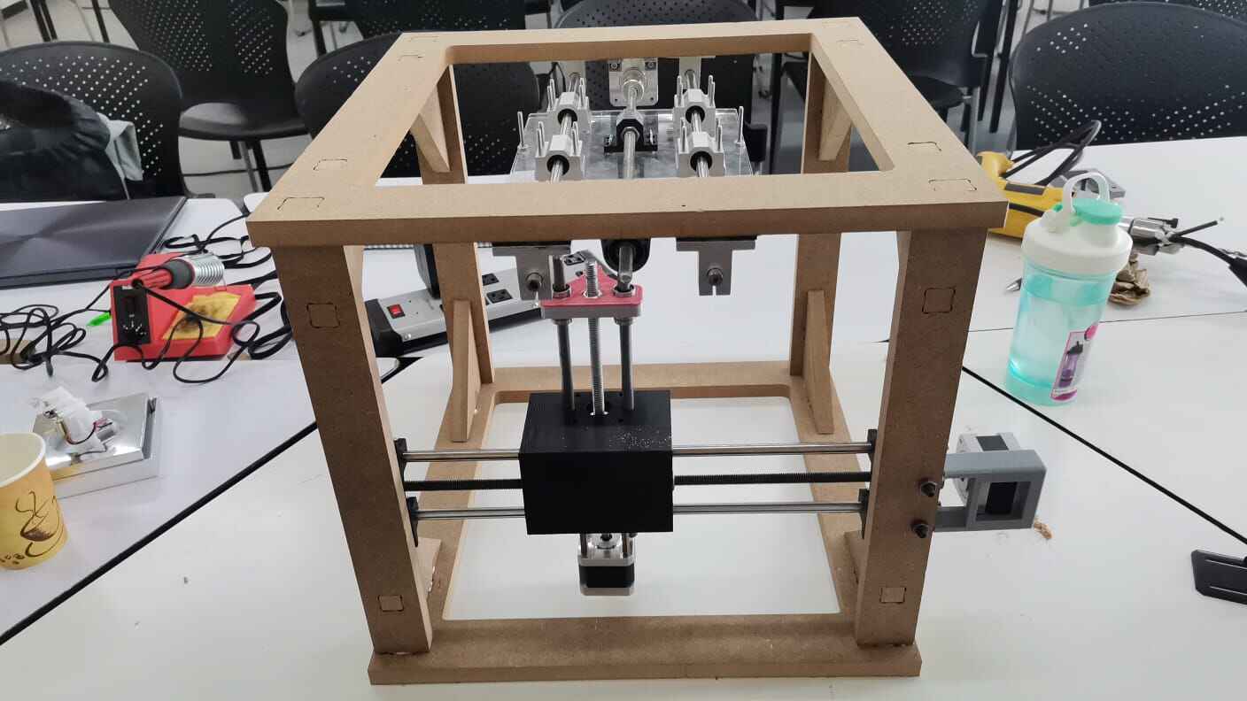
Likewise, during Holy Week vacations, we assembled the first design of the printer designed by Ivy; however, despite the hard efforts of our colleague (Ivy), it lacked stability and was very fragile since we cut it with 3mm MDF, which would make it difficult to use the motors due to excessive vibration. This would result in poor print quality. Therefore,we designed a new model for our food printer in SolidWorks and we used the knowledge of the previous weeks for the following. It's like a wooden cube with triangles in the corners, aimed at enhancing stability and providing robust support. We plan to use 15mm MDF material, cut with a router machine, to give it some weight and make assembly easier. This setup will also accommodate all the electronic components while minimizing any vibration issues.

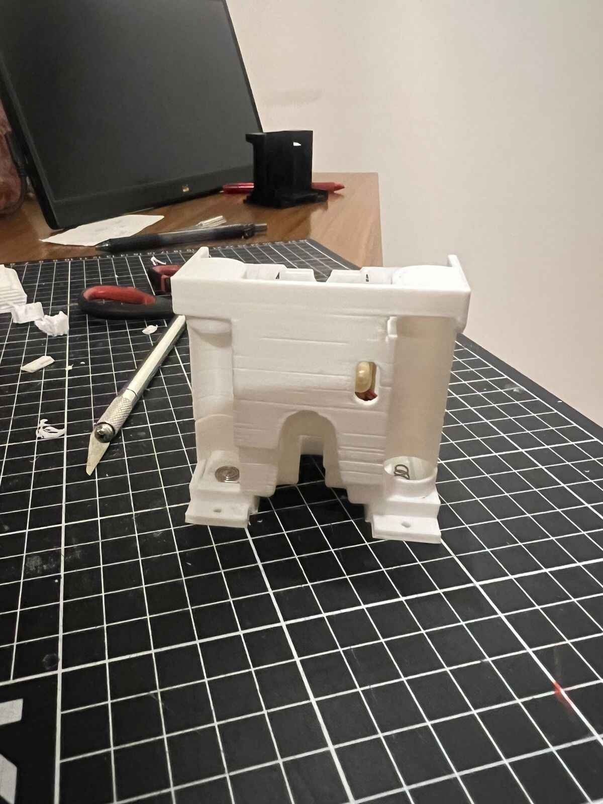
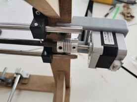
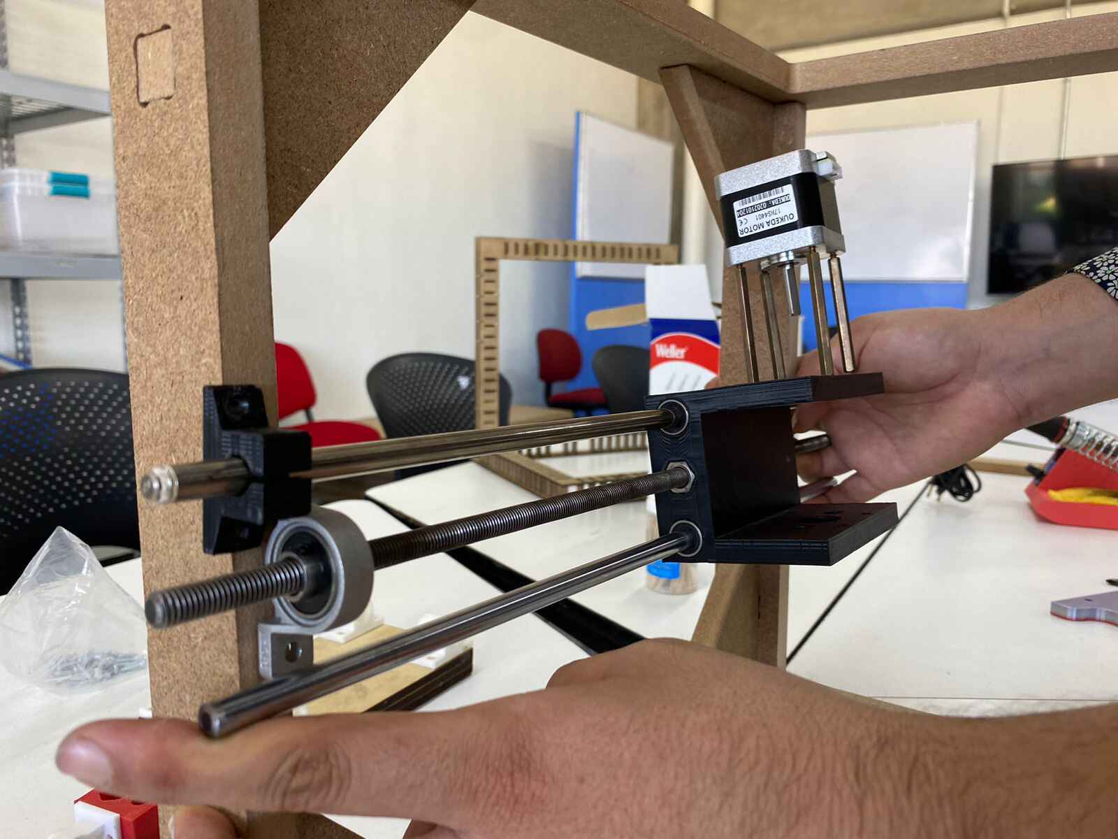
For the motors we had to print some supports for them to adjust perfectly. The support for the Y axis was a rectangle with holes to be screwed to the MDF structure (first picture); while the supports for the X axis were 2 L shaped things (second picture) to screw them to the motor and to the MDF structure.


With the assembly of the impressions in the following way:
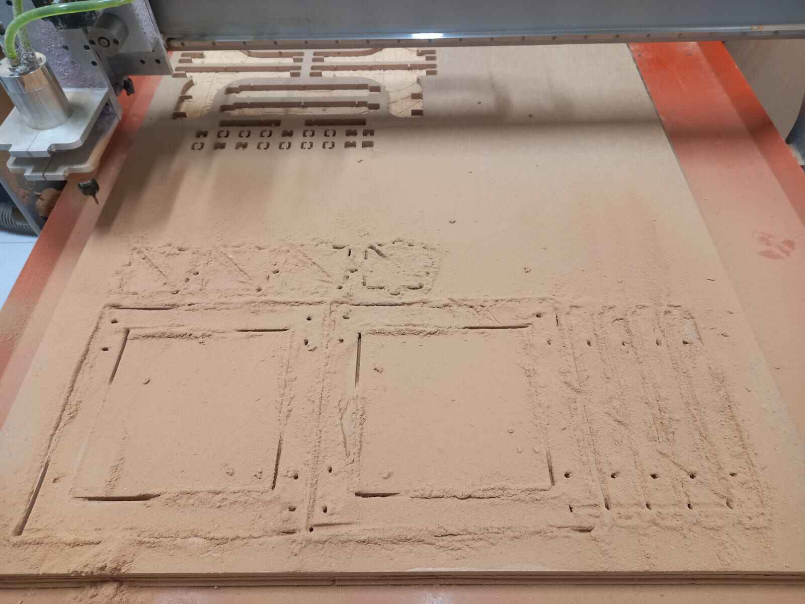
After doing the design in CAD, we cut the structure in the router and did the assembly

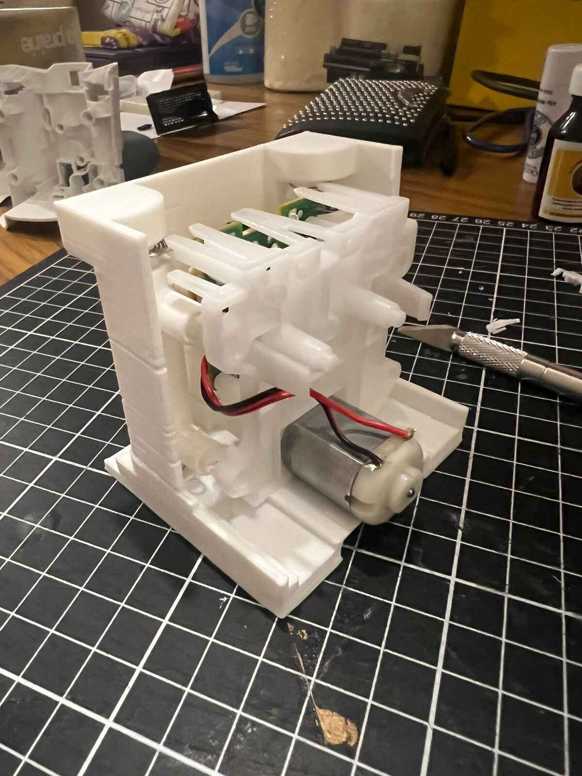
Building
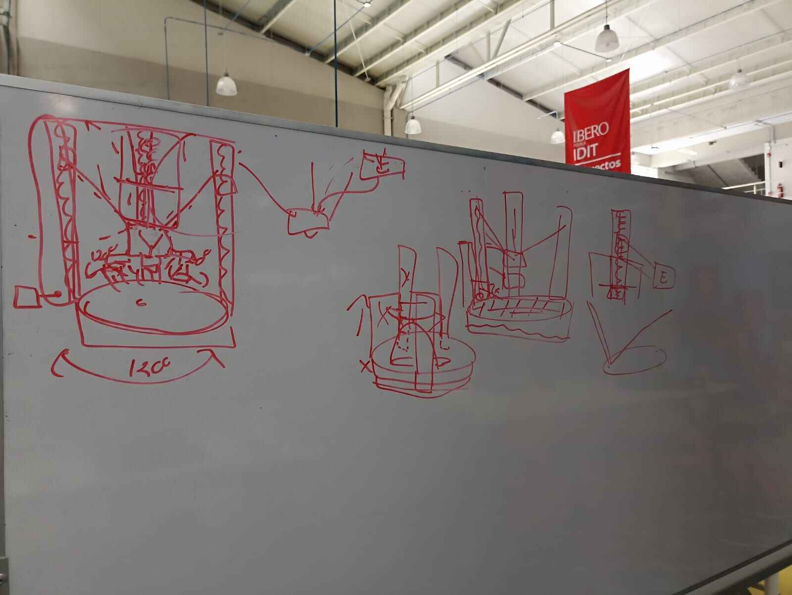
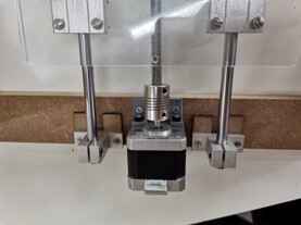
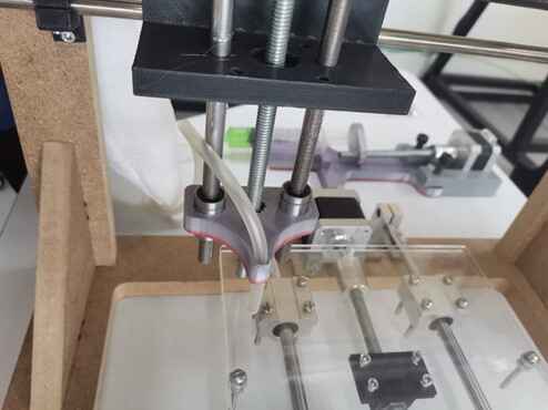
The main problem for the extrusion of the material was that we wanted to place everything on the Z axis, but it would support everything because of the weight. The solution for the extrusion was to use a little hose that connects the nozzle part to the syringe. So we needed a mechanism able to push the material from the syringe to through the hose. The final idea for the extrusion came when we talked to the local instructor and told us that a motor could help us with that. Then came the design of the pieces for the mechanism to connect the motor to an endless screw and to the syringe. The first sketches are the following:
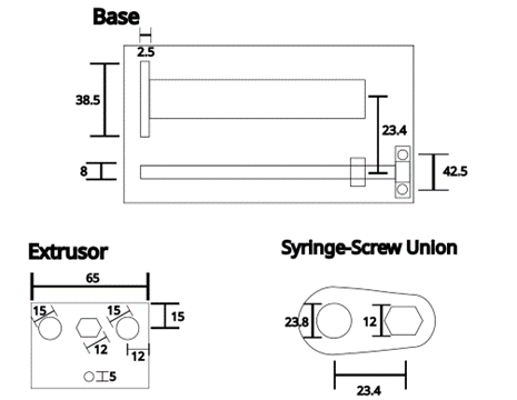
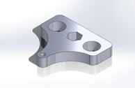
Then came the design in SolidWorks, in which there are some minimum differences from the original sketches in order to improve the impression time.
And the impression:
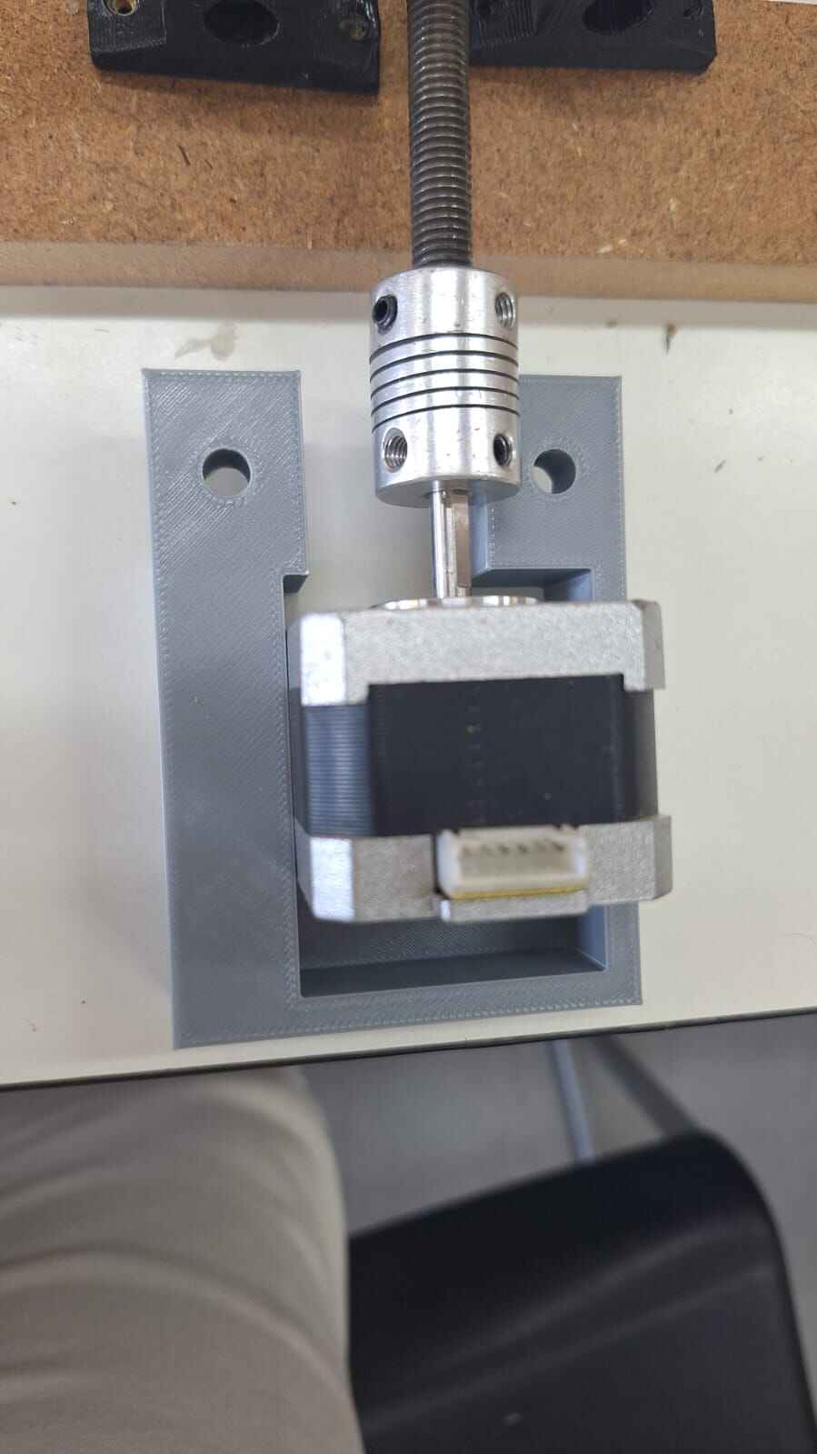
Then we secured the motor for the syringe with a support similar to the one in the Y axis:

And the extruder was assembled in the following way:
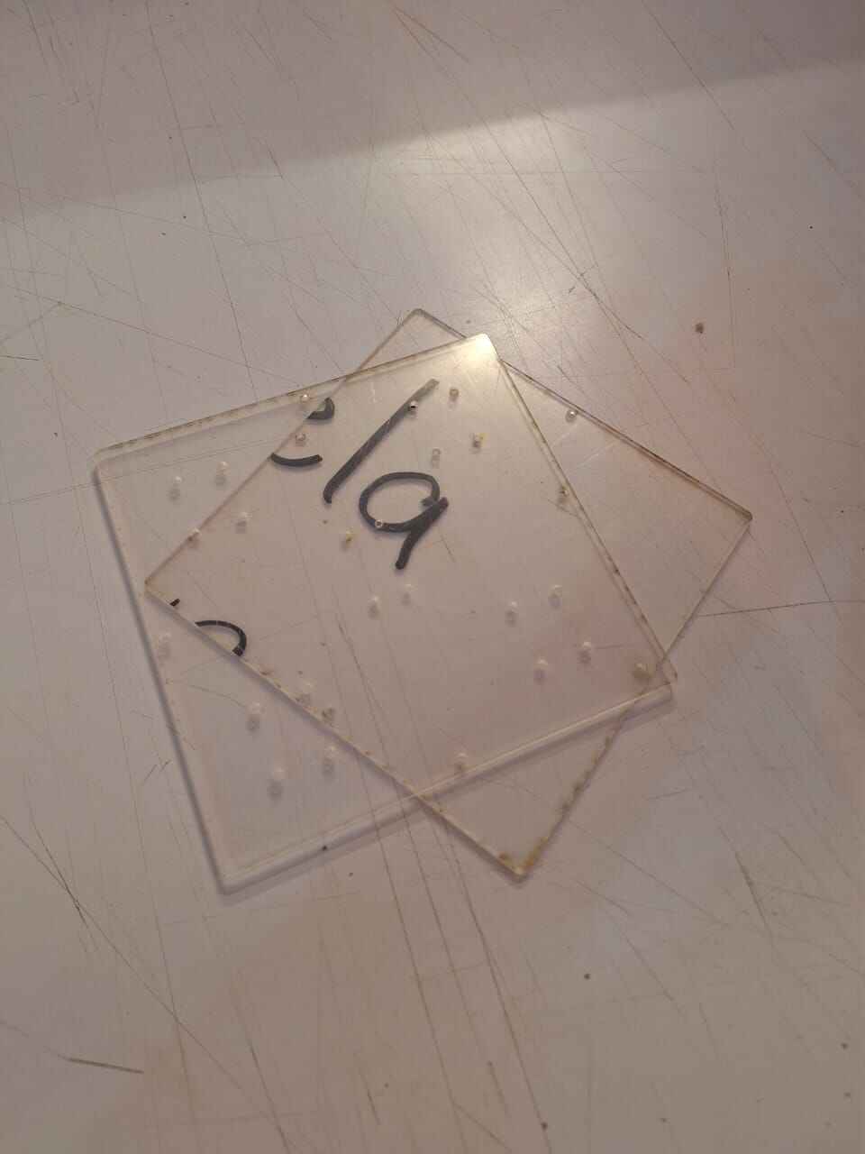
As we made tests on the printing material and the sprayed liquid, we realized it wasn’t really necessary to use a fully holed bed, so we modified the design to reduce the pieces and simplify the process. The pieces were reduced to only two: an upper solid bed and a lower one that had some modifications to attach the bearings. Also, we chose to cut it in acrylic, as it would be more durable even wet.
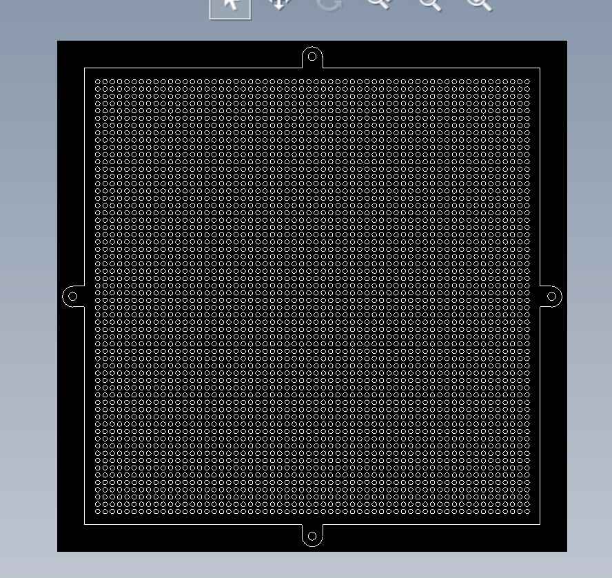
We also came to the conclussion that we could use acrilic for the base plate. Since we needed something that would not absorb the solution. This would also be easier to clean and unstick the printed piece from.
With the structure finished, we began adding the mechanical and electrical components to the printer. Such as the motors, endless screws, sliders, supports, etc.
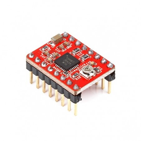
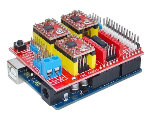
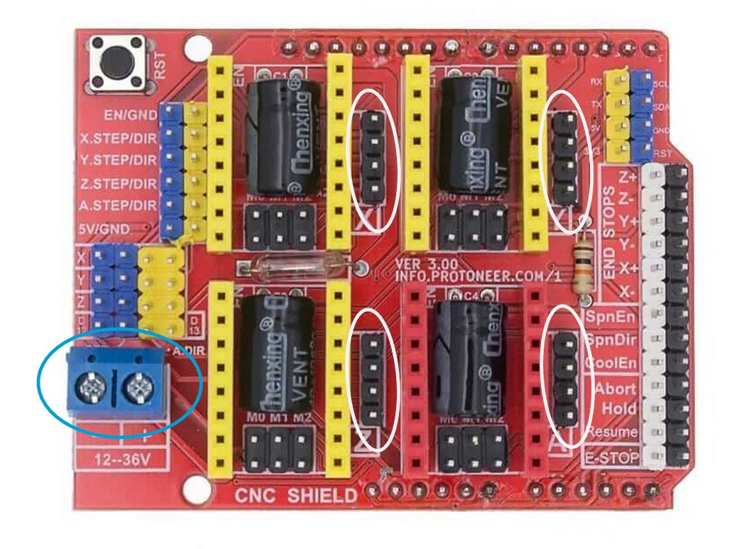
CNC Shield
Then came the CNC test with the motors and the drivers. The working of the machine lays directly in the CNC shield. The machine consists of 3 step motors (Nema 17) with their corresponding motor controllers (A4988) and their radiators, it had 3 cables as well to connect the step motors to their drivers.
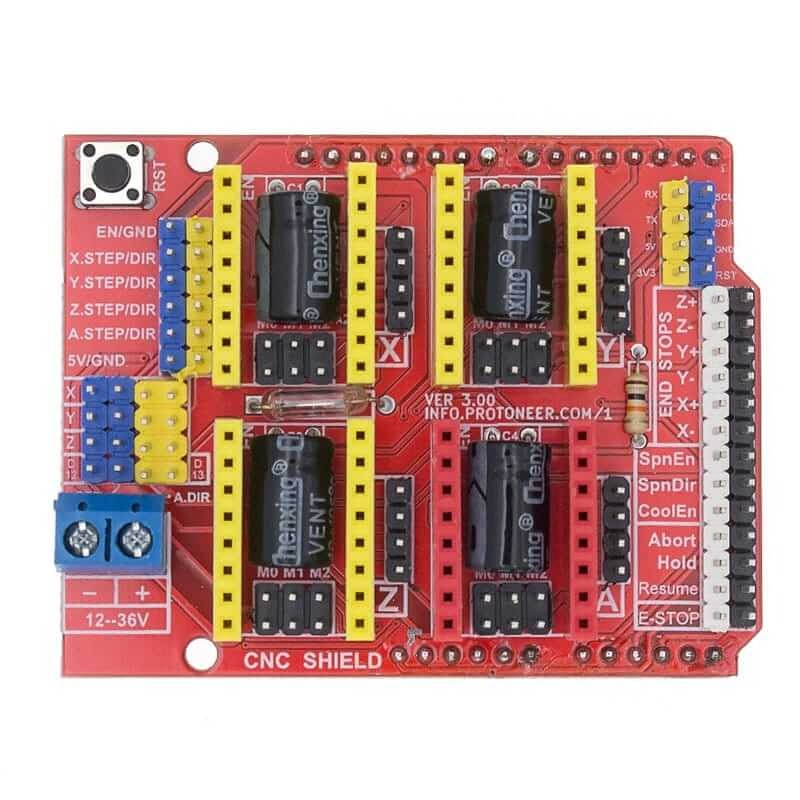
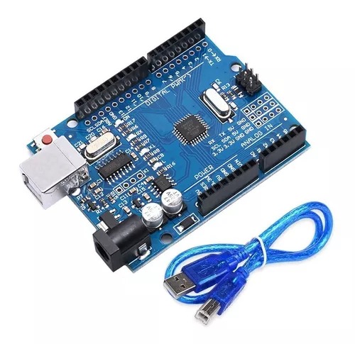
The drivers must go connected to the shield, while the shield has to be connected to the Arduino UNO:
In the blue connector from the shield go the connections for the power supply, which has to be adjusted with a screwdriver. The cables from the motors need to be connected to the pins in the white circles:
From now on, the only thing left is the programming. First, the Arduino is connected to the computer through a USB cables, then the Arduino board interprets the G-code to send it to the shield and process it. The shield then sends the information to the drivers, which allow the control of the position and speed of the motors' motion.
Roughly, the working of the code is easy, as it only needs a command to establish the measuring units, the speed, and the positions the extruder must acquire to create the desired shape. The command to set the units to millimeters is G21, then a quick move to the origin is set by G0 X0 Y0. After that, the G1 command is used with the coordinates for the x and y axis with F to specify the speed, for example: G1 X50 Y50 F500 to move to the coordinates (50,50) at 500 mm/min. Finally, the command M30 determines that the program has ended.
Conclusion
After observing the operation of our printer, we consider improving the following: - Properly adjust all axes to not overload them with weight so that they are completely straight and move with ease. - Enhance the stability of the extruder and nozzle to minimize vibration and force generated by the motor. - Position the y-axis more towards the center of our machine to fully utilize the entire print bed. - Maintain the printing material in better condition as it starts to deteriorate after 4 days.