WEEK 7
COMPUTER CONTROLLED MACHINING
This week was about making a Computer Controlled Machining, or also known as Computer Numerical Control (CNC). This process is carried out with computer controlled cutting tools, this allows to have parts of specific shapes and sizes and sometimes of considerable thickness in a very short time, helping to make work and production time more efficient. I link it a lot with laser cutting because it seems to me that it is very similar to CNC Router in that sense, only the Router is bigger. I also understand that there are many other types of machines that can be programmed with a post-processed CAD type file to be G-code to control the movement of the machine in the X, Y and Z axes. However, this time we are focusing only on the CNC Router.
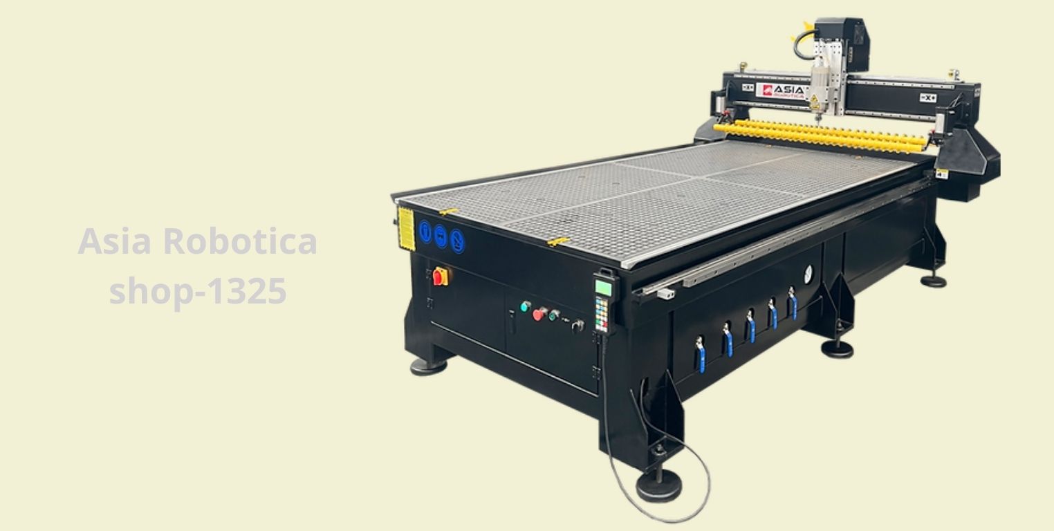
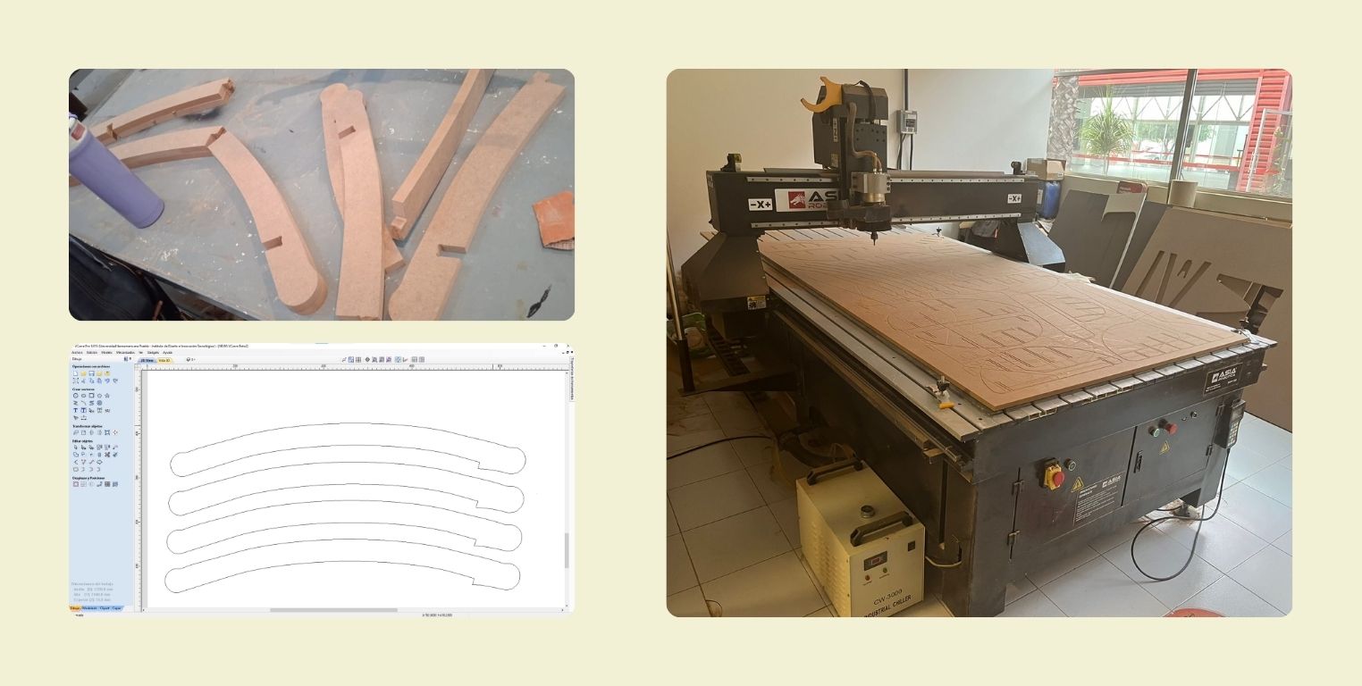
At FabLab Puebla IDIT we have two CNC machines for this week, they are the Asia Robotica shop-1325 Routers and a generic machine made by the university. I invite you to see the specifications of both in the link of group practice. For my assignment this week I used the Asia Robotica, not for anything specific, but that was the one I had to cut, and the truth is that it was very easy for me to understand how it worked despite being the first time I used it.
During the elaboration of the group assignment I had the opportunity to learn some general aspects that could be useful for me when doing the individual assignment. Below is the list of the aspects to keep in mind, but you can also see more of the group assignment in the following link.
Aspects to take into account when configuring the cut:
- The file that sends the coordinates to the machine is a G-Code.
- For the GCode you need to pass the file in DXF (if it is a 2D drawing) or STL (if it is a 3D drawing) through a post processor. In FabLab Puebla we use VCarve for this step.
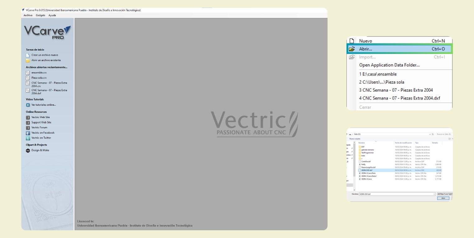
- To open this file in the program click on "Open Vectors" in DXF for 2D or "Open Model" for 3D.
- All vectors that are not going to be worked on should be deleted to avoid the machine passing through the same place twice or cutting a part in an undesired place.
- When arranging the vectors, a distance should be left between each piece, this will depend on the diameter of the cutter, and a little more (minimum 2 times the diameter of the cutter + 10 mm).
- For drilling, short drills are used, but in general the type of cutter depends on the material to be used.
- To set the speed in RPM's it is necessary to make a calculation taking into account the material, however, this amount may vary a little downwards.
- Tabs can be added so that the part is still attached to the material. They are not put where you assemble, they are put where it is easy to sand. But basically they help keep the parts from flying off when you finish cutting because of the vibration of the bed while you are cutting the remaining parts.
- The cutting order in the configuration should be as follows:
- Profile Inside
- Profile Outside
Before cutting on the machine you should verify that:
- You are wearing safety equipment (gown or coveralls, boots with protection, safety glasses and avoid loose hair and objects or garments that can hang down.
- The floor is clean.
- Emergency stop is in place and working.
- General check of the machine for rails and sensors, because sometimes they are not working properly.
- There is a sacrificial layer on which the material to be cut can be placed and occupies at least the area of the material thar is being placed on top of it.
- That the material is securely fastened to the cutting table.
- Store "0" in X and Y always in the lower right corner.
- Once the part is stored, send the tool to a safe place.
WHAT DID I DESIGN THIS WEEK?
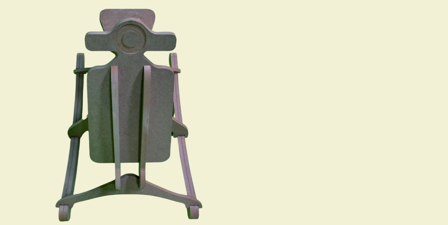
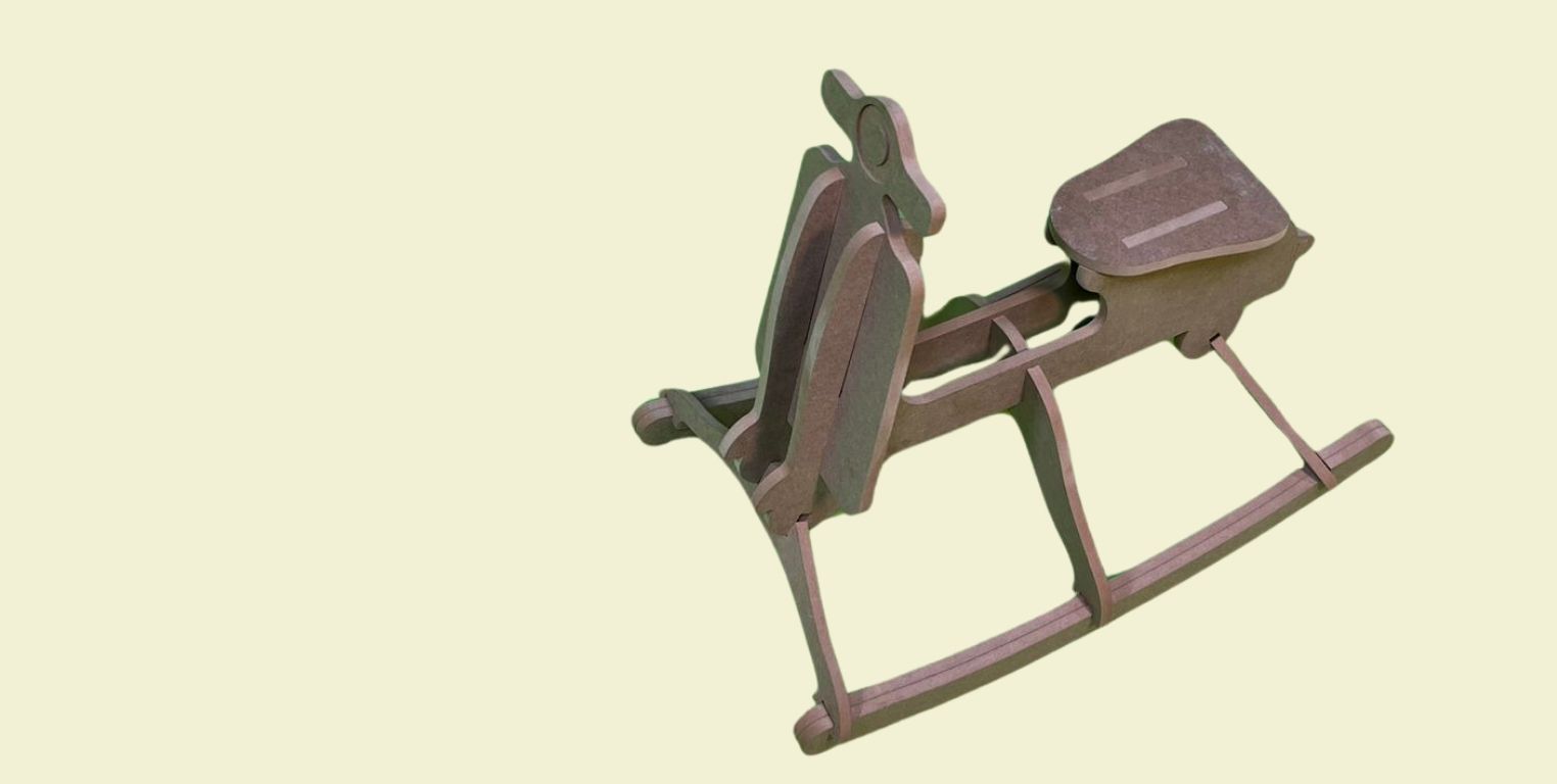
For this week I prototyped a Vespa rocker for my youngest nephew. He will soon be 2 years old, so I thought I could make something for the date that is approaching. I was inspired by the existing rocking horses with this type of mechanism, but I wanted to make it in the shape of a Vespa or a motorcycle because my dad likes to ride motorcycles, so I thought it would be a nice touch for him to see his youngest offspring playing on a motorcycle of his size.
JOIN ME TO DESIGN!
I did the Vespa design in Fusion 360, there were several recommendations to do it in Fusion or SolidWorks, but since I don't have SolidWorks installed, I used Fusion, plus it helped me to continue learning the program, plus I really like it because it is very intuitive.
What I did first was to make the drawing of the 2440 *1220 mm MDF board, to be sure that my design could be cut without problems and I was not going to lack of material. In general I used 4 shapes for the Vespa shaped rocker, which was the front, the side part or body, the seat and finally the base of the rocker.
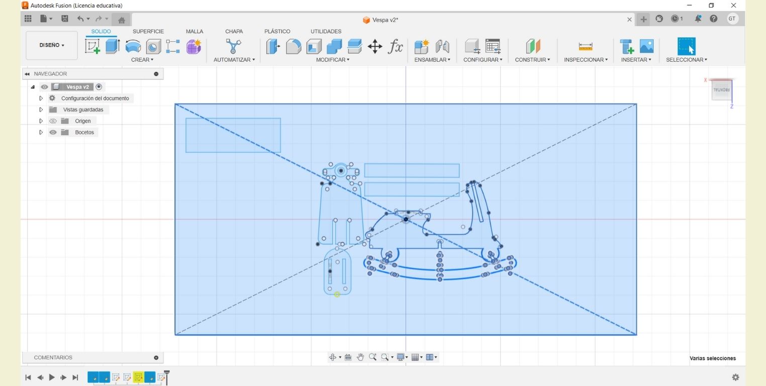
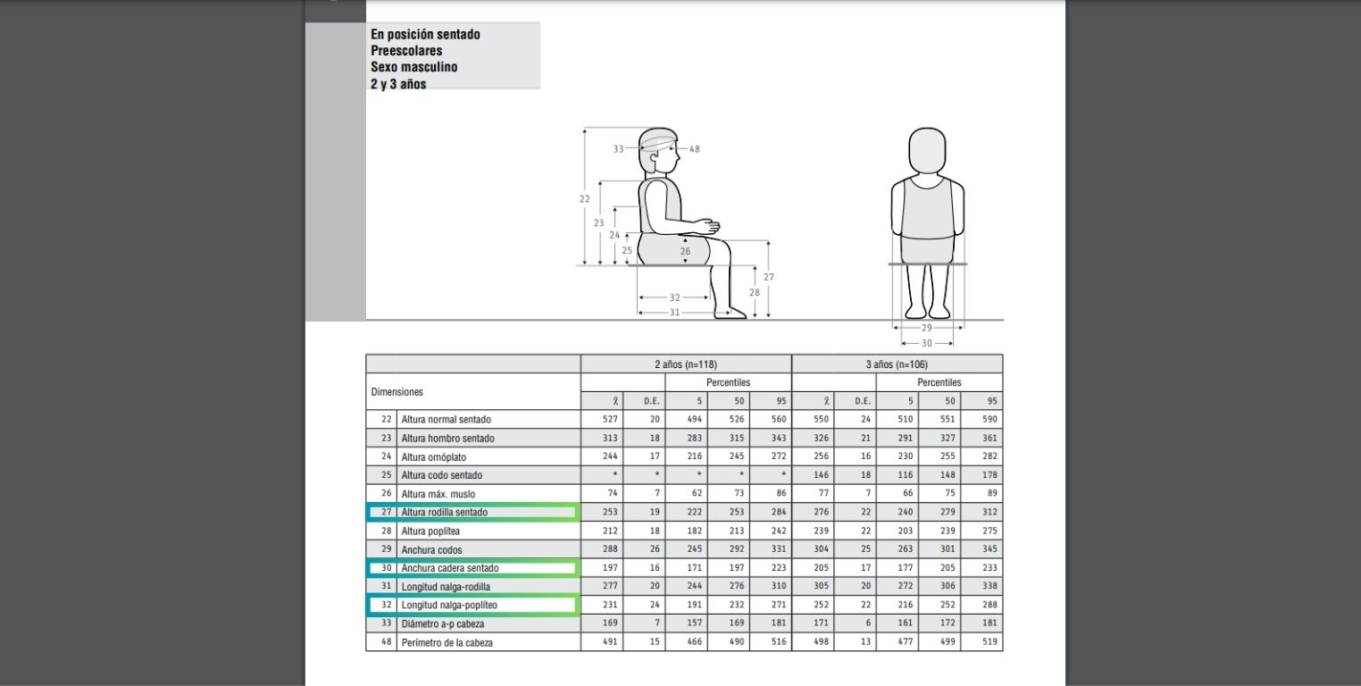
For these priecies I used Fusion sketch tools like "line, curved line, circle from center, chamfer and cut". I didn't really take into account measurements as such for the figures, rather I saw that they were in proportion to each other. And once they were ready, I scaled them according to the anthropometric measurements of a 2-3 Latin American child.
In particular, I took into account the average of the percentiles of the dimensions indicated (these measurements are in mm).
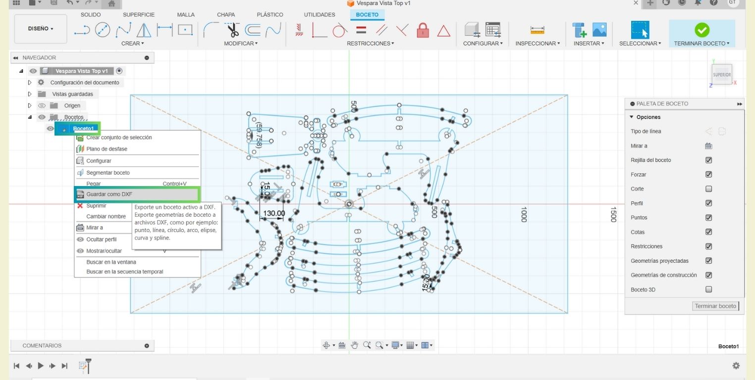
To export the document you can do it as shown in the image below. At first I went to the "file" menu and chose the export option. However, when I opened it in the VCarve post-processor, it showed up as a single line. I assumed it was because I had done it on the "Front" side, so in a new file I copied everything to the top side. But here the TIP is that on the sketch you can click to save to DXF.
Let's set up a cut in VCarve!
First I opened VCarve, and in the "File" menu I clicked on "open" and selected the DXF document that I had previously exported. But if you have the parts in different files you can open one and in the file menu import the others so they are all in the same document.
Then on the left side I put the dimensions of the table in which I was going to cut, in this case it was 2440 mm * 1220 mm * 15 mm Then I clicked on accept and cut the lines that did not serve me and stayed from Fusion.

The next step was to select all my vectors and in the "edit" menu, inside "selection" I clicked on "select all duplicate vectors", this way the duplicate vectors that from the laser cut week left me Fusion would be selected. Then I could delete them.
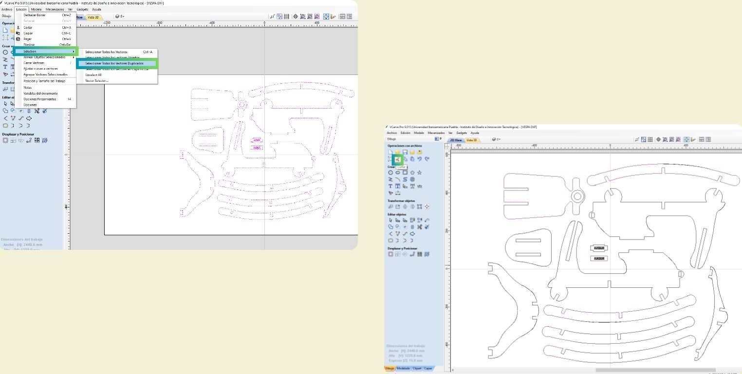
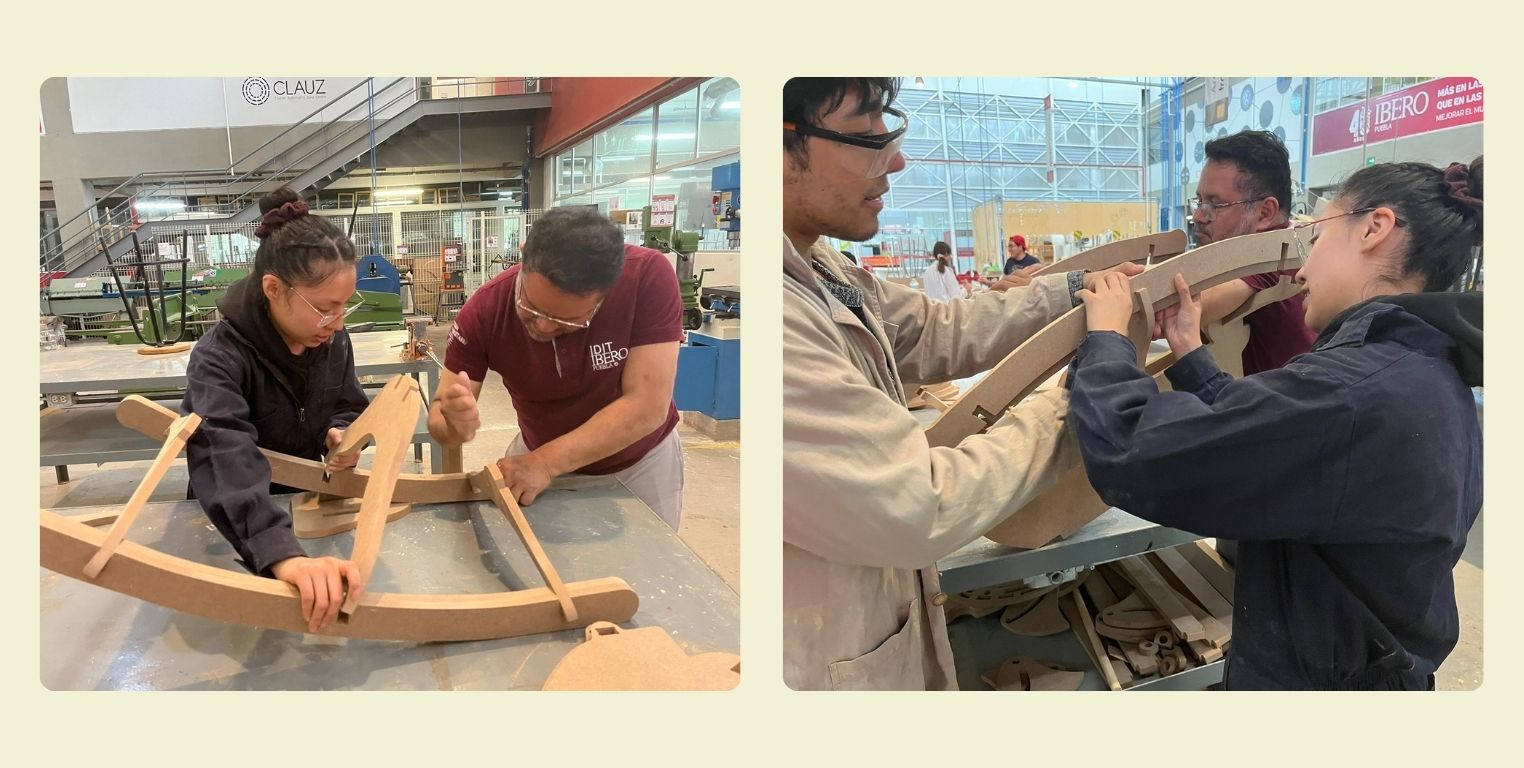
I re-selected all the vectors and clicked on the "join" tool. However after applying it I wanted to verify that my surfaces were well joined, but most of them were not so lucky.
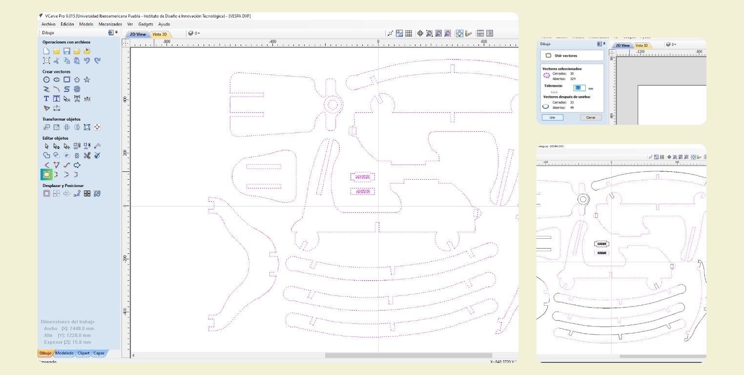
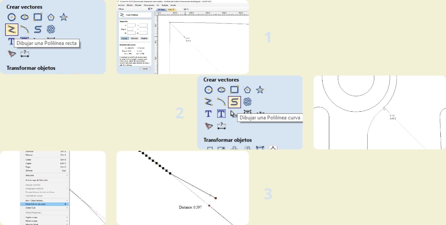
I used the following 3 tools to join my pieces together. In the process I was making sure to start drawing from the nodes of my vectors.
- "Draw straight polyline", I used it to join the straight parts of the figures.
- "Draw curved polyline", I used it to draw on the curved surfaces I redrew-.
- 3 "Node editor mode", right click on the selected vector to move the nodes and join them to others, and delete nodes I didn't need.
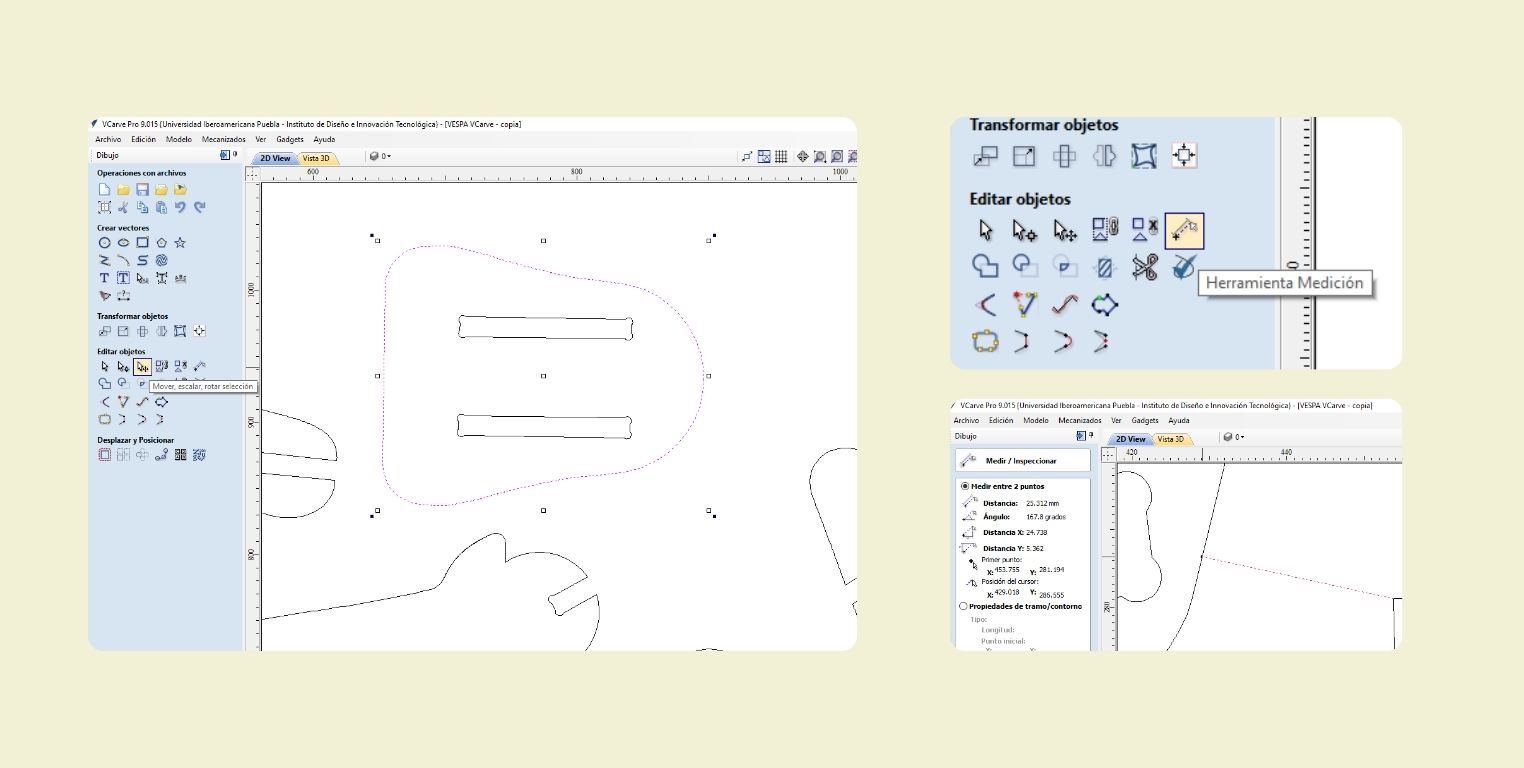
After all the shapes were perfectly joined, I rearranged them to make better use of the material. I did it with the "Move, scale, rotate selection" tool, but it is also activated when double clicking on the selected vector.
When arranging the pieces I verified with "Measure tool" that there was a minimum of 20 mm between the pieces so that there was enough space between each one and I could pass the tool without any problem.
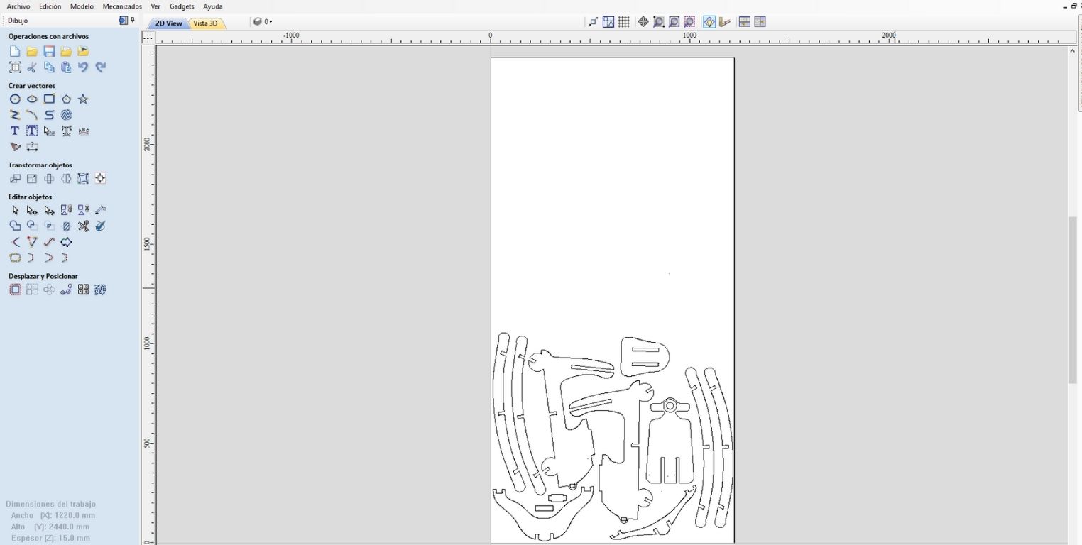
This is a general visualization of how I arranged it in the program. Finally I had half of the material left in case I had to cut it again... And it's a good thing I did, you'll see later why.
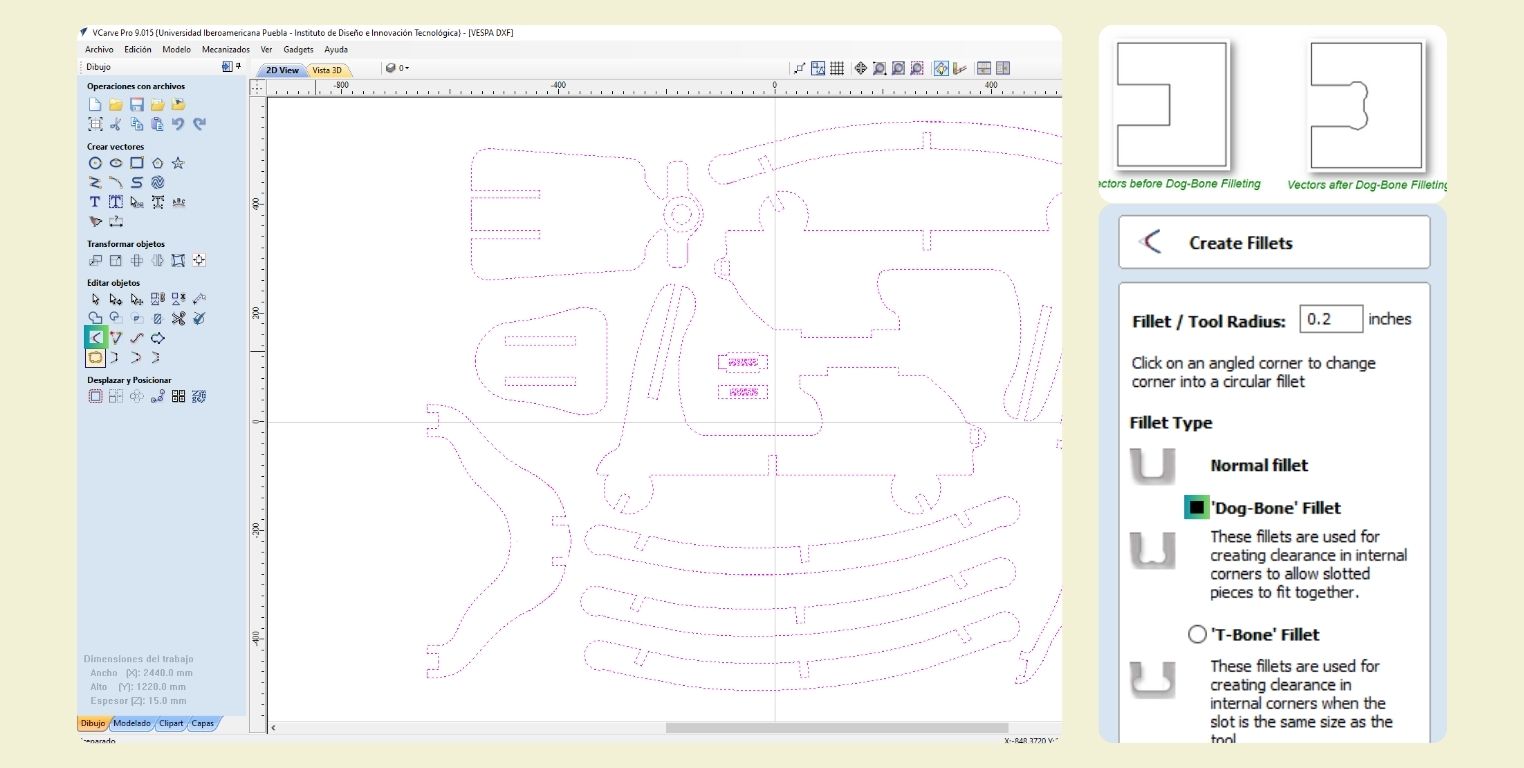
Before proceeding, I used the "create fillets" tool to create "dog-bones" where the assemblies would go so that the pieces could fit easily. There are different types, in this page you can find specifically what each one is for, and I consider that it is a very complete manual that helps you to understand VCarve.
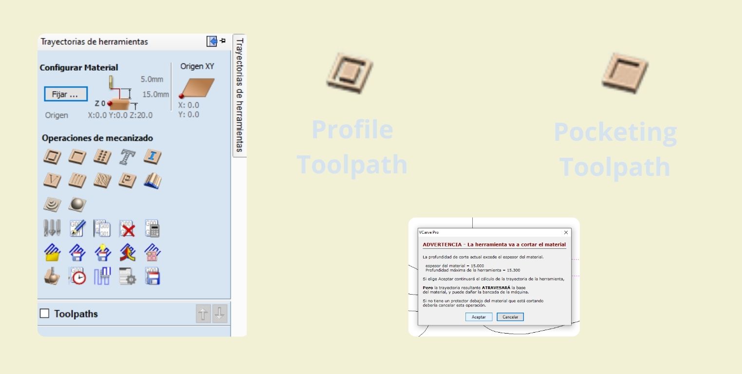
To configure the cuts I used the menu at the top right. Specifically I used Profile and Pocket
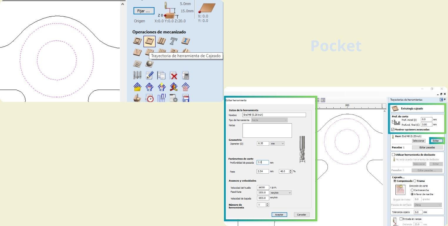
I started by making the pocket that would help me to simulate the Vespa's headlight. To do this I selected the pocket tool and in the "depth of cut" section I left the initial at 0 because it is the surface of the material, while in depth I gave it a value of 3mm, so that a cut would be made on that surface 3mm below the surface of the material. Finally, I verified that the tool was correct. We used a ¼-inch speendle with a diameter of 6.35 mm. In the depth of the pass should go half the diameter of the tool, in this case it was 3.2. Then we set each pass to go down 2.54 mm at 40%. For the speendle speed we used 16000 r.p.m., with a feed rate of 3200 mm/min in the speed at which the tool goes down we left 1000 mm/min and clicked on accept. At the end to save this first configuration click on "calculate".
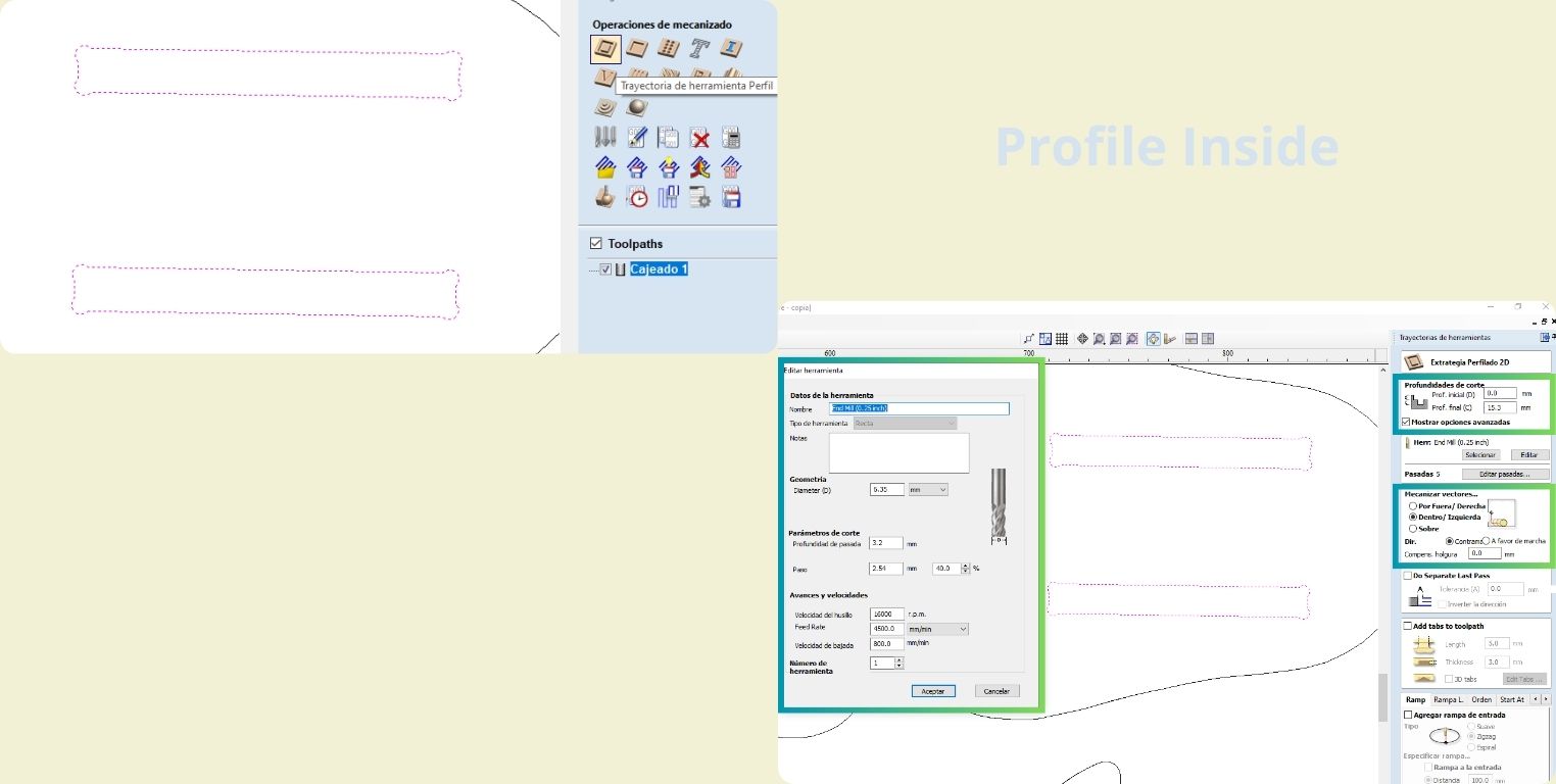
Then I selected the cuts that I would do internally, how do I know it will be about it, well because they are cuts that are inside a figure, and to keep the size of it (it can't be bigger, because it's about the thickness of the material) it has to be done internally. That's why we were told that it practically helps you to consider the Kerf and not necessarily you have to do it, because you can choose not to cut on the line.
The tool that is chosen in this case is the first one, Profile Thool, and the parameters again I left the initial depth at 0, while the final I put it at 15.3 mm, so I make sure that it will indeed be cutting my material which is 15 mm, and I consider that for this you should also take into account the thickness of the sacrificial board, because if this is of a thickness of 2mm, I would have to put at most a 15.1 so that it does not damage the cutting bed. Finally, in the "machining vectors" section I selected the option "inside", in this option you can also find "Allowance offset" that allows you to generate an offset to the figure, which is very useful when you don't want to sand to make the parts fit... Many colleagues had to sand to make their parts fit as they would like, in my case I wanted them to fit under pressure because I was interested that it was sufficiently clamped only with the assembly, so I left this part at 0, with a conventional direction.
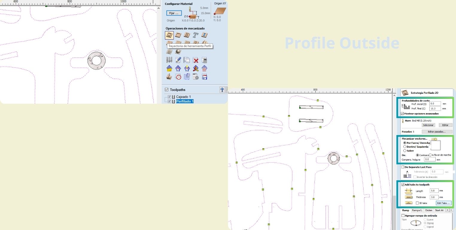
To configure the next cut, I selected all the vectors that generate a figure and are not inside another (those were the past ones), to choose the same 2D profile tool, with the same depth as the past one, only now instead of making the cut on the inside, it would be on the outside. I also took the opportunity to add tabs, what they do is to hold the pieces so they do not move or shoot out until the machine finishes cutting completely; with the "Edit taps" option you can add, delete or drag tabs to accommodate them at your convenience. I could between 3 and 4 per piece distributed generally by the flat surfaces, because it is more difficult to sand on curved surfaces.
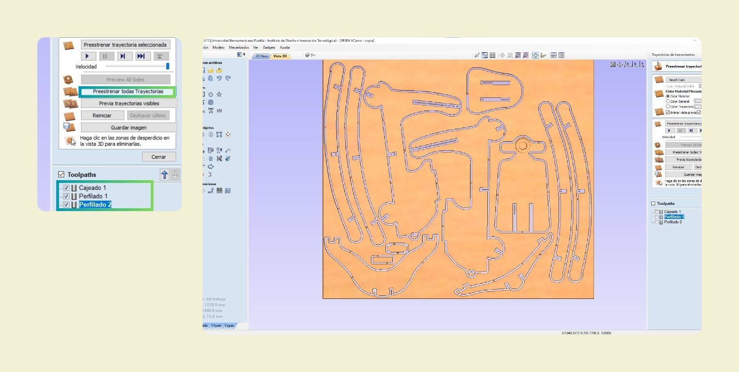
Here is how the 2D and 3D views look like after calculating each of the cuts. Also in the 3D view you can see the path that the tool will follow to cut, always starting with the pocket, profile inside and finally profile outside, and for that you make sure to do the configuration in that order, you arrange them in order in the Toolpaths list.
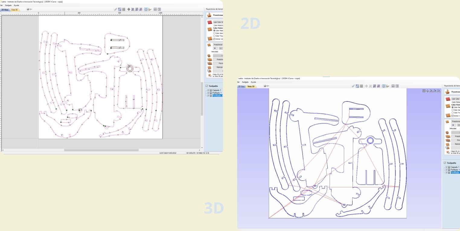
In the 3D view you can select the option "preview all toolpaths" to see a simulation of how each cut would be made and the tabs added.
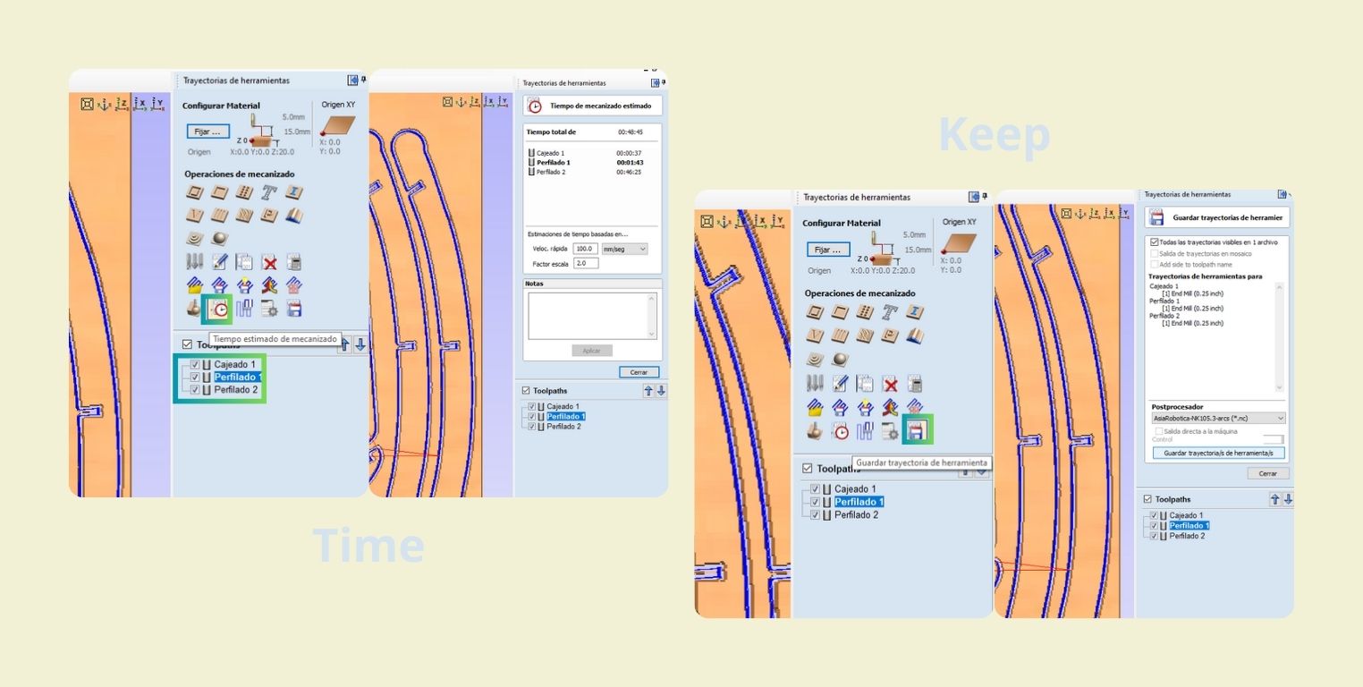
Finally, the program lets you know an estimated time that the cut will take, in my case it said "48 min", make sure you select all the cuts in the "toolpaths" area. It is important to emphasize that the correct way to export the G-Code format in the program is to save the toolpaths, and in this step I chose to do it for Asia Robotics.
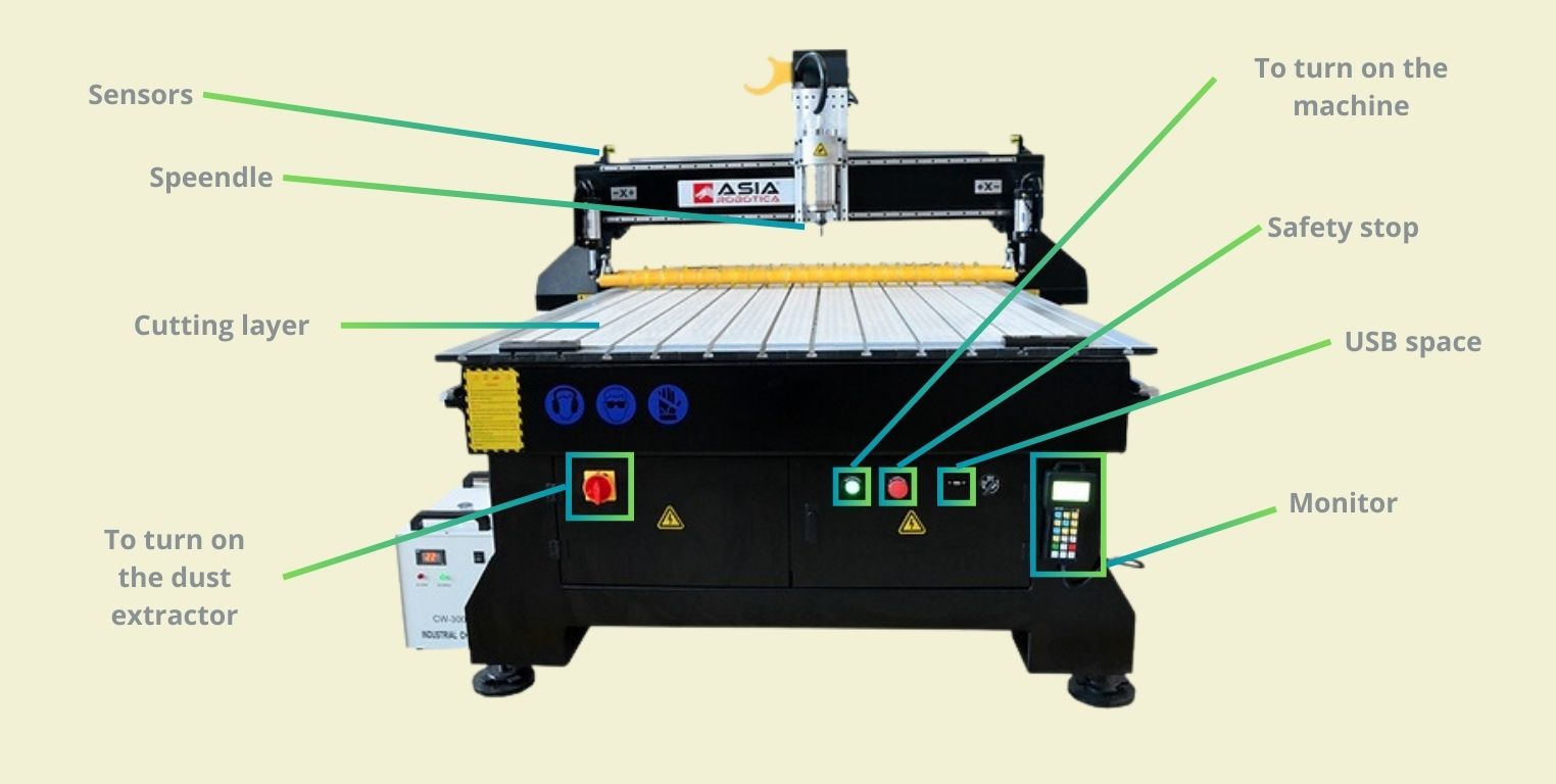
GETTING TO KNOW THE Asia Robotica shop-1325
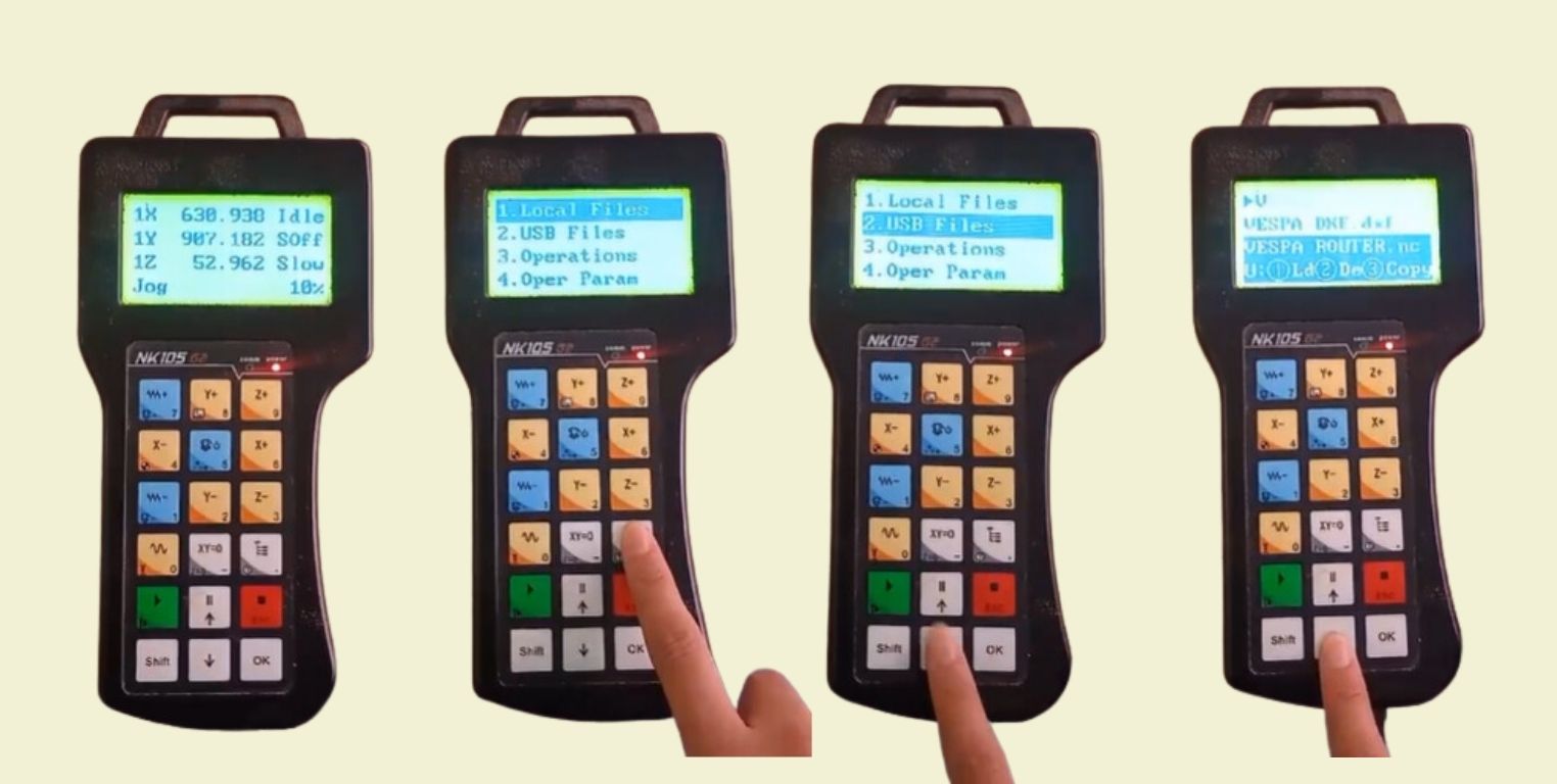
The first step was to position my material on the sacrificial bed, and then secure it. It is important to take into account the distance of the first piece from the ends, so as not to damage the cutter and avoid accidents. I also inserted the USB where my G-Code file was located.
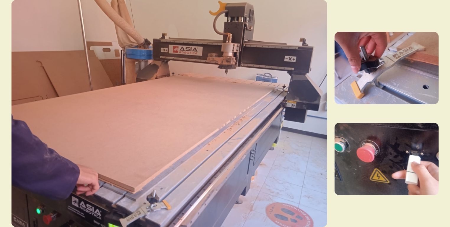
Then with the help of the monitor I positioned and saved the position in 0 of the X and Y axes, and then the Z axis. Once ready I selected my file and clicked play.
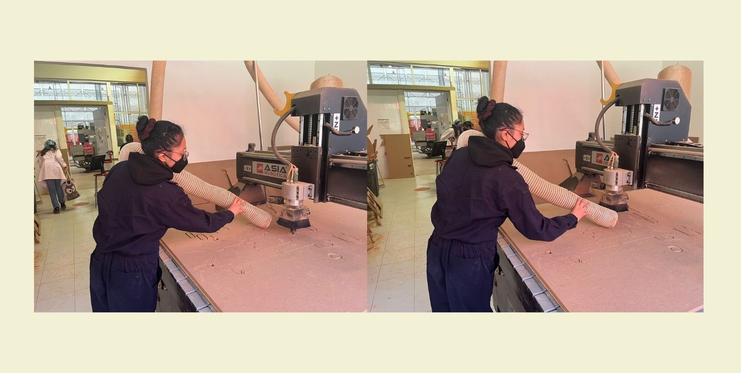
It is important to vacuum the dust during cutting so as not to breathe it in.
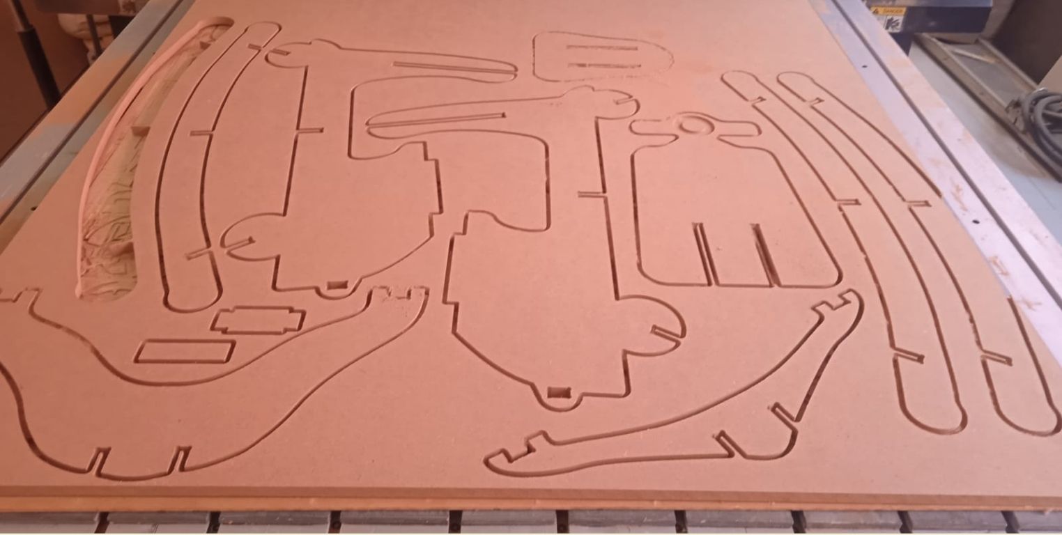
This is a picture once the machine was finished cutting.... As you can see one piece is missing, because it broke.
After I realized that I had missed cutting another piece, so I cut again with a friend, here a test photo.
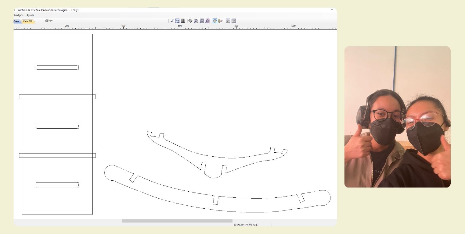
Later I broke again my pieces, and I needed to cut again. It was really sad, and I did a change in my design.
How many people do we need to join a Vespa
Final Resul!
Conclusion
Is you design something that is goint to join en real life, you need to be sure that it will join. My fail was don't prove in Fusion before to cut that all was okay, and I bealive that maybe do it before could save me time. Also is important to verify that all the lines are join, I wasted time doing it before in VCarve, and I sure that it could do it easier. After all, was a good wee, I really can say that I know how to use the Asia Robotica after cut tree time this week, and I also loved to back doing something eith my hands.
Files
- Vespa ___Fusion 360
- Vespa ___DXF
- Vespa ___VCarve
- Vespa ___G-Code