15. Interface & Application Programming
What’s an interface?
An interface is a tool or idea used by technology engineers to facilitate interaction between hardware and software components. They provide communication between all system components via an input-output system and specified protocols, while also allowing for separate functioning.
Furthermore, interfaces allow users to communicate with a variety of devices, including hardware like keyboards, mice, and touch displays, as well as software programs like operating systems and internet protocols.

What’s Figma
Figma is a platform that allows you to create, prototype, develop, and get feedback in one place. You may collaborate in real time, develop realistic prototypes, apply design methods, and explore FigJam, an online whiteboard.
The most important is that Figma enables real-time collaboration while developing and prototyping user interfaces and online applications. Designers may construct intricate, resizable wireframes with interactive features like scrolling and hovering. This produces functional prototypes that can be swiftly tested and refined. Figma also allows users to export code from prototypes for developers after designs are complete.

What’s Tkinter designer?
Tkinter Designer was developed to help Python developers construct GUIs quickly. It makes it easy to create stunning Tkinter GUIs in Python by leveraging the well-known design program Figma. Tkinter Designer utilizes the Figma API to evaluate a design file and generate the necessary code and files for the GUI.
Group Assignment
Visit our group task by clicking on the button below.
What did I do this week?
In order to create an interface for my final project, I set out to develop a system that would enable me to control the color of my Neopixels. To that end, I began with a relatively straightforward programming exercise, in which I simply used a button on my interface to turn on an LED.
Let's start with Figma
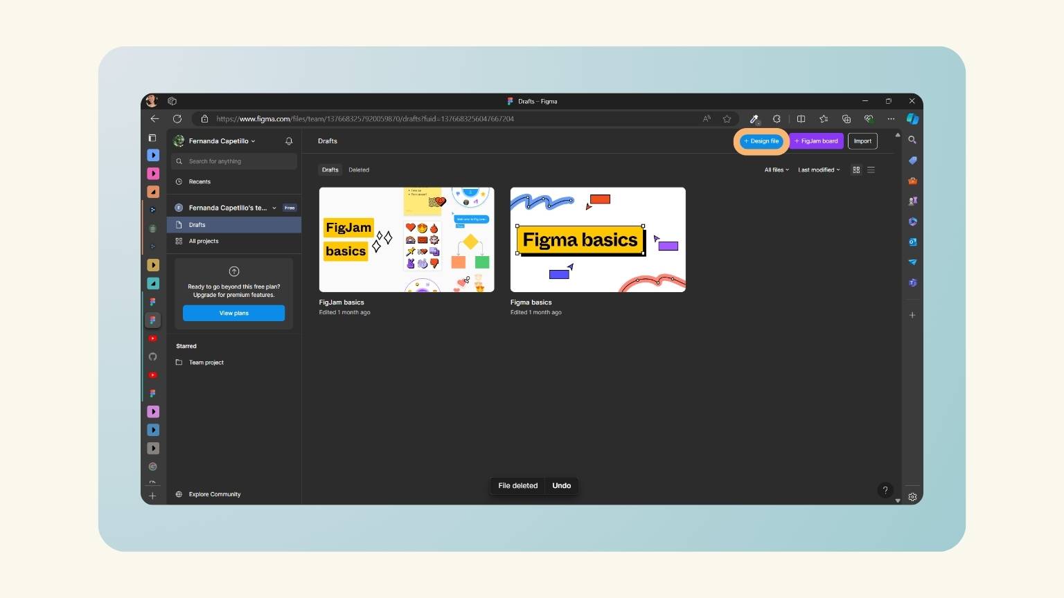
- I created a account of Figma and signed up.
- I clickeon ‘+Design file’.
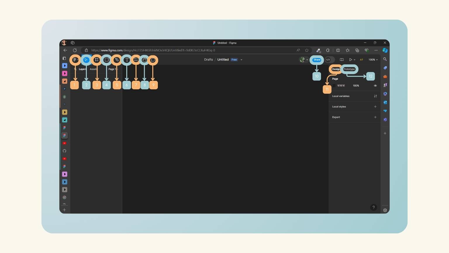
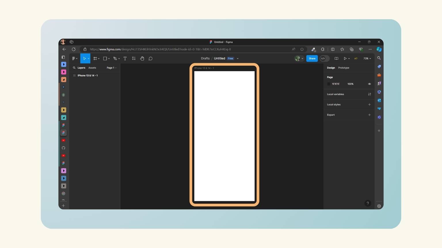
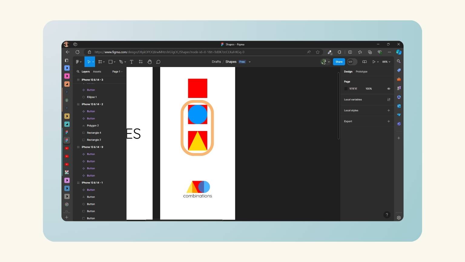
- The subsequent window displayed a variety of menus and tools that could be employed in the creation of the design.
- 1 Main menu
- 2 Move tools
- 3 Region tools
- 4 Sahpe tools
- 5 Creation tools
- 6 Text
- 7 Resources
- 8 Hand tool
- 9 Add coment
- 10 Share
- 11 Design menu
- 12 Prototype menu
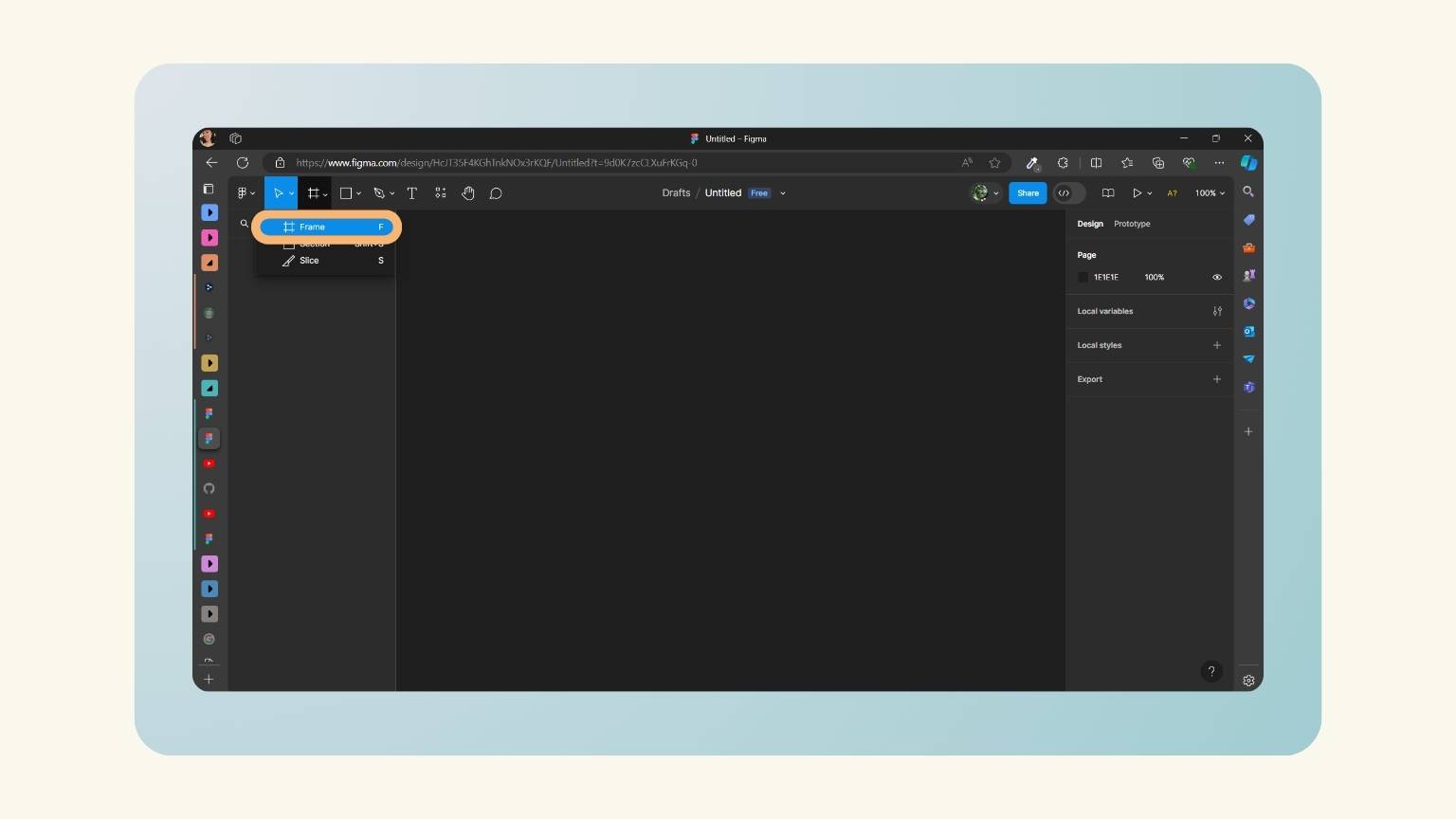
- I opened the ‘Frame’ menu to create the frame of the design.
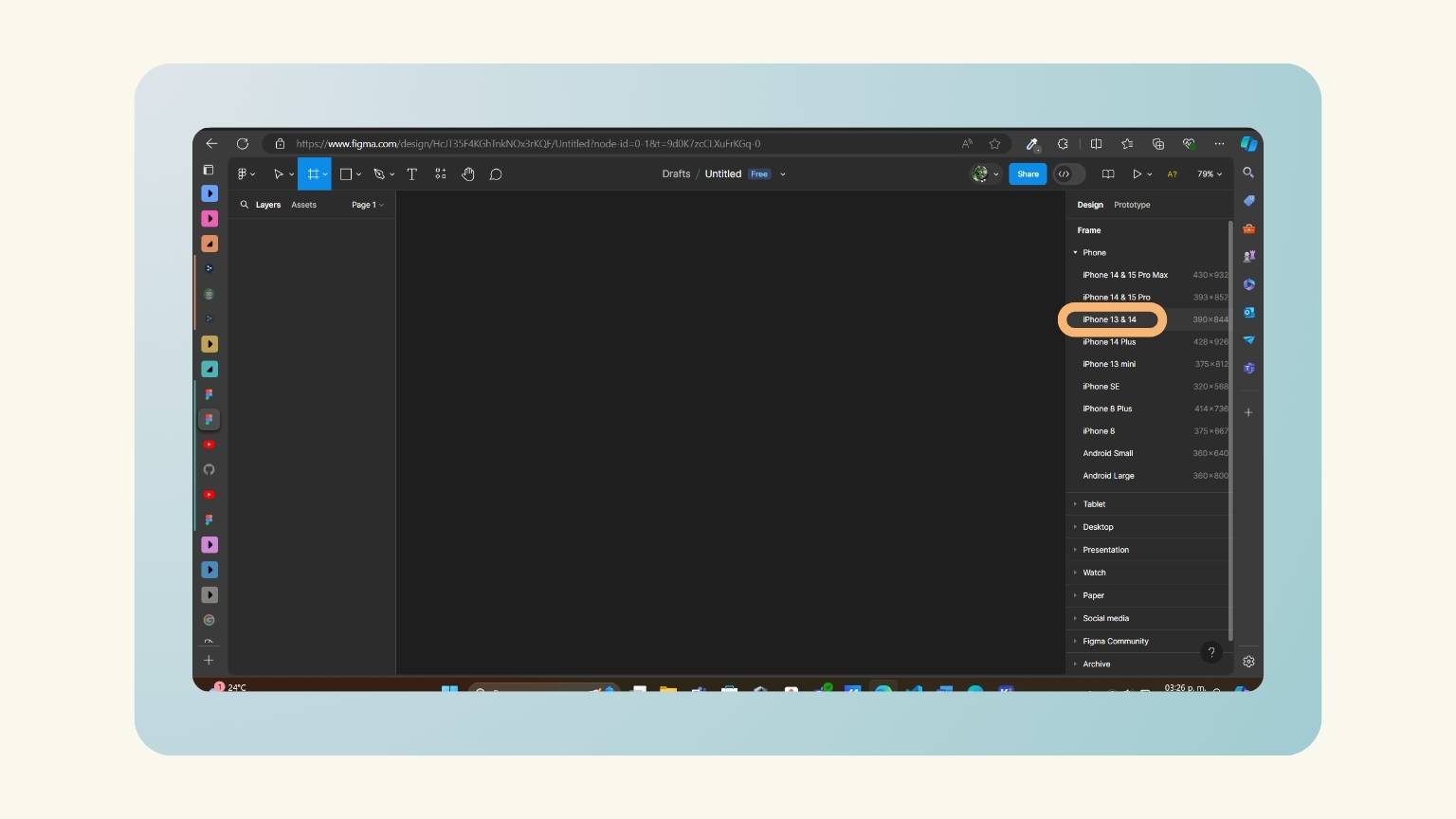
- In the esign side menu, I selected the size I wanted for my design.
- The frame was created.
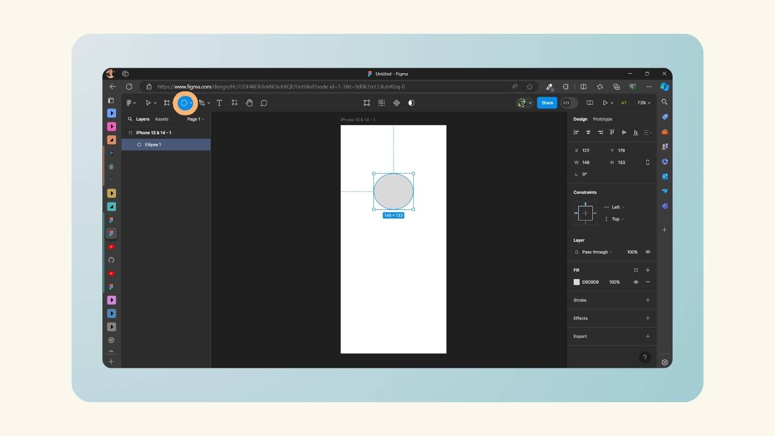
- I created an eclipse with the ellipse tool found in the ‘Shape tool’ menu.
- So, with this tool I created these frames.
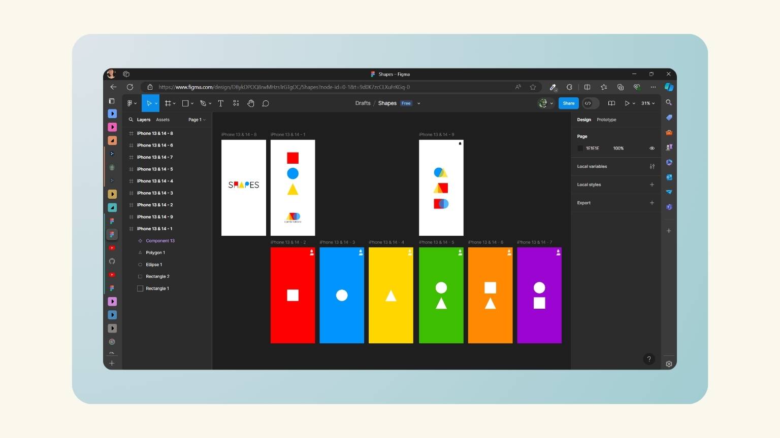
- After, I decided to design another’s frame about the combination of colors.
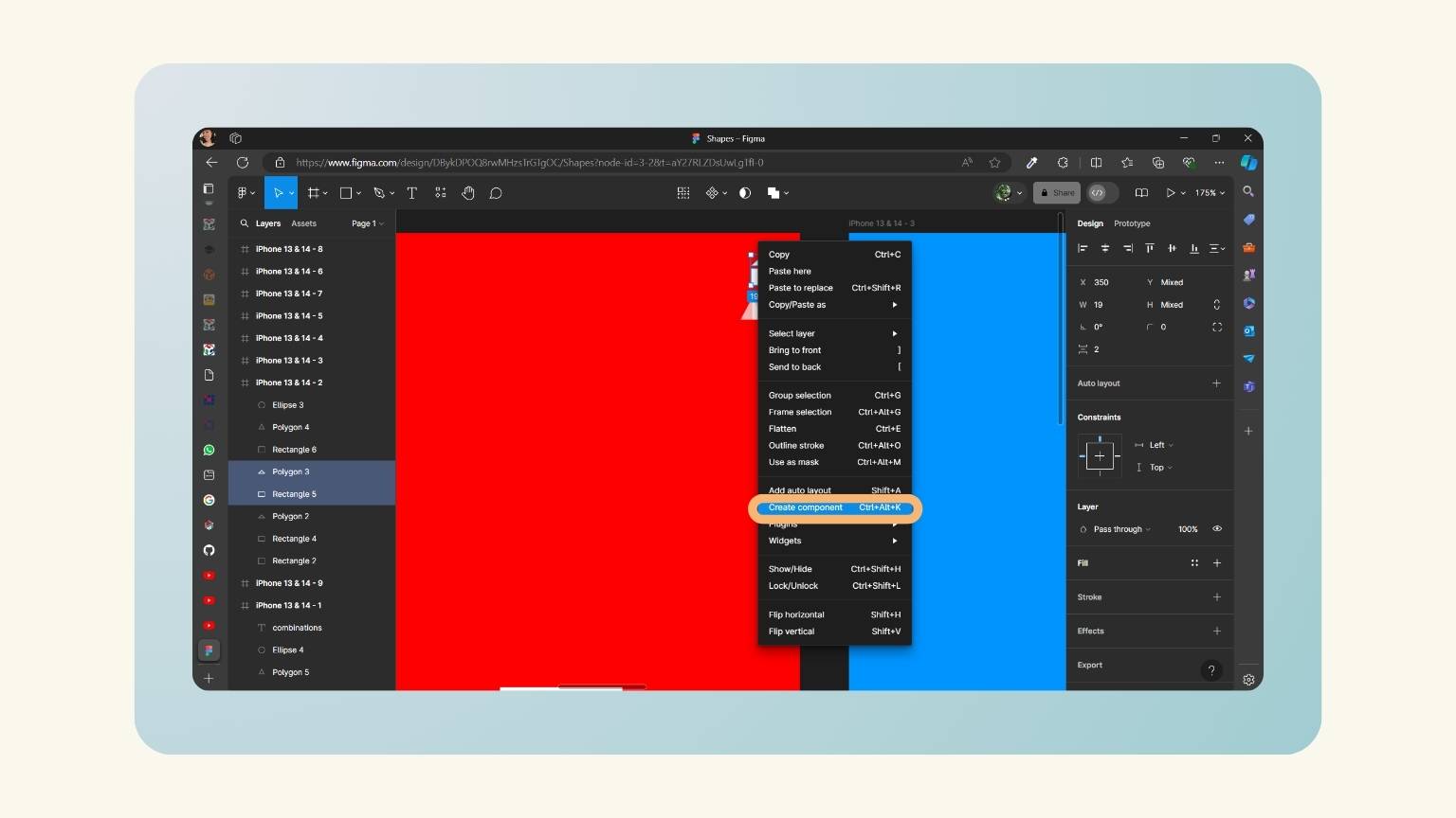
- In order to establish certain connections between the frames, I selected those elements that I would redirect and converted them into a component.
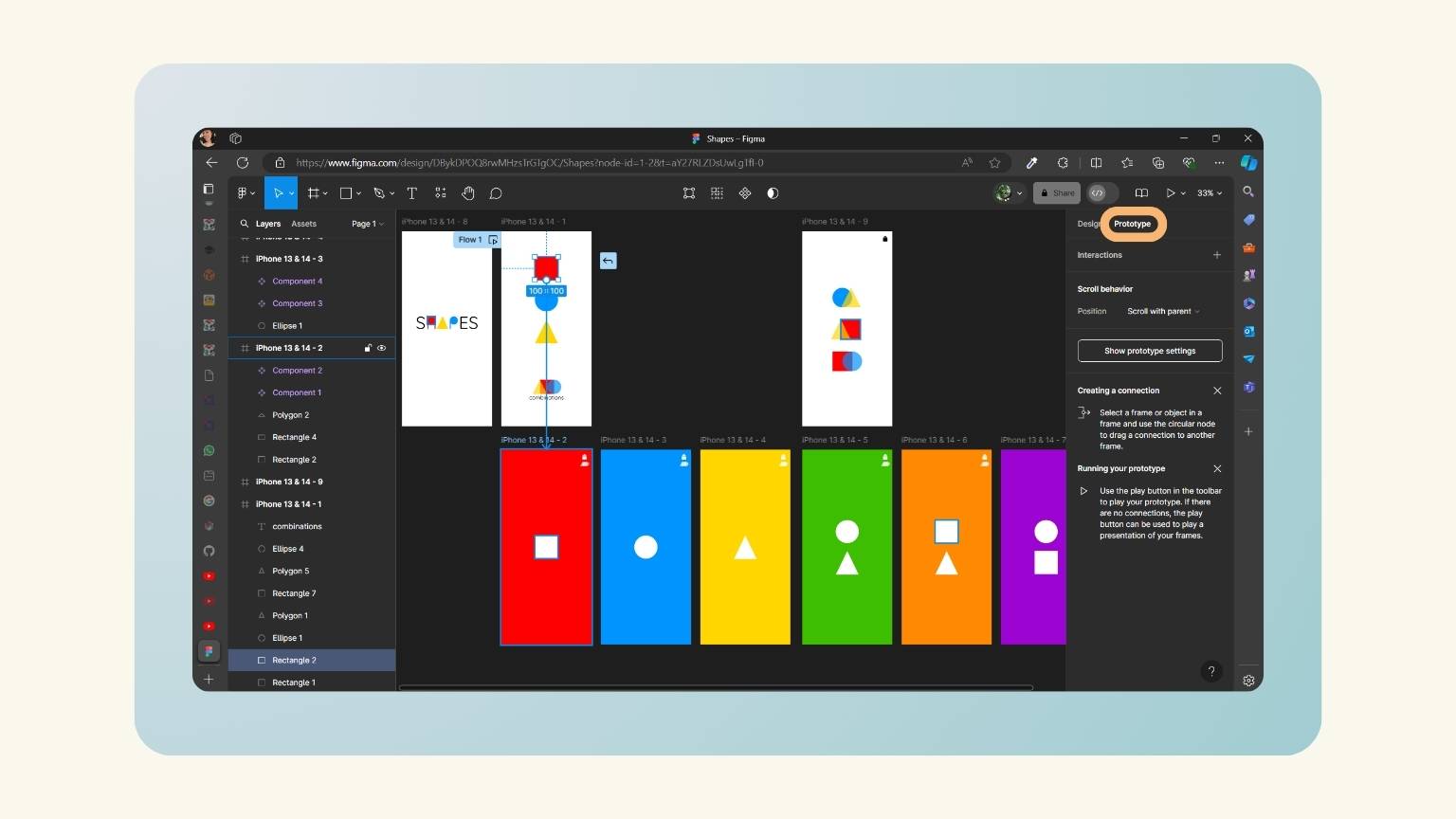
- Then, I began to establish a correlation between the frames, having previously selected the prototype option in the side menu. I then proceeded to navigate to the subsequent frame, which was represented by an object, and created a line to illustrate this transition.
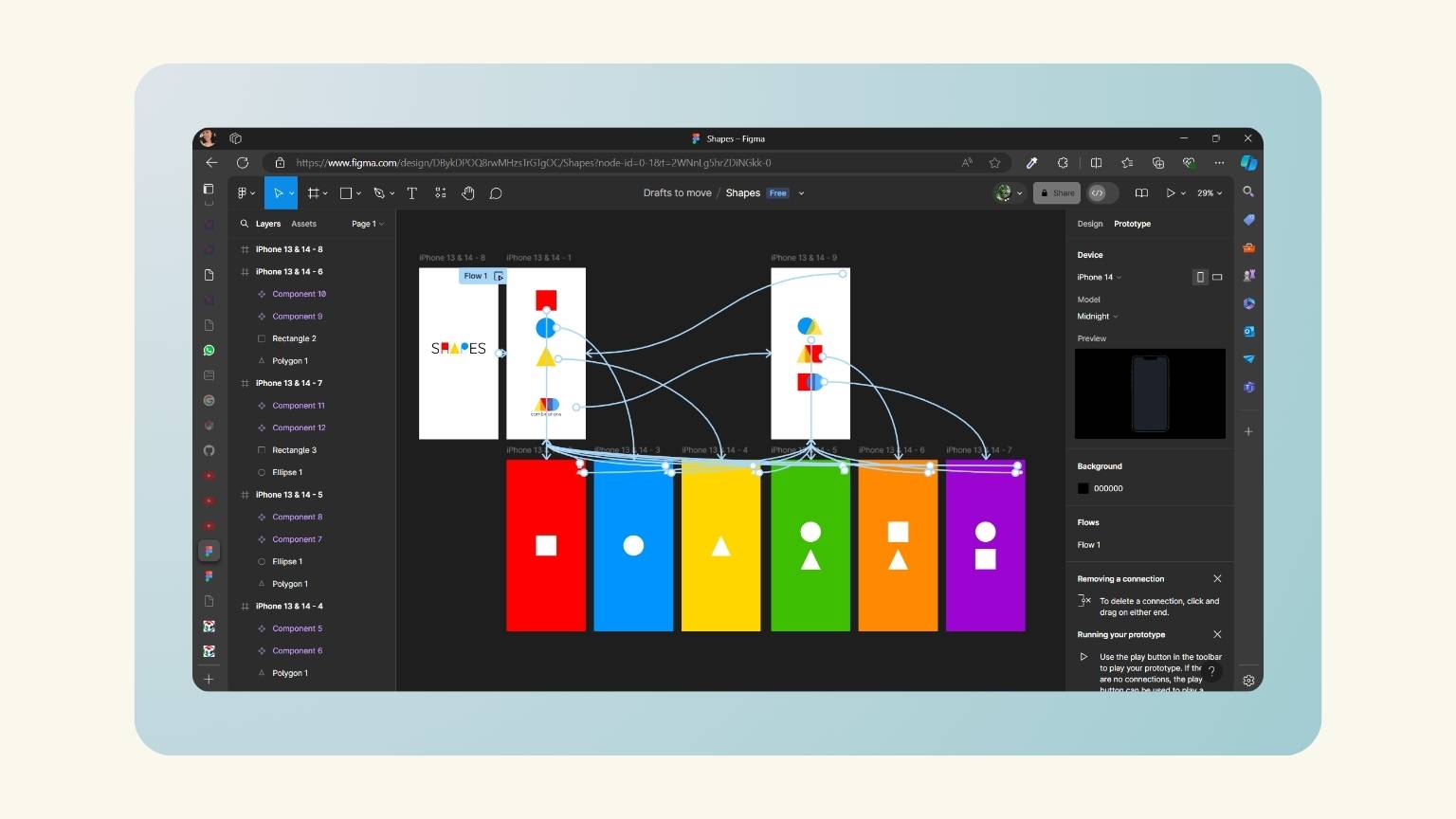
- These were all the connections that I created.
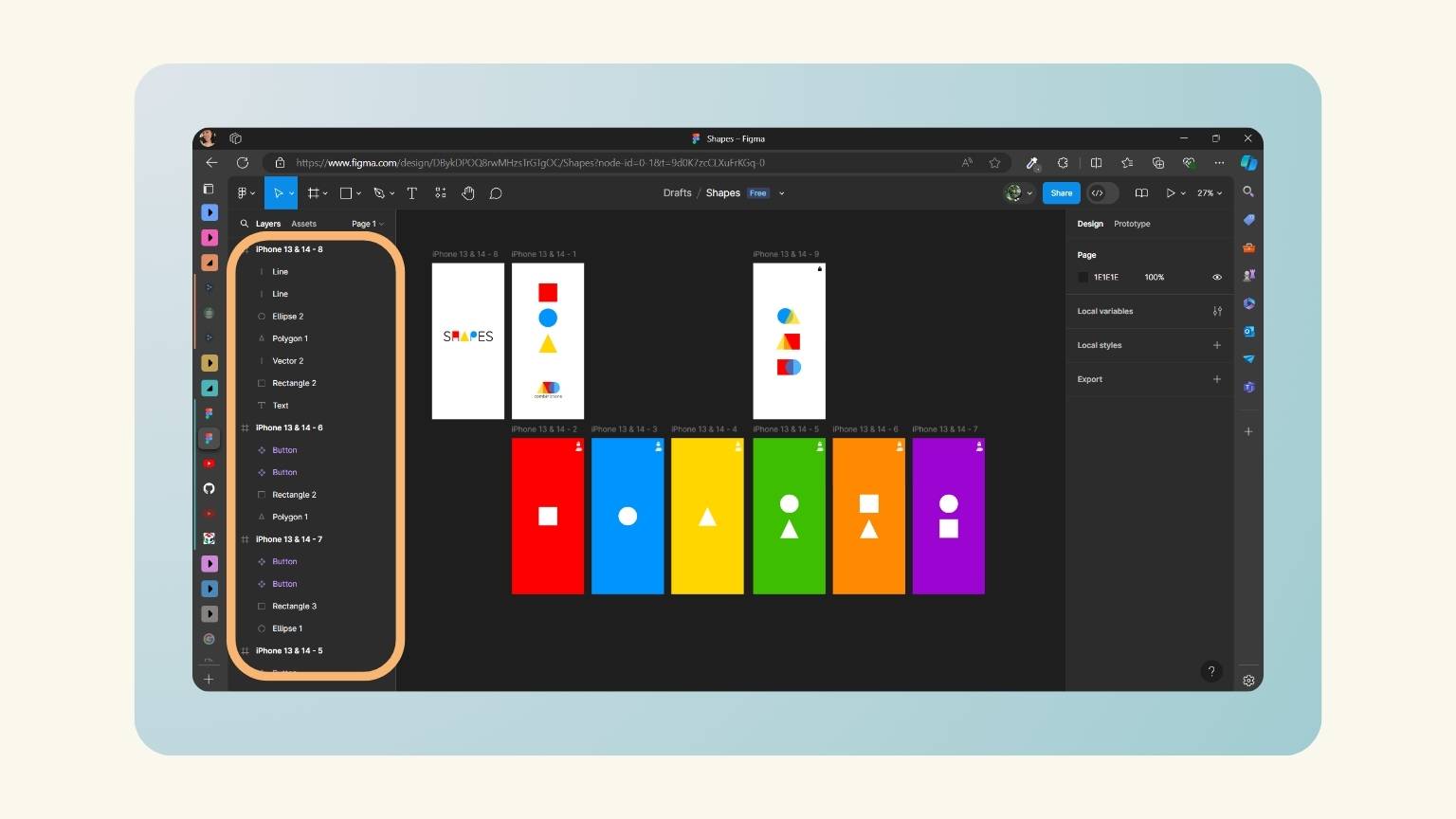
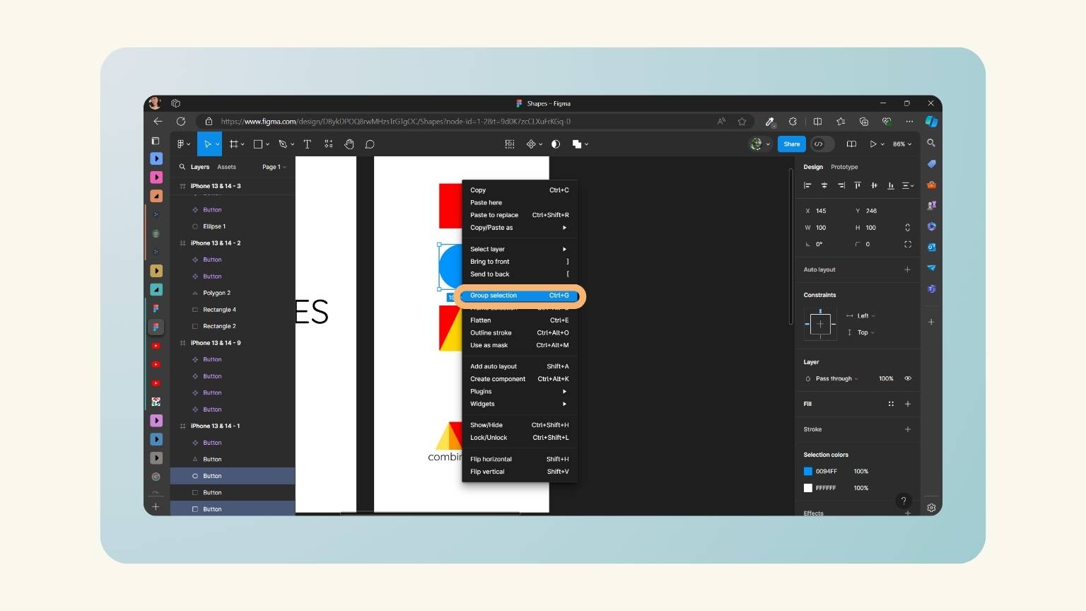
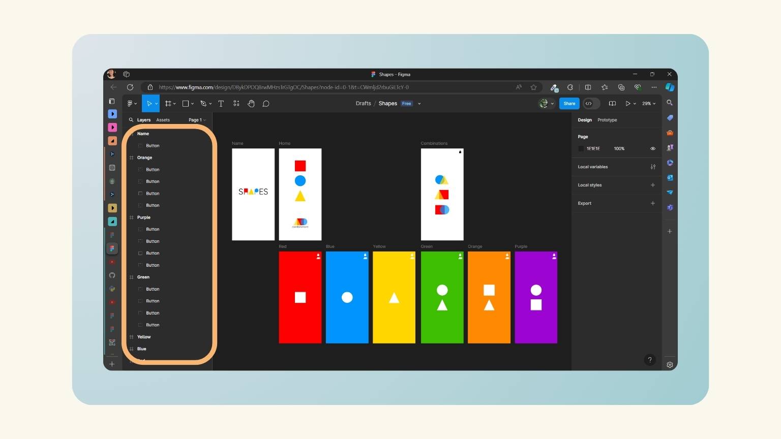
- I proceeded to rename the Figma elements, as the default options are not compatible with Tkinter Designer.
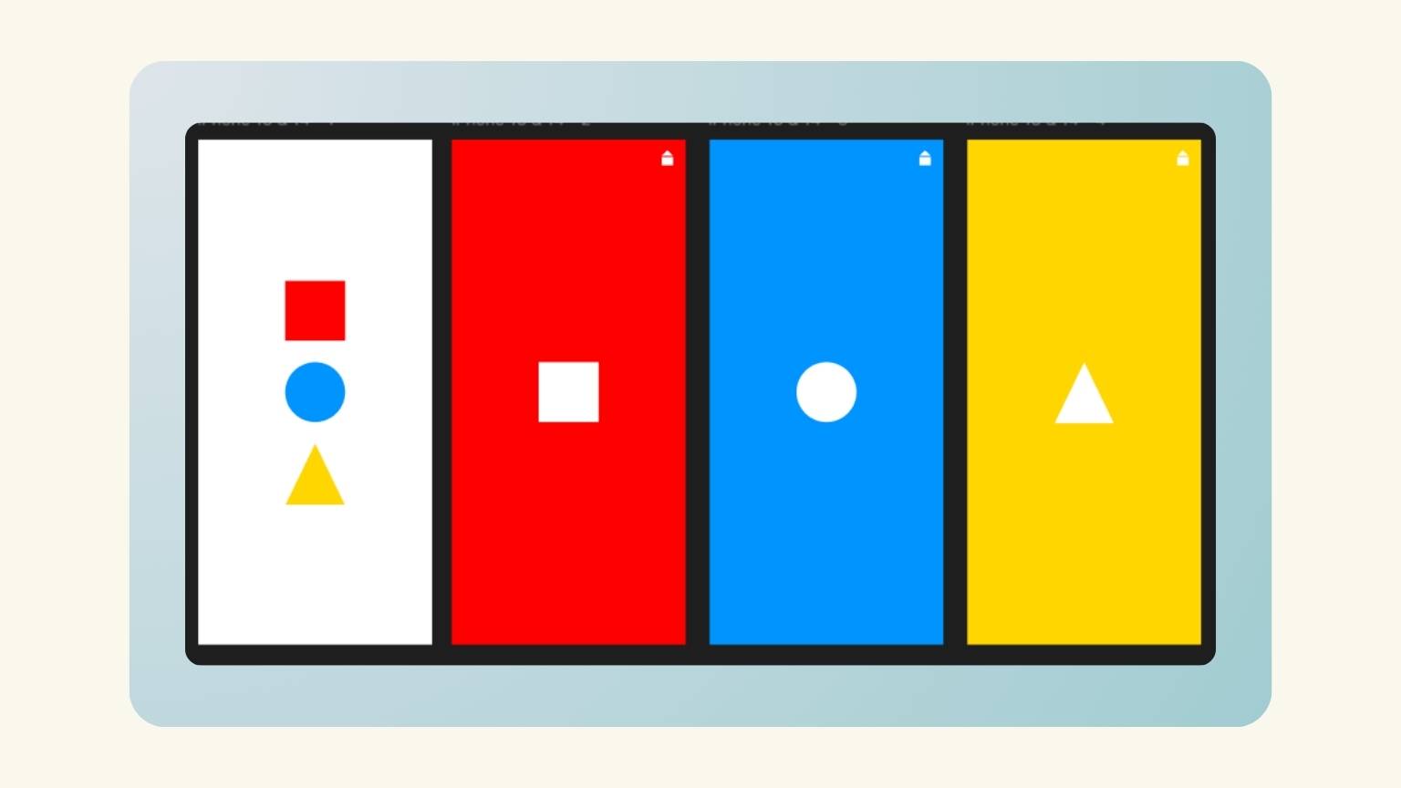
- Subsequently, I discovered that the elements I had converted as elements might not be displayed by Tkinter Designer. Consequently, I proceeded to modify them. To do so, I created a rectangle behind the figure.
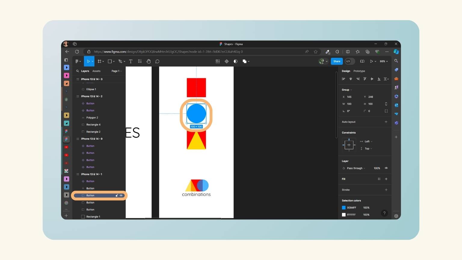
- I modified the color of the rectangle and the background so that only the desired figure is displayed. Then, I selected both elements to group them.
- I named the element as a button.
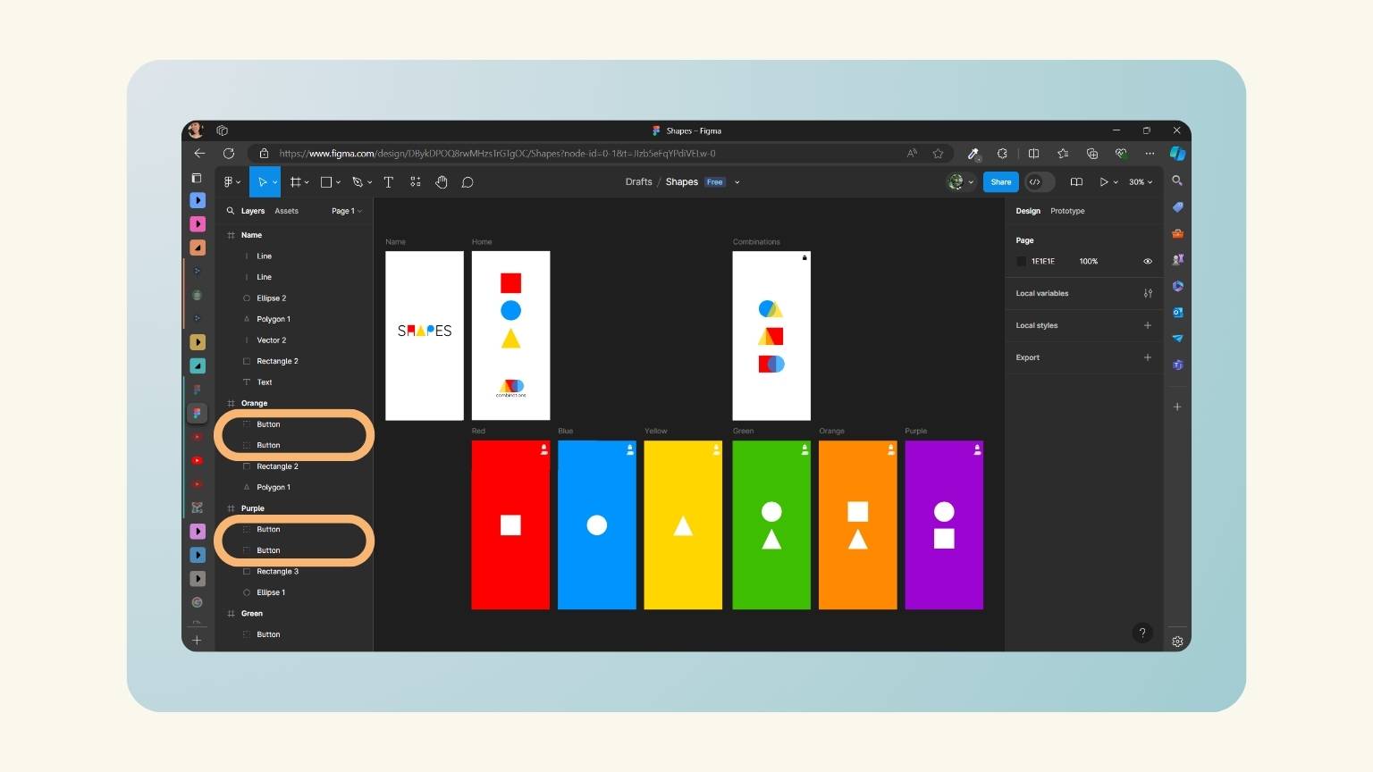
- I did the same with the others shapes.
- And this is how I designated the elements.
| Figma Element | Tkinter Element |
| Button | Button |
| Line | Line |
| Text | Name it anything |
| Rectangle | Rectangle |
| TextArea | Text Area |
| TextBox | Entry |
| Image | Canvas.Image() |
| ButtonHover (EXPERIMENTAL) | Button shown on hover |
… let's move to Tkinter-Designer
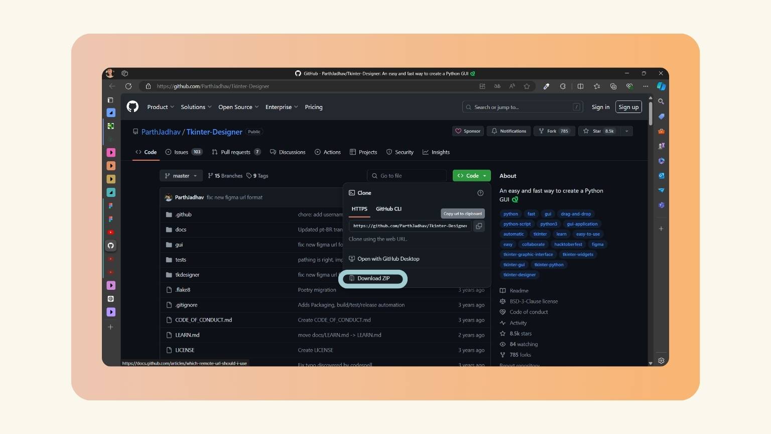
- I downloaded the ZIP file from the following link:
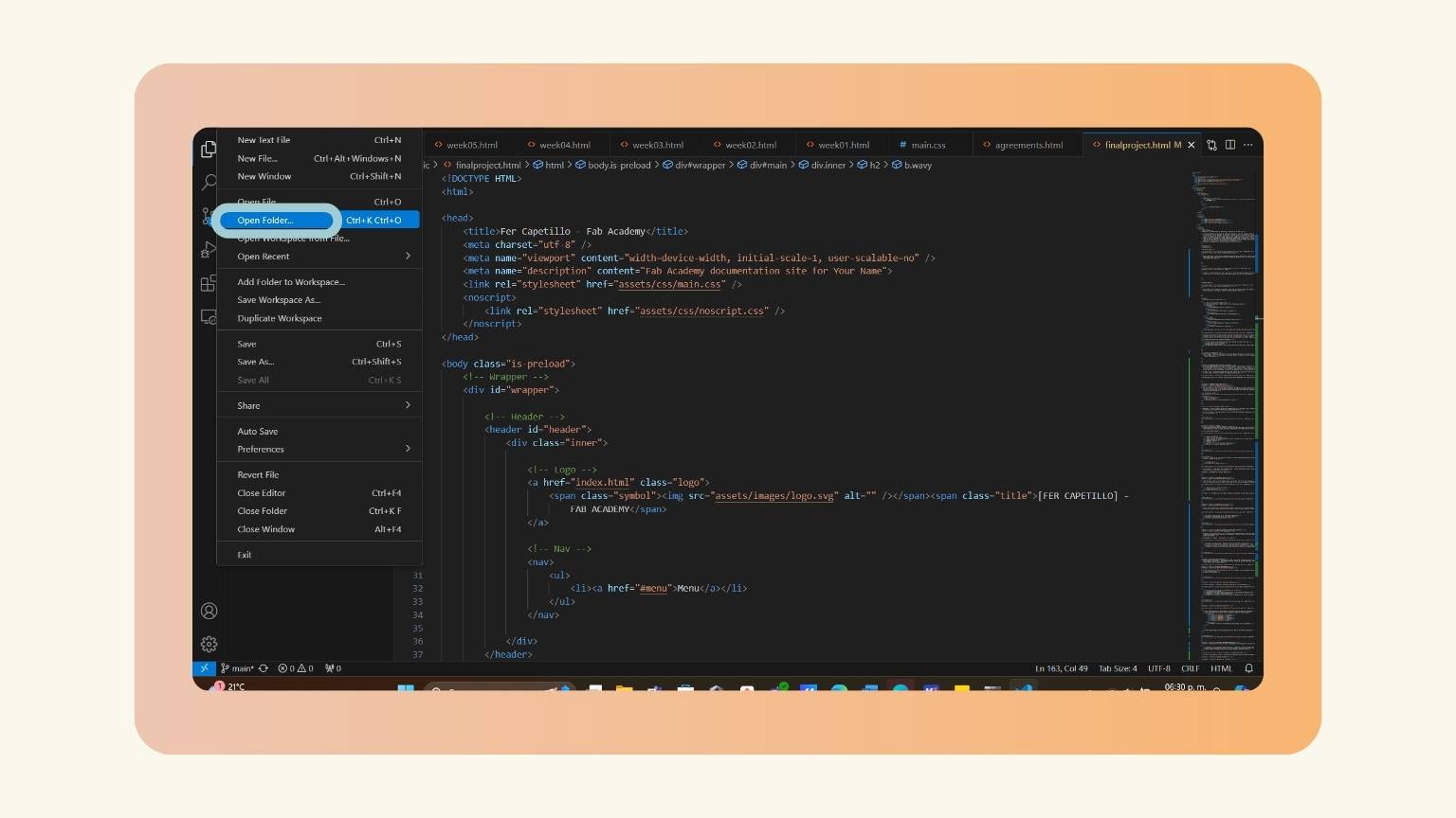
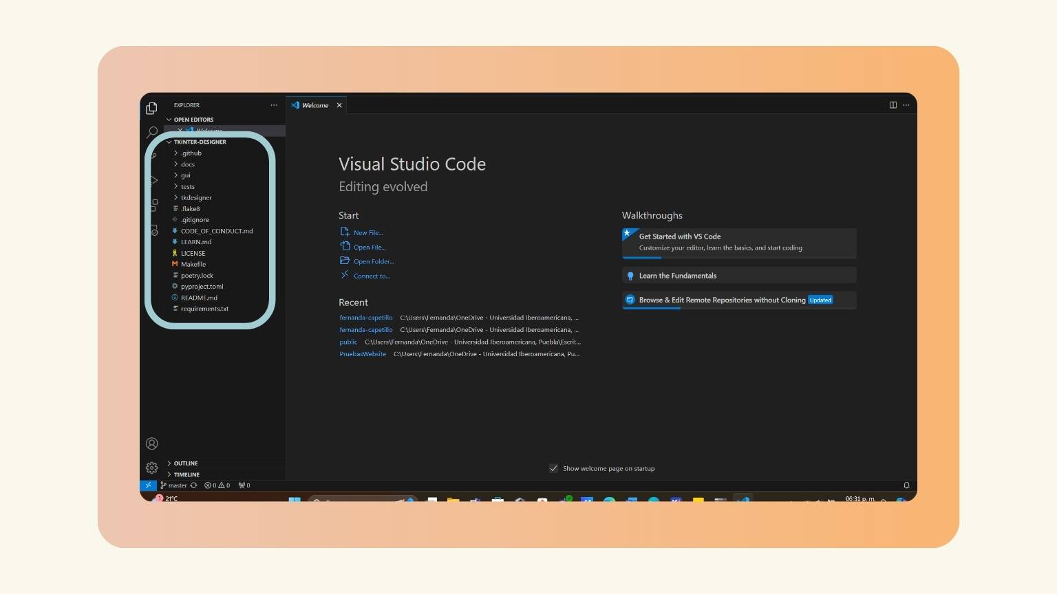
- Upon unzipping the archive, I proceeded to open Visual Studio Code in order to access the archive folder.
- The folder opened correctly.
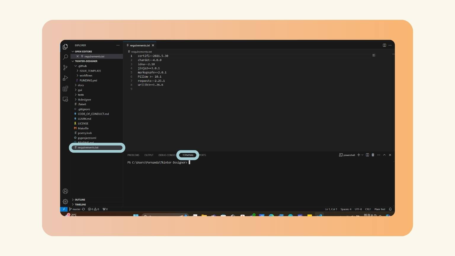
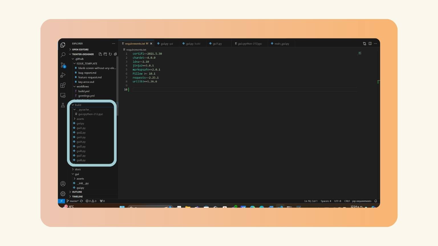
- I selected the file named 'requirement.txt' and opened the program terminal.
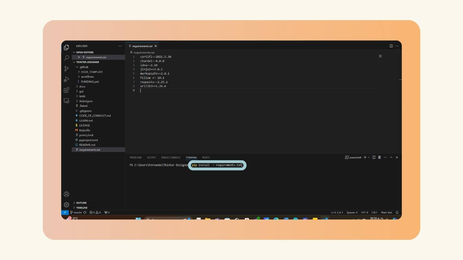
- I typed the following command:
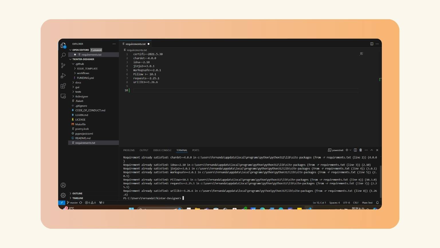
- The installation was successful.
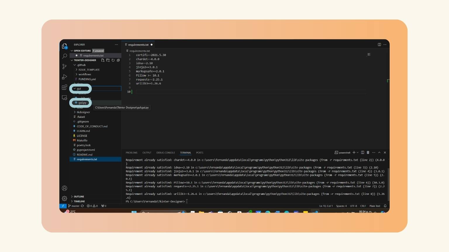
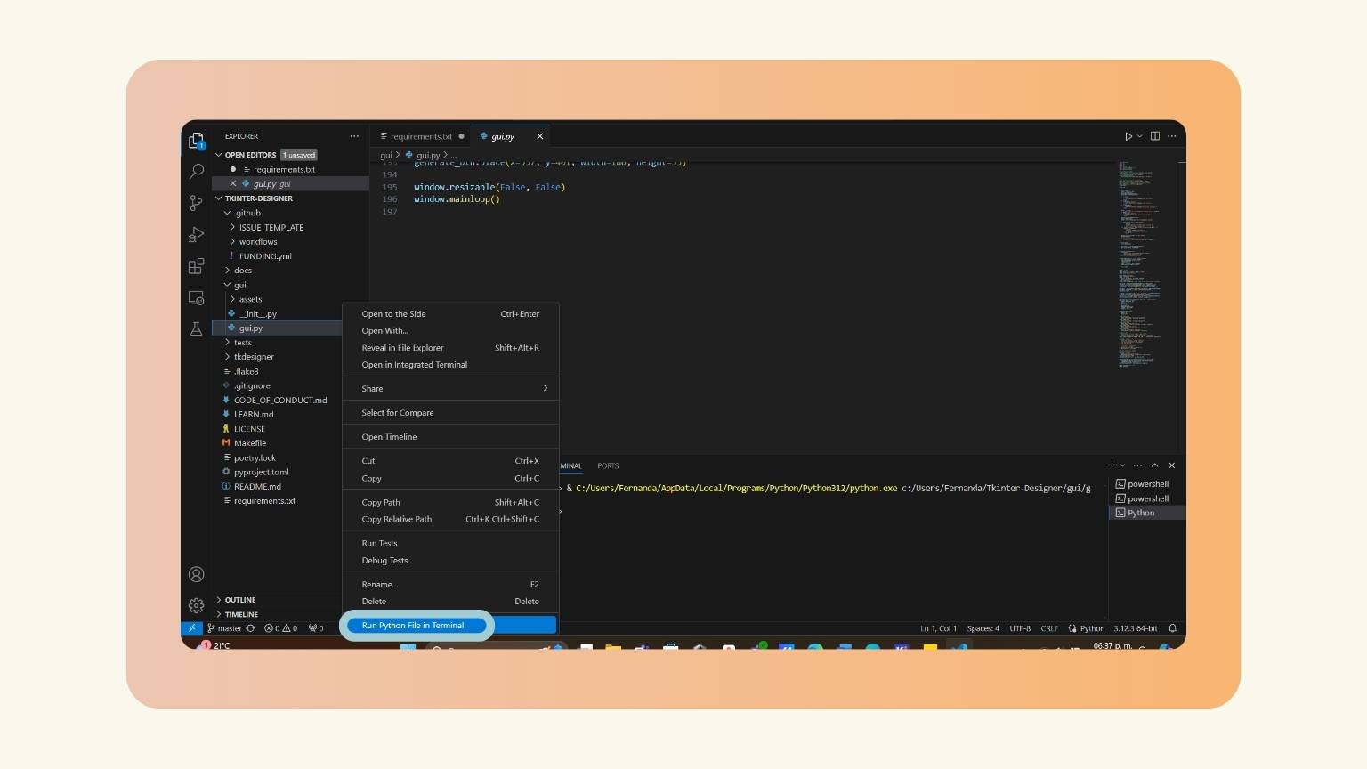
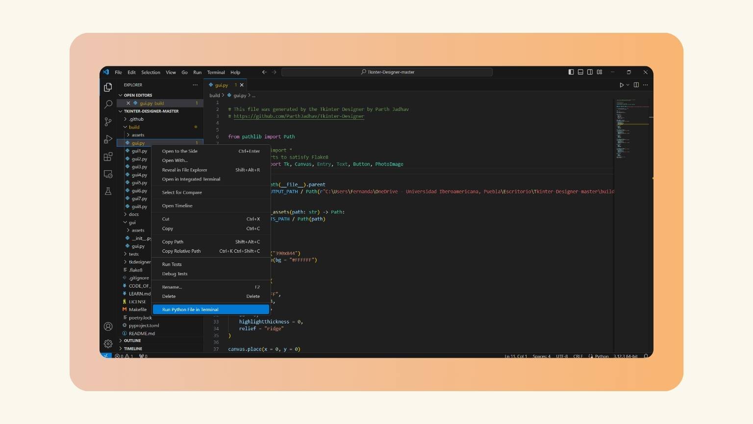
- Next, I went to the folder named 'gui' and specifically selected the file 'gui.py'.
- I right-clicked and pressed the 'Run Python File in Terminal' option.
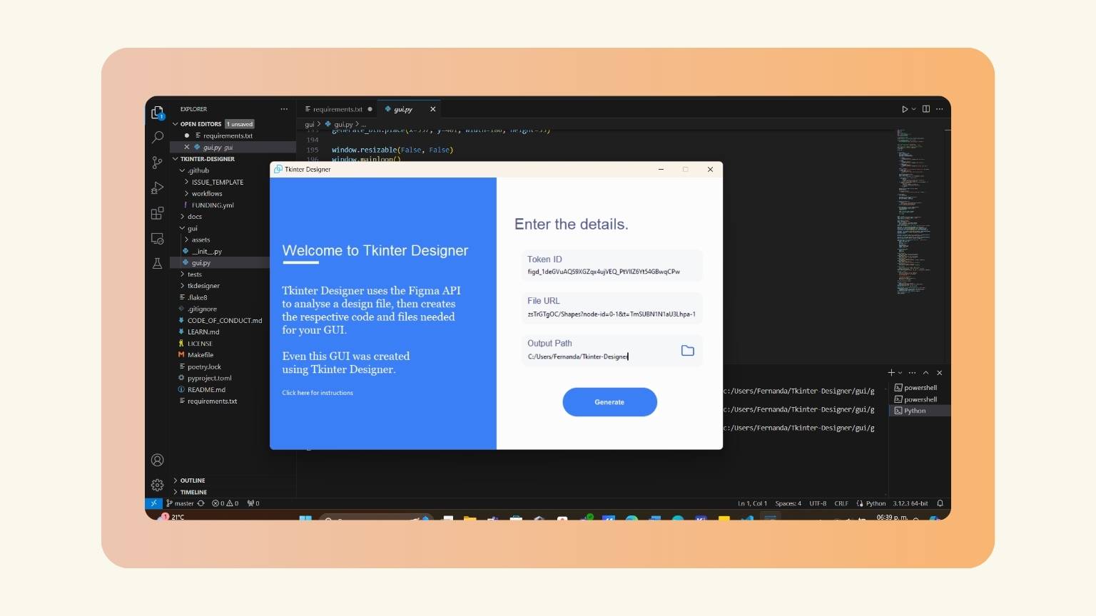
- The following menu opened:
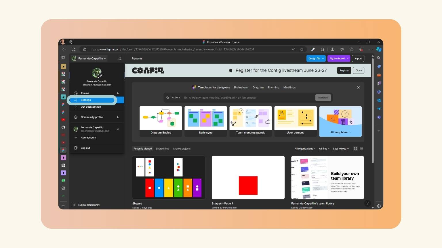
- I went back to Figma and went to my account settings.
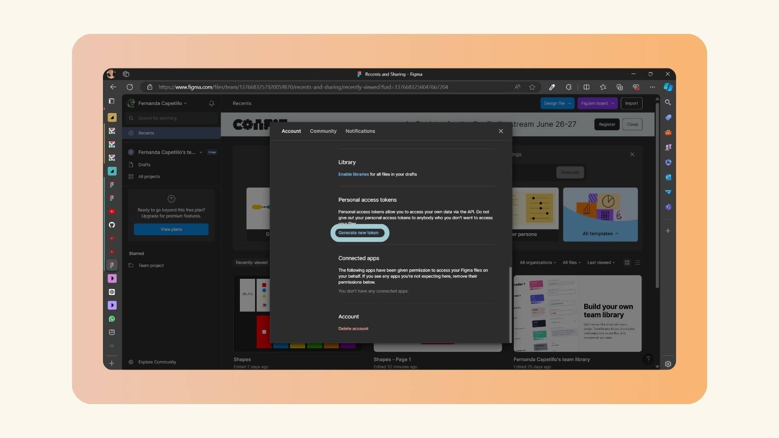
- I located the 'Personal access token' option and clicked on 'Generate new token'.
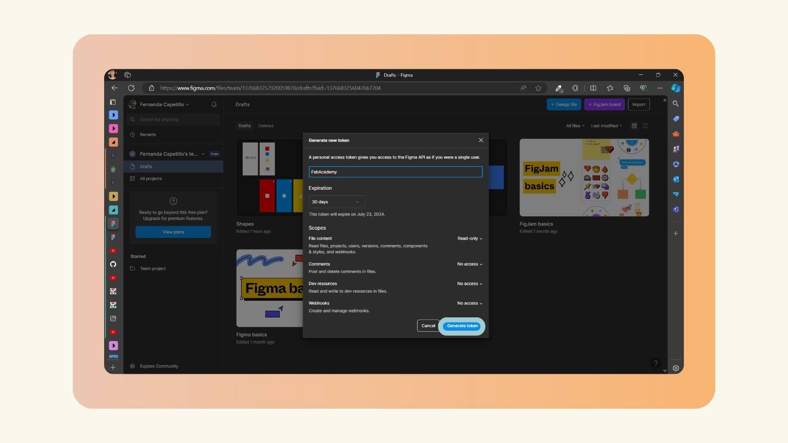
- I named the token and then generated it.
- Note: The token will only appear when you generate it, so the recommendation is to copy it and save it in a safe place.
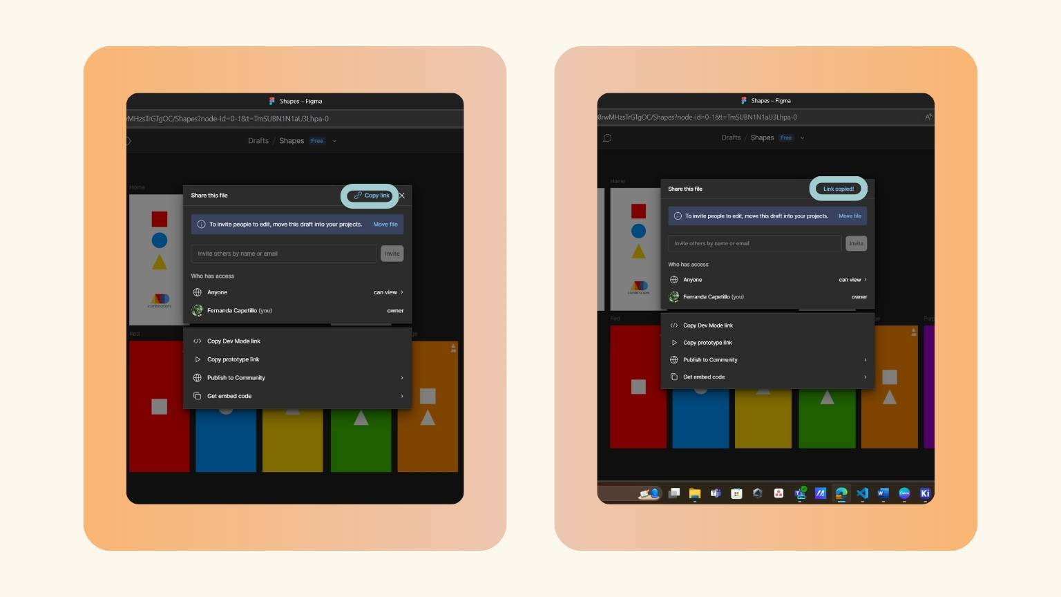
- Afterwards, I opened the design I made in Figma and went to the Share menu to copy the design link.
- I inserted the corresponding data in the Tkinter Designer menu.
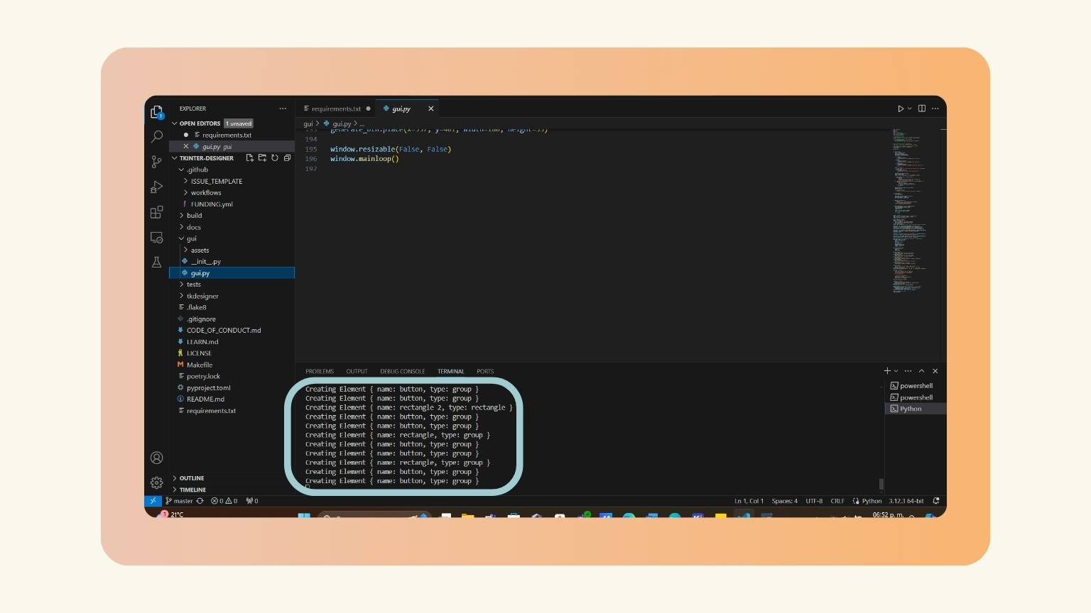
- The design was generated; to corroborate it, you can see the process in the Visual Studio Code terminal.
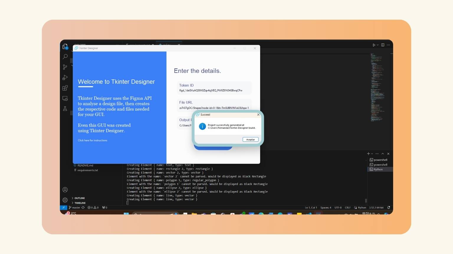
- As soon as the process is finished, this window appears.
- A folder designated "build" was created, and within this folder, the interface design was located.
- To confirm the successful transfer of the design, I selected the first file and initiated the "Run" function via the right-click menu.
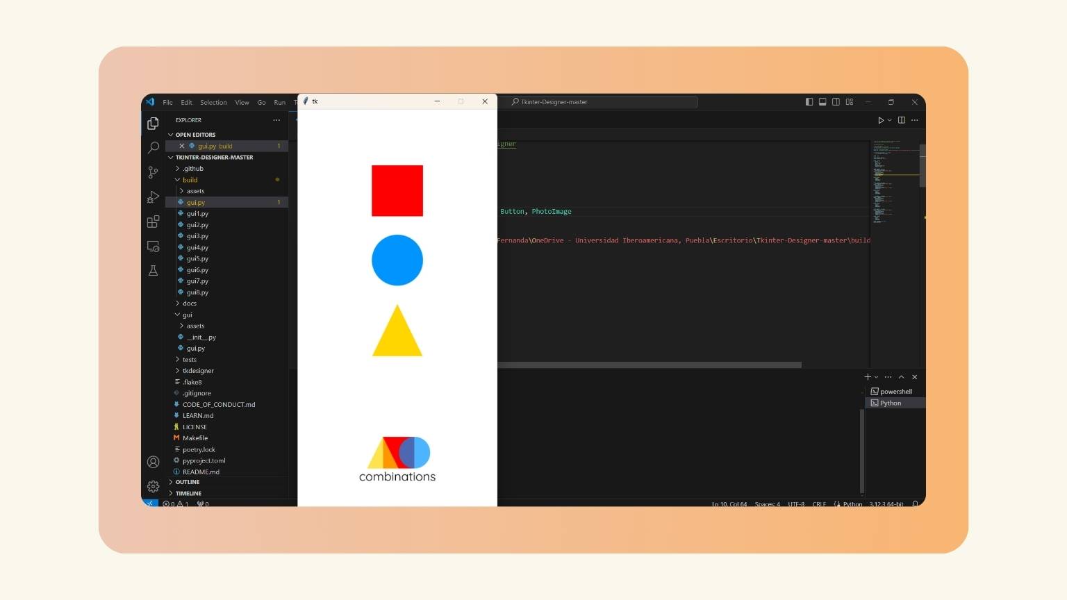
- The design was then opened, and the following was observed:
https://github.com/ParthJadhav/Tkinter-Designer
pip install -r requirements.txt

To fill in the requested data, I did the following:
Application Programming? I think yes
Once it had been confirmed that all the pages were in order, the next step was to begin the process of reconfiguring the code. The reconfiguration entailed integrating the requisite elements into the code to enable a XIAO LED to illuminate upon pressing a button within the interface.
So, what did I integrate into the code?
- First, I imported in the beginning the serial library
- I declared the variable ‘ser’.
- I made a serial object to open the appropriate serial port at a baud rate of 9600.
- The serial object lets you read and write to the serial port. Integrate a print statement to determine whether the port was successfully opened.
- I established an exception to investigate what occurs while attempting to open the serial port.
- When an error occurs, the message will be printed.
- In the event that the command fails, a message indicating that the connection failed will be displayed.
- I defined the toggle led function.
- I defined the variables ser and led_state.
- I added a condition that checks whether the variable ser is not None and the serial port is open.
- Then I anticipated the LED's initial status to be false or off.
- I set the LED's status so that it changes depending on whether it is true or false.
- I established the connection between the devices.
- I specified that if the condition is not satisfied, a message would be printed stating that the port is not accessible or open.
- I define the initial state of the LED as false.
- Then, I established the button function on the LED.
- I then opened Arduino and programmed the XIAO to accept information from the interface and switch on the LED. To do this, I loaded the following code:
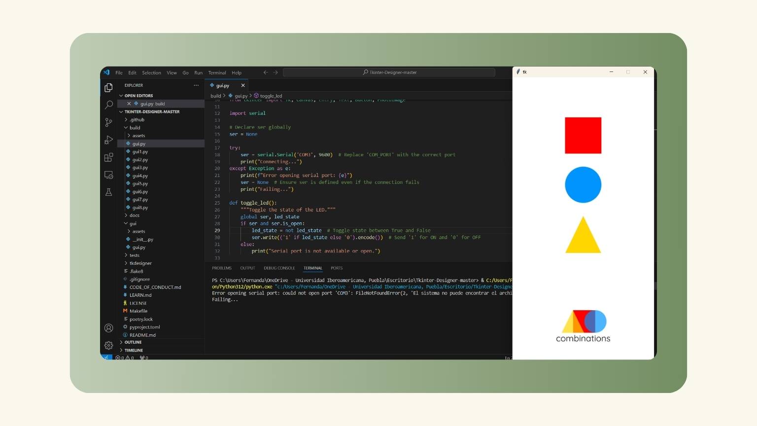
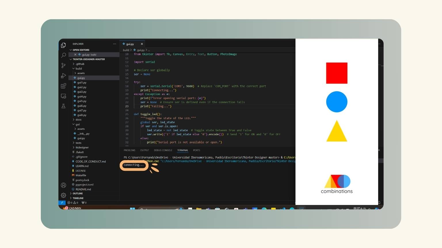
- I returned to Visual Studio to ensure that the button would do the operation on the board, but when I ran the Python terminal, I received the following error:
import serial
Error opening serial port: could not open port 'COM3': FileNotFoundError(2, 'El sistema no puede encontrar el archivo especificado.', None, 2)
						Failing...
... and the problems started
Now what?
I went to confer with a consultant about this matter, and after discussing it, we determined that the error is caused by an operating system limitation; therefore, we don't know for certain what it is.
So, before I gave up and completed it on a different device, I decided to repeat the entire process....
And it worked!
Result:
--- Extra ---
with neopixels:
Conclusion
This week was a 50/50 split between UI/UX design and PCB interaction. The former is an area of particular interest to me, as it presents a number of design considerations. The latter is also an area of interest, as it opens up a range of potential applications.
In conclusion, this week proved to be both instructive and rewarding. While the process of establishing communication between the interface and the PCB initially presented some challenges, the outcome is now satisfactory.