14. Networking & Communications
Protocols
UART Communication
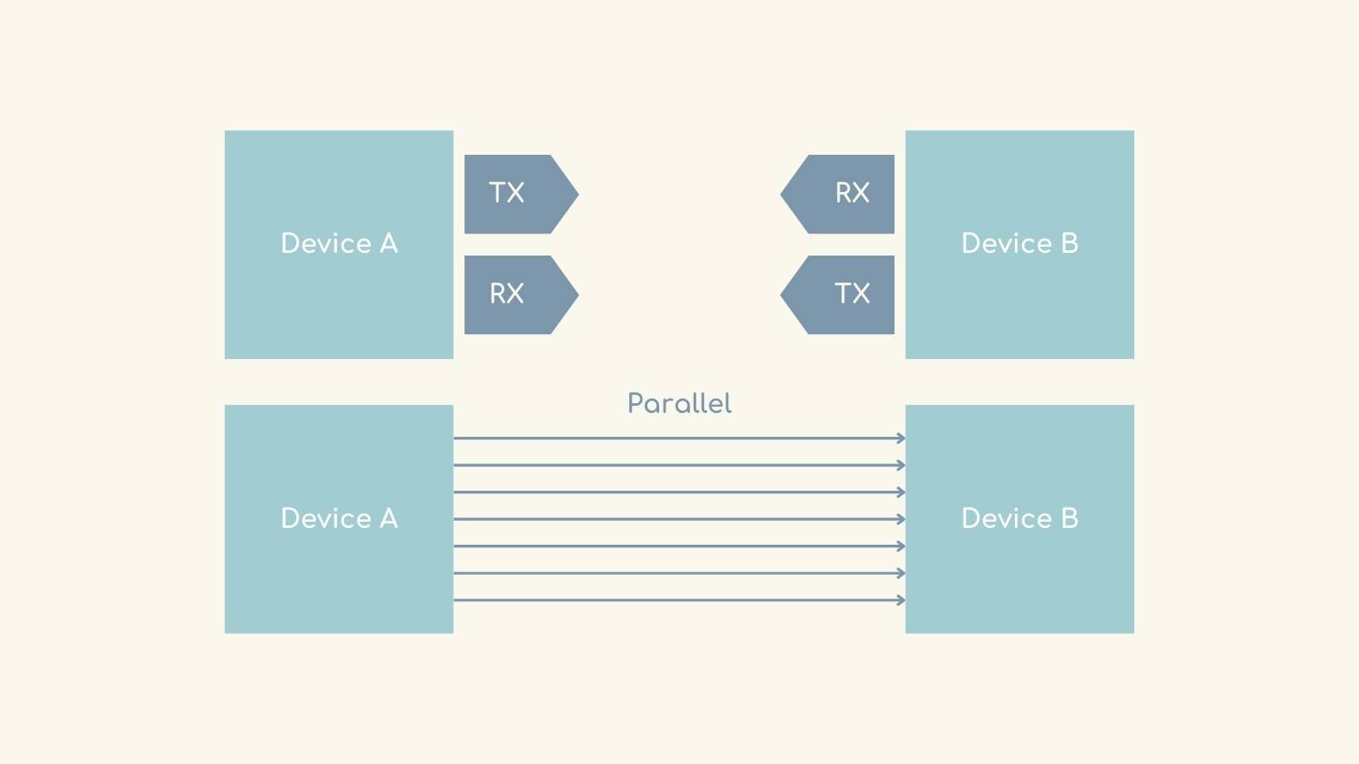
In UART (Universal Asynchronous Receiver / Transmitter) communication, two UARTs communicate directly. The transmitting UART converts parallel data from a control device such as a CPU into serial format, transmits it serially to the receiving UART, which also converts the serial data back into parallel data for the receiver. Only two wires are needed to transmit data between two UARTs. The data flows from the Tx pin of the transmitting UART to the Rx pin of the receiving UART.
UART communication can be simplex (one way), half-duplex (one side transmits at a time) or full-duplex (simultaneous transmission in both directions). Data is structured into frames for transmission.
An important point of UART is its asynchronous nature, which means that the transmitter and receiver do not share a common clock. Instead of a clock signal, the transmitting UART adds start and stop bits to the data packet being transferred. Both ends of a UART connection must use the same baud rate and frame structure to communicate effectively. In general, the advantages of the UART are in its simplicity and reliability for basic serial communication needs.
SPI Protocol
The Serial Peripheral Interface (SPI) protocol is a form of synchronous serial communication generally used for short-distance communication between microcontrollers, sensors and peripheral devices.
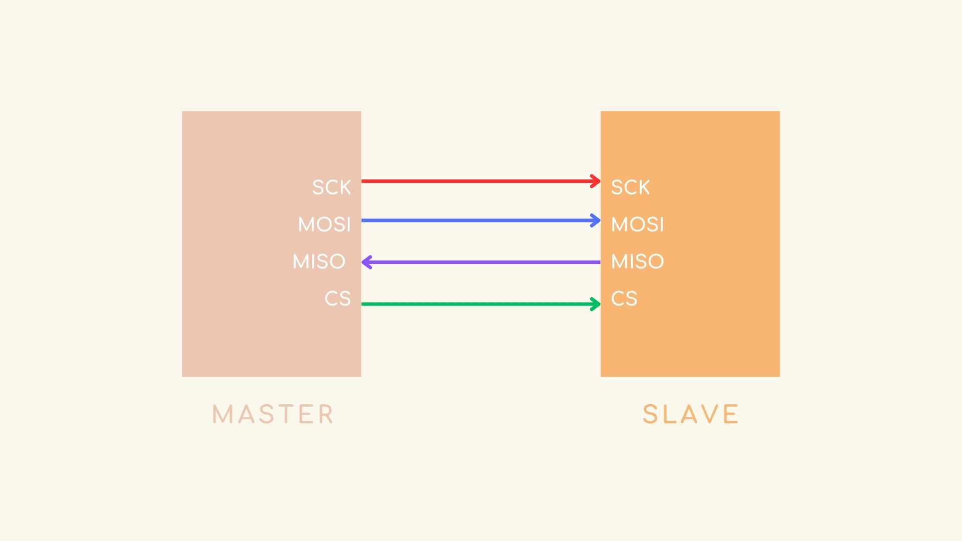
SPI operates in a master-slave configuration in which a master device initiates communication with one or more slave devices. The master device controls the clock signal and coordinates data transmission.
It normally uses four lines on the SCLK (Serial Clock) line to carry the clock signal generated by the master device and synchronise the data transmission between the devices. On the MOSI (Master Out Slave In) it transports the data from the master to the slave. On the other hand, MISO (Master In Slave Out) transports data from the slave to the master. And SS/CS (Slave Select/Chip Select): is used to select which slave device the master wants to communicate with, the line goes down to select a particular slave.
SPI supports full-duplex communication, in other words data can be transmitted in both directions (from master to slave and vice versa) using separate data lines (MOSI and MISO).
Data in SPI is transmitted in frames, usually 8 bits per frame, although different frame sizes can also be given depending on the situation and data.
I2C Protocol
Inter-Integrated Circuit, or I2C for short, is a popular serial communication standard. It lets devices that are near to one another or other integrated circuits on the same circuit board communicate with one another using just two bi-directional lines: Serial Data (SDA) and Serial Clock (SCL).
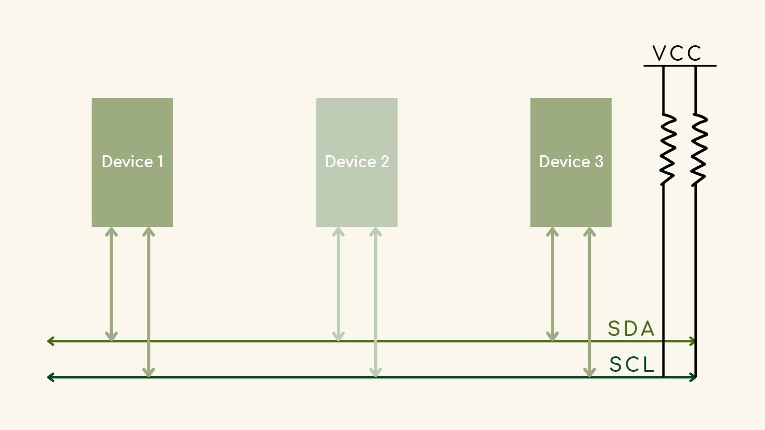
The protocol can function in either Master or Slave mode, with one or more Master devices controlling the flow and initiating communication and one or more Slave devices carrying out commands. I2C data transmission is organized into packets of nine bits, which include an address frame, data bits, and control bits for error handling (ACK/NACK). I2C has advantages over other protocols, including strong error detection through ACK/NACK signaling, cost-effectiveness, and multi-master capabilities, despite its slower speed.
I2C is appropriate for applications needing dependable, low-speed serial communication within constrained environments.
Group Assignment
Visit our group task by clicking on the button below.
What I did this week?
To make this week I decided to communicate this boards:
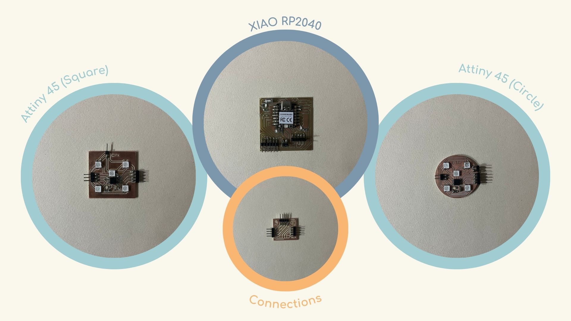
Note: It is important to note that each board requires unique programming.
Process
The following procedure was undertaken:
1. Test the boards
As a preliminary step, I verified the functionality of the boards. Subsequently, I utilized the Blink example to test the LED functionality on each board with the Attiny 45 microcontroller.
Circle PCB
Square PCB
Fortunately, both worked!
2. Protocol.. master and slave?
In order to facilitate communication between the boards, I elected to utilize the I2C protocol, as it necessitated the fewest number of pins for communication, and our instructors had indicated that it was the simplest to begin with and to comprehend.
3. New PCB to connections
Prior to initiating the programming phase, it became evident that a board was required to facilitate the requisite interconnections between the three boards. I designed the board with the intention of facilitating communication within the final project. Additionally, I included two resistors as a contingency measure.
The following steps were undertaken to create the new board:
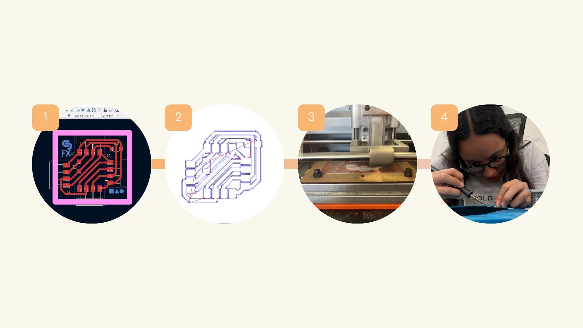
- The board was designed in KiCad.
- The requisite configuration was made in Mods for cutting.
- The board was cut.
- The necessary pins were soldered.
4. Programming
Tha master
- The program starts by setting up the button pin as an input and establishing serial communication for debugging.
- In the main loop, the button state is read.
- If the button is not pressed, a '0' is sent to address 8 and a '1' to address 9. A debugging message is printed to the serial monitor.
- If the button is pressed, a '0' is sent to the slave device with address 9 and a '1' to the slave device with address 8.
- A debugging message is printed to the serial monitor. A small delay is added to avoid button bounce.
Slave 1
- In setup()..
- This device is set as slave 1 with address 9.
- The receiveEvent function is called when data is received via I2C.
- The LED pin is set to output.
- Event handling:
- The receiveEvent is called when data is received from the master device.
- receiveEvent reads the incoming data.
- If the received data is '0', the LED is on.
- If the received data is not '0', the LED is off.
This code sets up a slave device with an I2C address of 9. The device listens for data sent by the master and controls an LED based on the received data.
Slave 2
- In setup()..
- The I2C communication is set to address 8, making this device a slave.
- The receiveEvent function is called when data is received via I2C.
- The LED pin is set to output.
- Event handling:
- The receiveEvent is called when data is received from the master device. Inside receiveEvent:
- The function reads the data..
- If the data is '0', the LED is on.
- If the data isn't '0', the LED is off.
This code sets up a slave device with an I2C address of 8. It listens for data sent by the master and controls an LED based on the received data.
The Result
Communication between two
(Master-Slave)
Communication between three
(Master-Slave-Slave)
Conclusion
I had anticipated that this week would be complex and somewhat chaotic. Nevertheless, I postulate that the apprehension I initially experienced was largely attributable to the sheer volume of information I was confronted with simultaneously, which ultimately led to a certain degree of confusion. However, once the protocol's operational principles are grasped, the subject can be more effectively contextualized for diverse applications.