10. Mechanical Design & Machine Design

Objetives:
- Design a machine that includes mechanism, actuation, automation, and application.
- Build the mechanical parts and operate it manually.
- Actuate and automate your machine.
Background
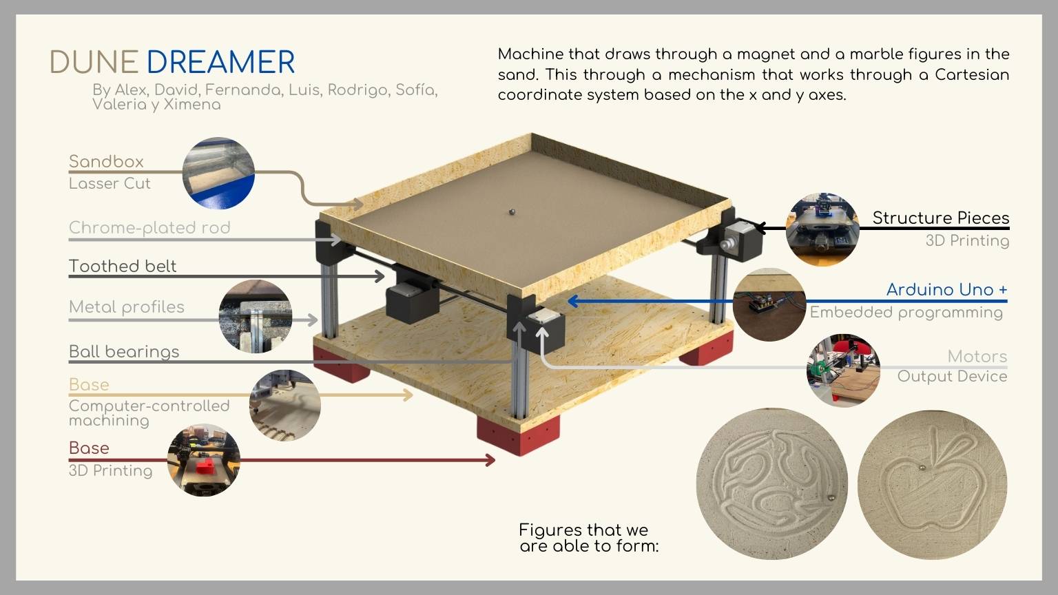
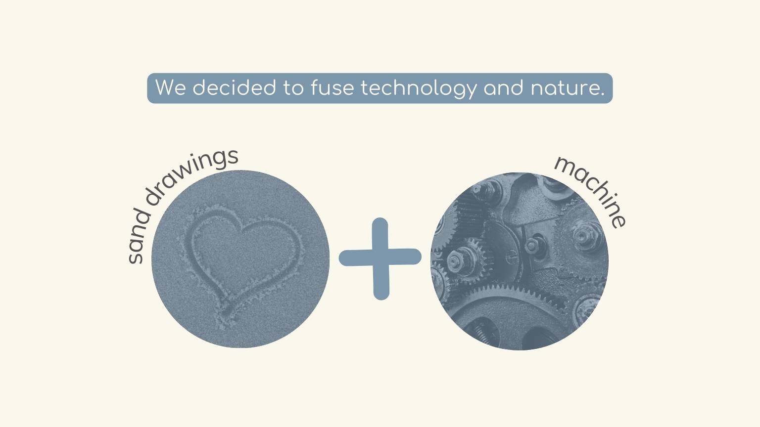
My team and I decided to create a machine that makes drawings in the sand.
So, imagine a machine designed specifically for creating intricate sand drawings. This machine combines elements of artistry and engineering to produce stunning, temporary works of art… It sounds amazing, right?
Group Assignment
Visit our group task by clicking on the button below.
But what did I do (or did we do) this week?
The first thing we did was define the theme with which we were going to approach the design of our machine.
I bet you've drawn pictures by the seashore after a long day at the beach, right? Pretty cool, huh? Well, we had the same idea, but we decided to take it up a notch and incorporate technology. We created an image with a metallic marble and made these drawings inside a box filled with sand.
To make more efficient progress, we decided to divide the team into two working groups:
- One focused on the design of machine parts.
- Another focus is on machine programming.
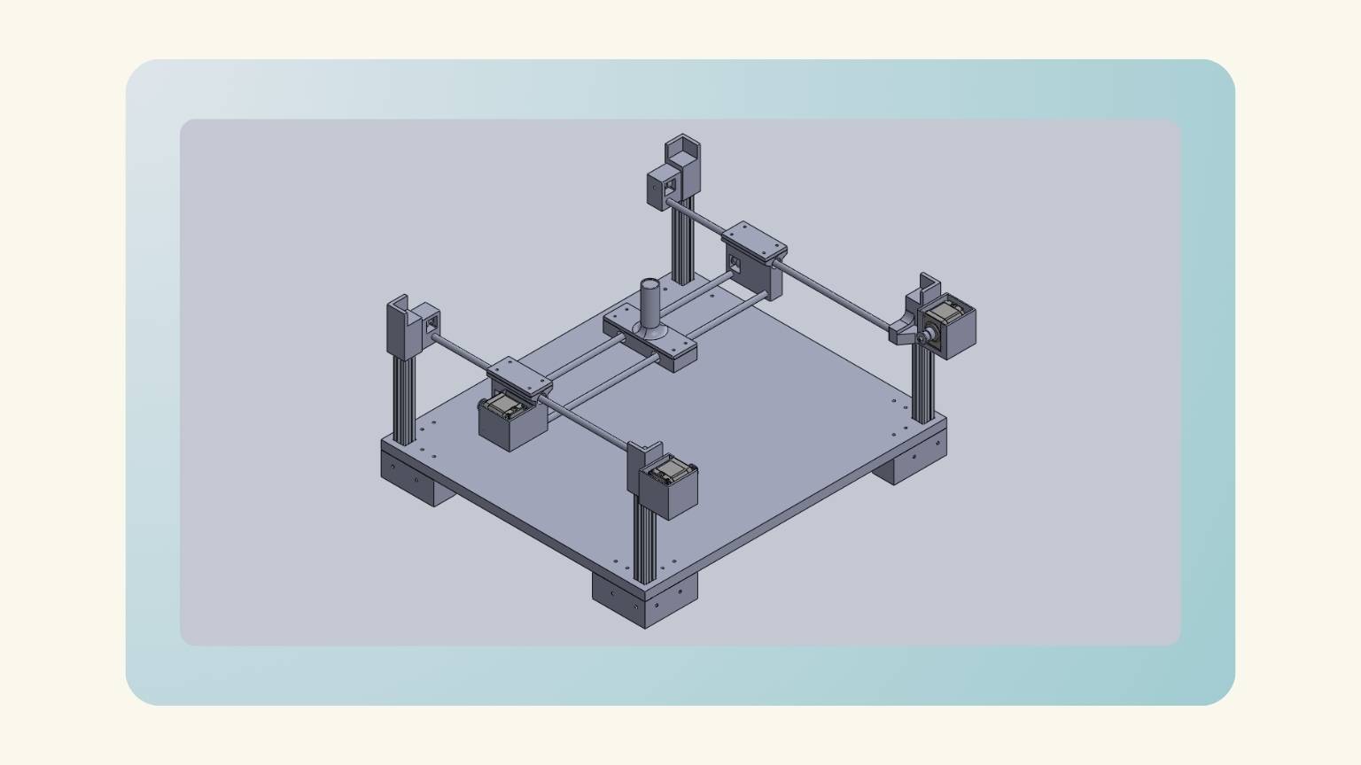
Design of machine
I was part of Team One. So, the team one design:
- Profile base.
- Band tension piece A.
- Band tension piece B.
- Acrylic Box.
- Belt clamping piece A.
- Belt clamping piece B.
- Motor support.
- Top support.
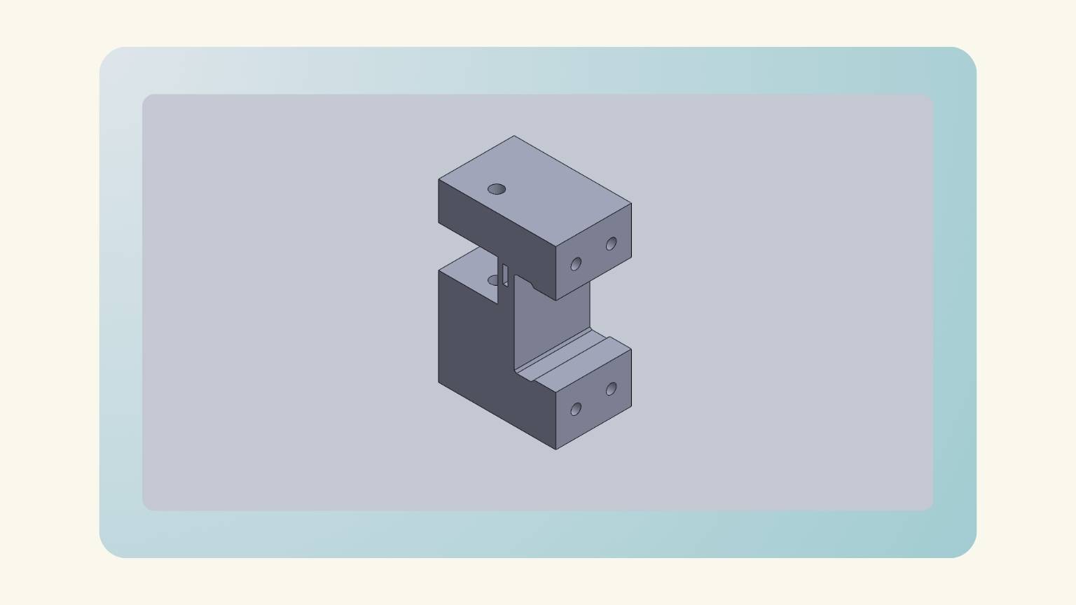
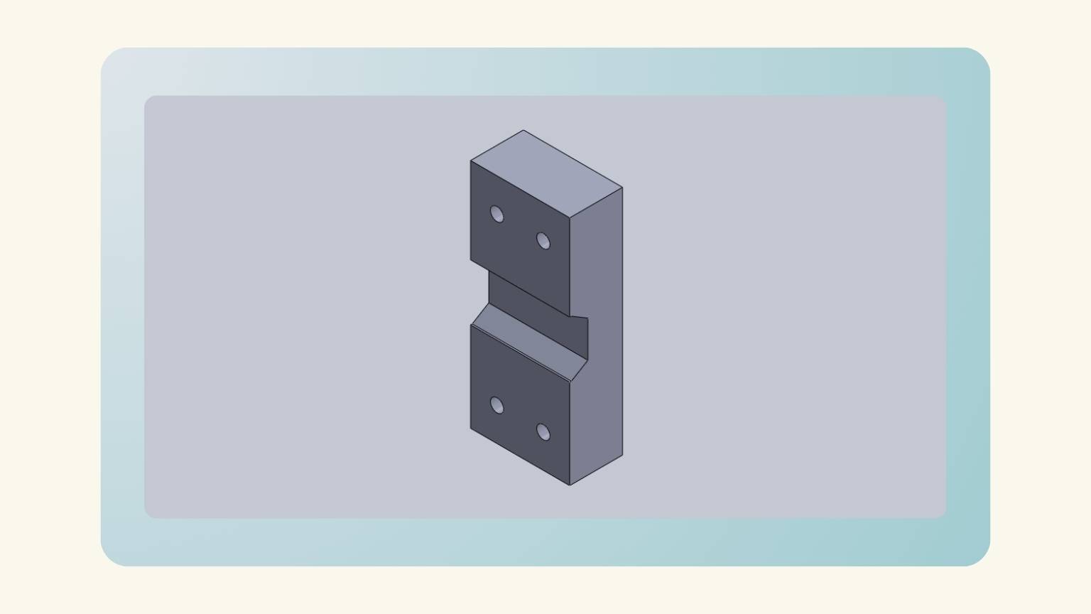
In my case, I was responsible for designing two pieces:
Band tension piece A
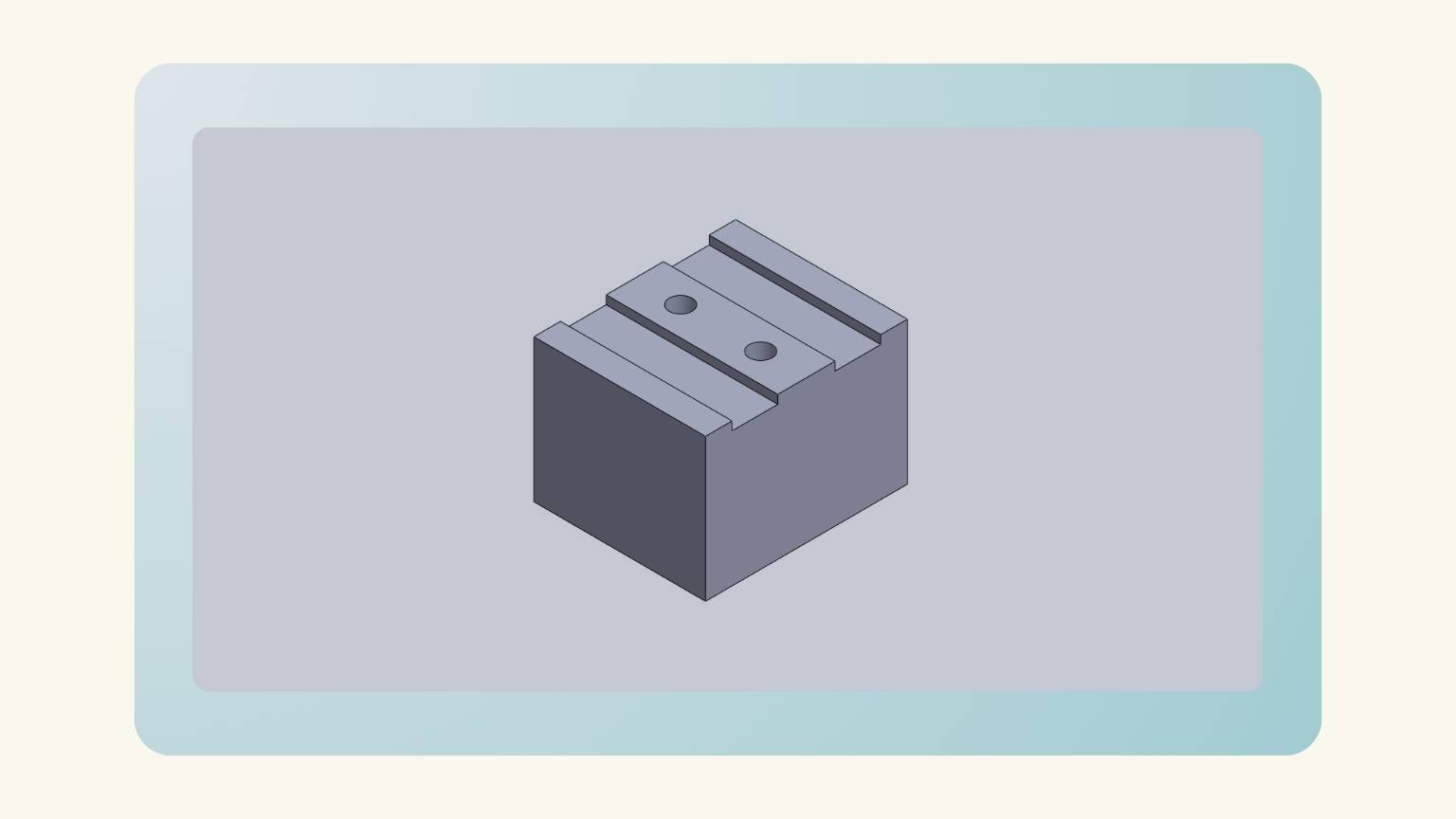
Band tension piece B
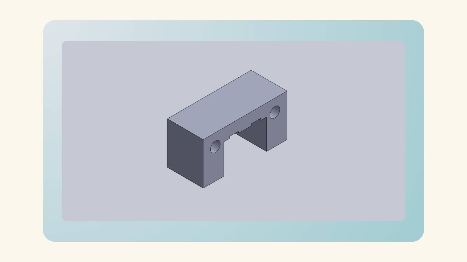
Then, I redesigned the belt clamping piece A and B according to the measurements and design of the pieces that I designed:
Redesign
Then, we must redesign the machine. So, we redesigned the pieces, and there are the new parts:
- Profile base.
- Motor support.
- Top support (for tooth belt).
- Centerpiece for the magnet.
- Side piece for movement A.
- Side piece for movement B.
- MDF Box.
- Lid for side parts.
- Tape A.
- Tape B.
3D Printing
Recap
The machine used for the 3D printing was...
Ender 3 S1 PRO
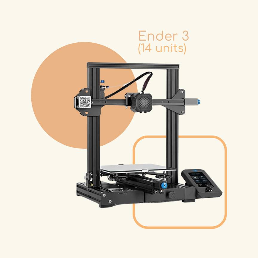
Ender 3 printers are popular in the 3D printing industry due to their cost and dependability, making them ideal for both beginners and professionals. They are adaptable, easy to use, and suitable for a variety of printing jobs.
Characteristics:
- Printing Technology: FDM
- Build Volume: 220 x 220 x 270 mm
- Printing Speed: 150 mm/s
- XY resolution: ± 0.1 mm
- Layer Height: 0.05 - 0.4 mm
- Nozzle Temperature: Up to 300° C
- Supported Materials: PLA, ABS, PETG, TPU, PA, WOOD
We printed theses pieces:
First Design
- Profile base.
- Band tension piece A.
- Band tension piece B.
- Acrylic Box.
- Belt clamping piece A.
- Belt clamping piece B.
- Motor support.
- Top support.
Redesign
- Profile base.
- Motor support.
- Toothed belt feed-through.
- Centerpiece for the magnet.
- Side piece for movement A.
- Side piece for movement B.
- Lid for side parts.
- Tape A.
- Tape B.
We used these parameters:
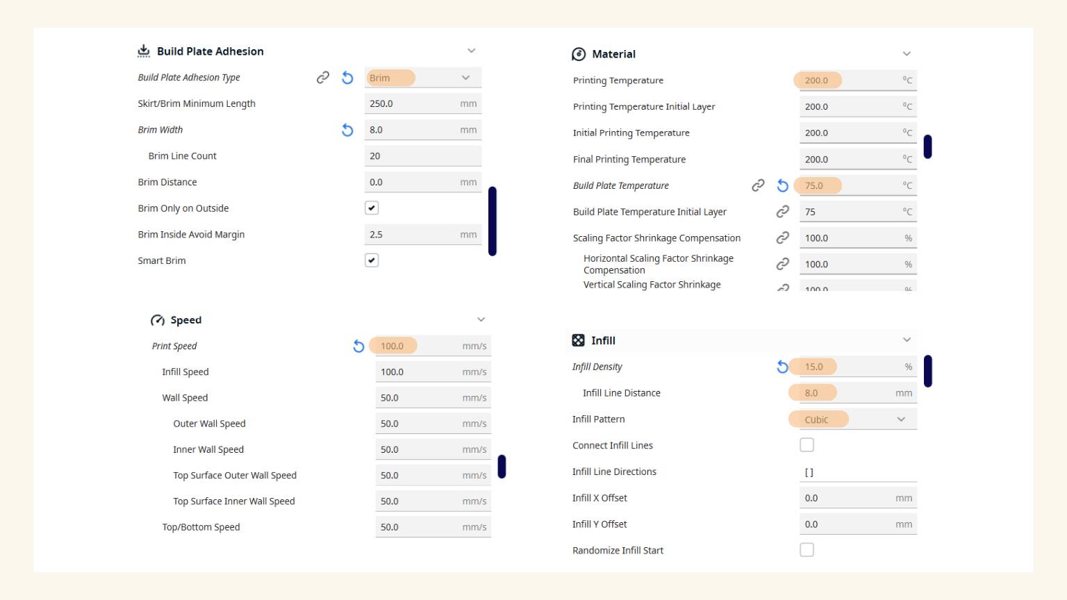
This was the process:
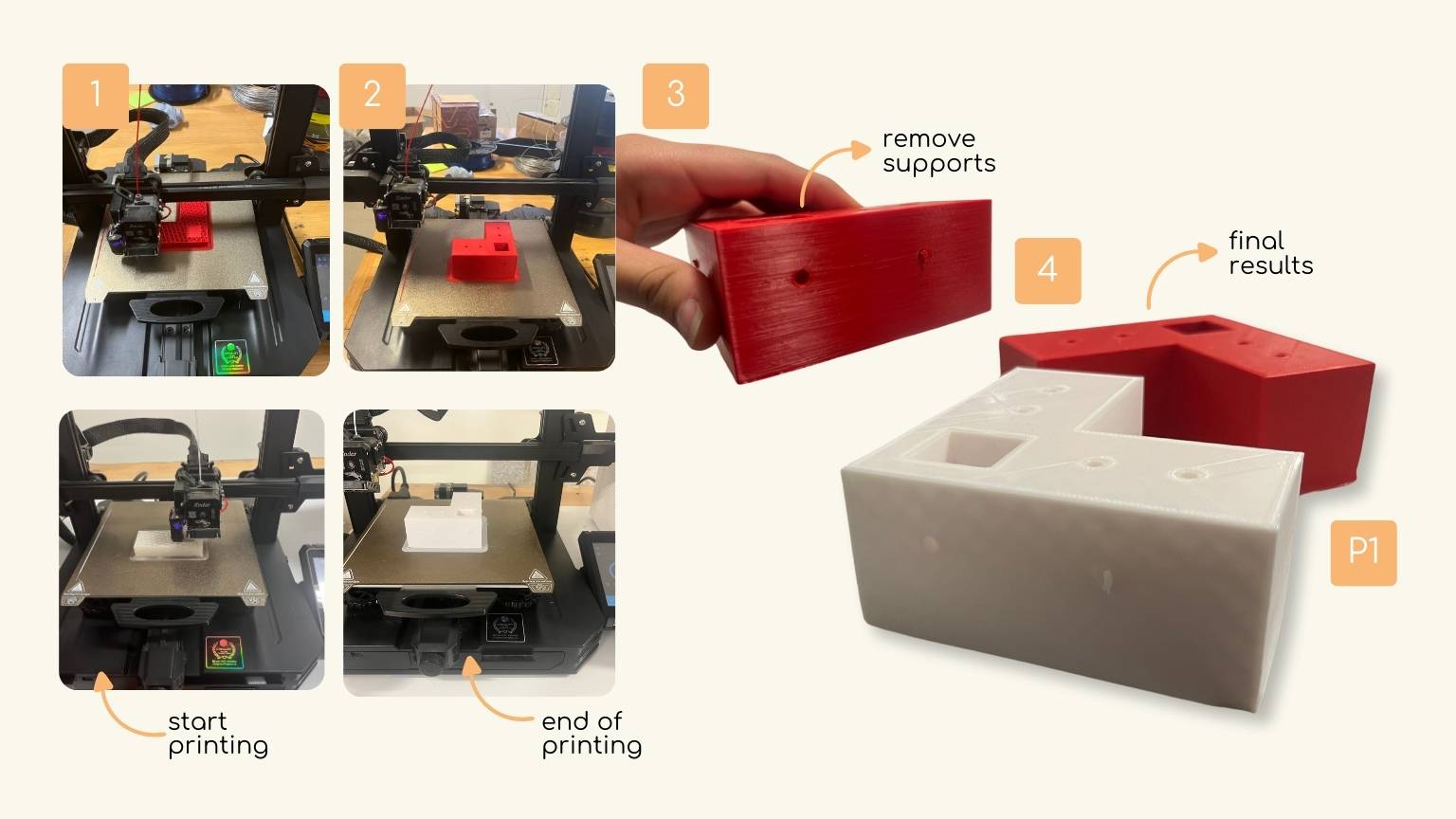
Note:
P1. First part of the first design and redesign.
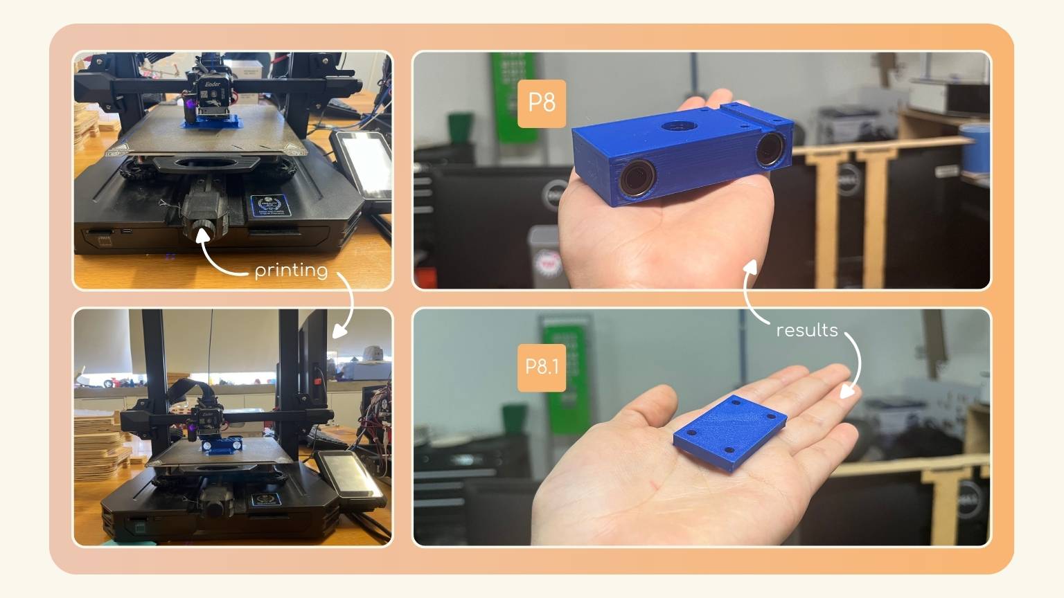
Note:
- P8. Eighth part of the first design.
- P8.1. Eighth first part of the first design
We made these mistakes:
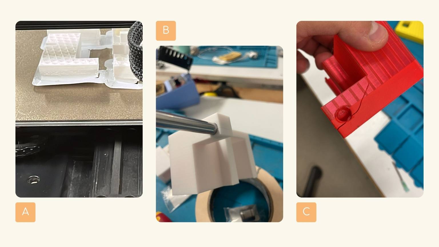
Note:
- A. Print lifting.
- B. Wrong dimensions and designs caused breakage.
- C. More broken parts.
The results:
Note:
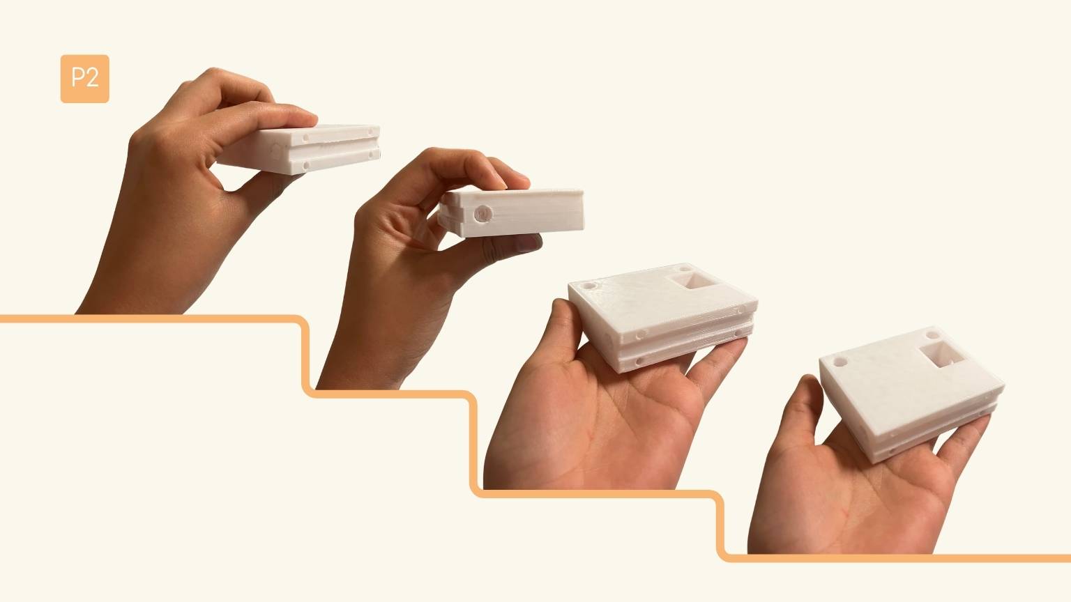
P2. Second part of the first design.
Note:
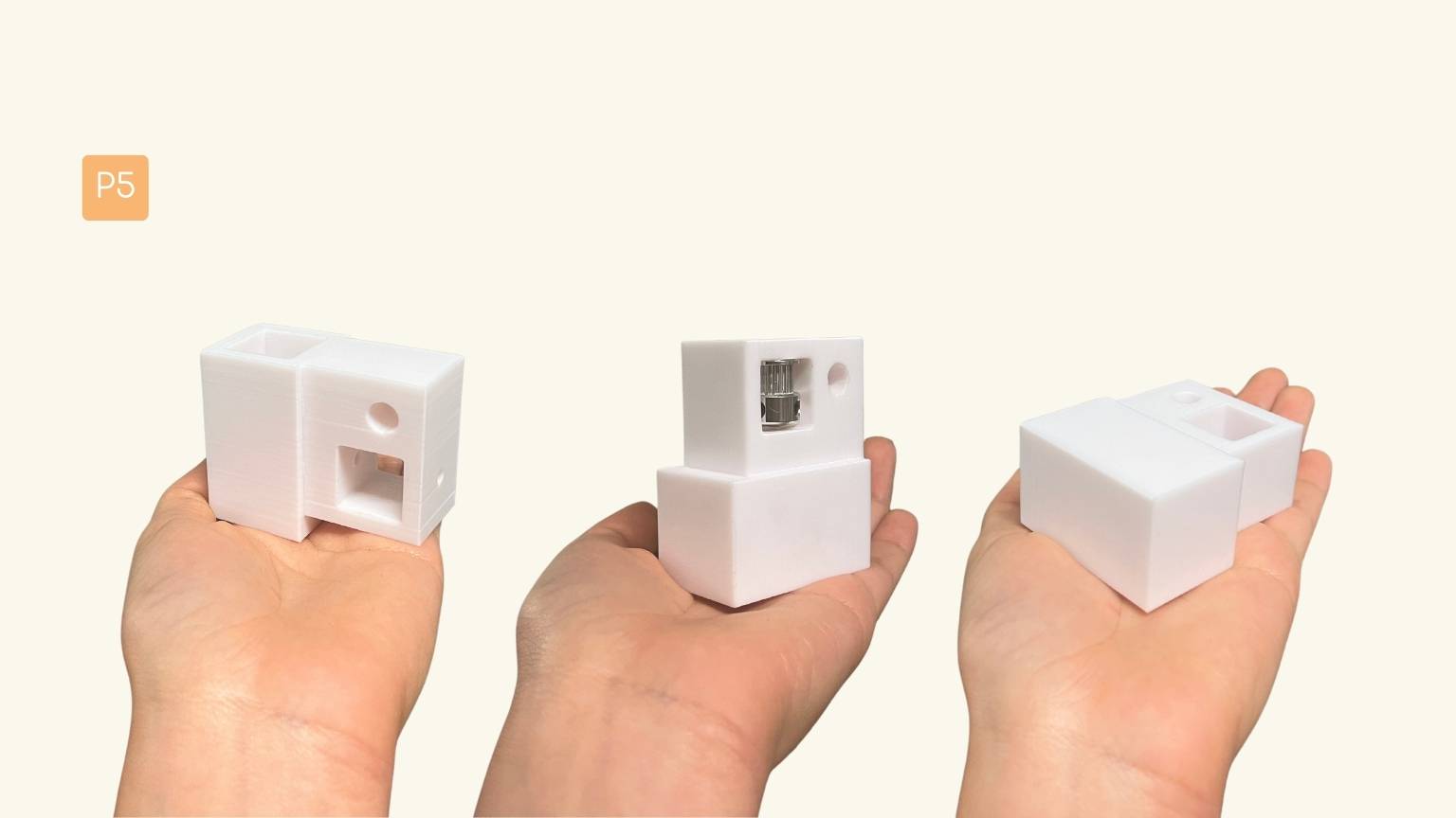
P5. Fifth part of the first design.
Note:
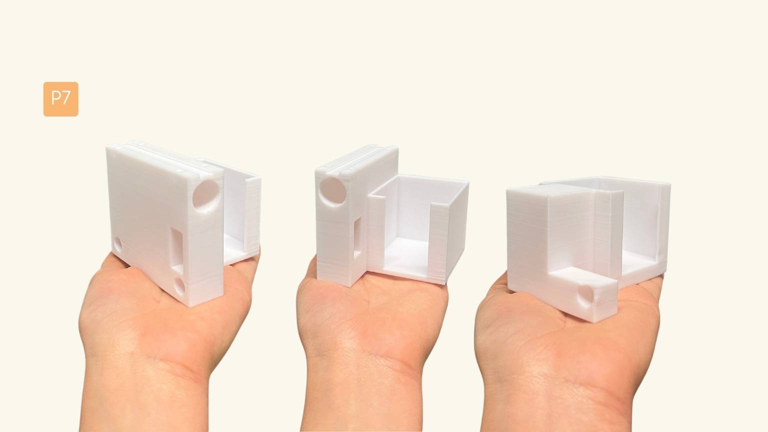
P7. Seventh part of the first design.
Note:
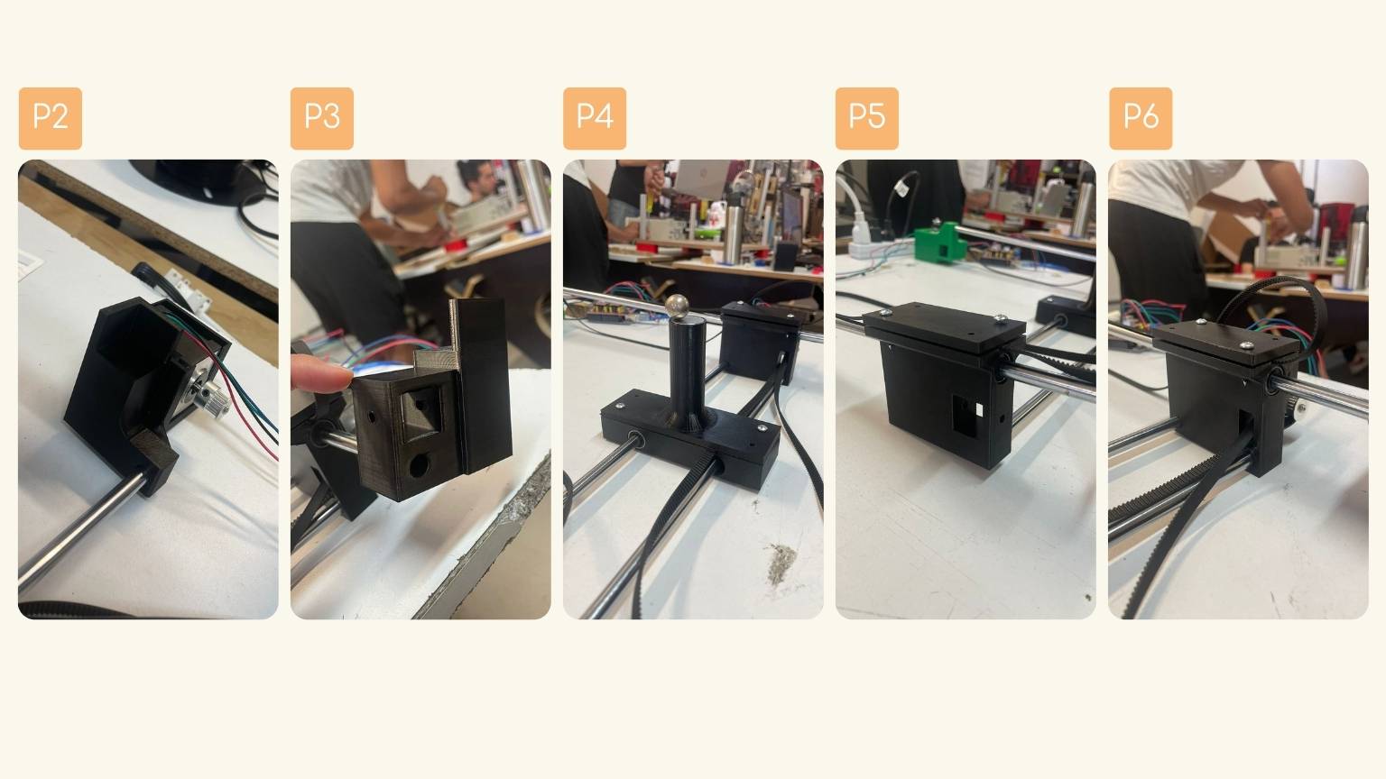
- P2. Second part of the redesign.
- P3. Third part of the redesign.
- P4. Fourth part of the redesign.
- P5. Fifth part of the redesign.
- P6. Sixth part of the redesign..
New learning!
Calibrate the machine
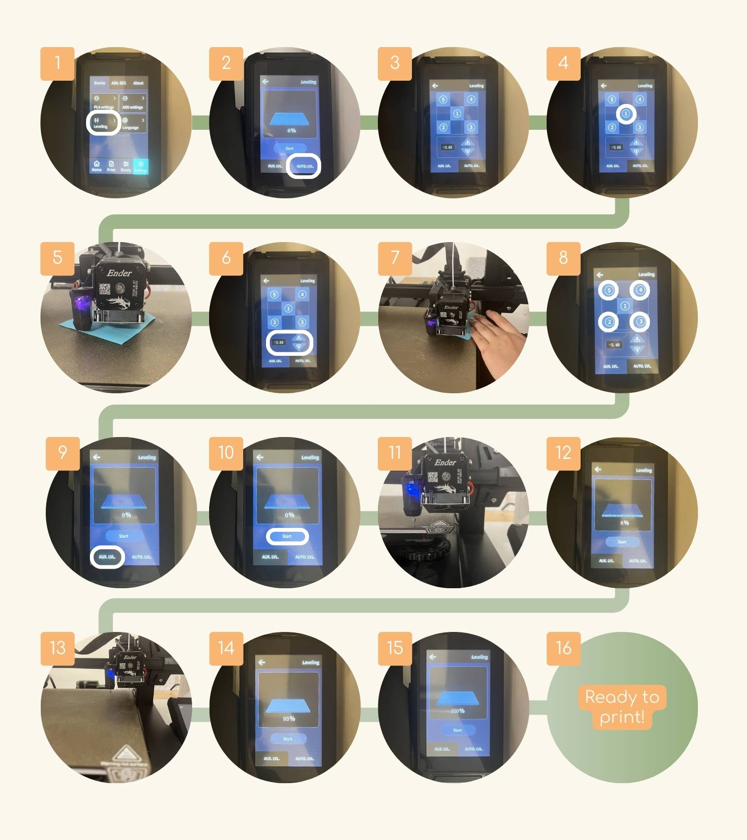
I learned how to calibrate the machine manually! Here I show how to do it:
- In the section of ‘Settings’, you select the ‘Leveling’.
- This menu appears, where you must select 'AUTO.LVL.’.
- You will see this menu on the screen.
- Then click on the number one to start calibrating the machine, starting from the center.
- The extruder will be directed towards the center, and you should place a piece of paper underneath it in order to calibrate the machine with the paper technique.
- To adjust the height, you can use the lower section shown on the screen or the pins on the individual corners of the print bed to adjust the height.
- Note: Once you have modified point one, it is recommended to adjust the others with the bolts.
- Move the paper to check how much friction is generated, and once you reach a high level of friction between the extruder and the bed, you will have calibrated that point well.
- Continue with the next four points.
- Once you have calibrated each point, go back to the ‘Leviting’ main menu and click on 'AUX.LVL.’.
- Press ‘Start’.
- The computer will start to calibrate automatically.
- You will see the process on the menu.
- The machine finished calibrating the last reference point.
- In this poiny, the calibration is 93%.
- The calibration is 100%.
- It will be ready for printing.
Assembly
With the help of equipment, I was assembling the pieces that were coming out of the 3D prints to determine if they fit together or if it was the case that they were optimal for the fit of the elements that were not designed, for example, the chrome rods.
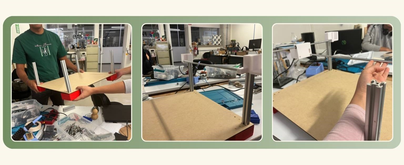
In this way, we were making the necessary corrections for a good assembly of all the elements.
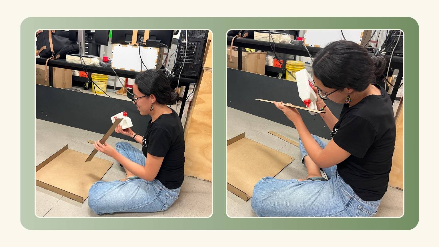
On the other hand, I made the gluing of the first box that would contain the sand; this was made with 3mm MDF and was glued with a white resistor to prevent the sand from overflowing from somewhere.
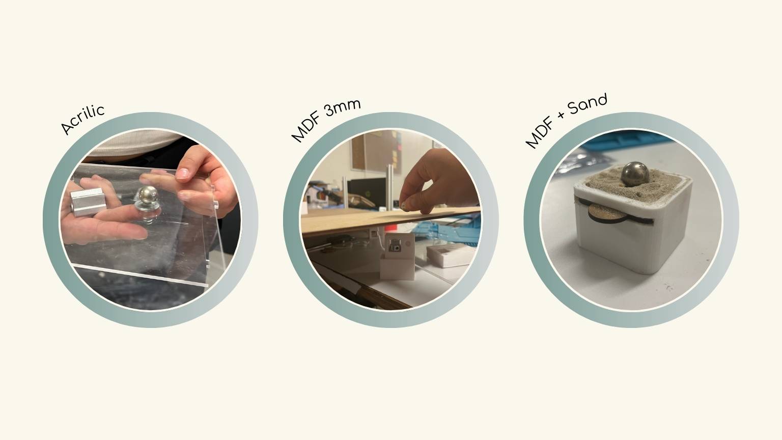
Magnet Test
I made different tests with the magnet and the metal marble that would be used to draw the drawings, the tests that I made were:
- In 5mm acrylic.
- Acrylic of 3mm.
- MDF of 3mm
- MDF of 3mm and sand
Problems and how the team solved them
Organization
Assigning tasks to each team member was a bit of a challenge for me.
I am a person who likes to be organized ahead of time, and even more so by taking the Fab Academy along with my bachelor thesis, so this stressed me out a bit. So, I would have liked to have had more of a breakdown of what we wanted to accomplish—the tasks assigned with attention—instead of looking at it as we went along.
In the end, I think it turned out well because we managed to finish our machine successfully, but that doesn't take away the stress I suffered (nervous laughter).
Redesign
We had to redesign the mechanism parts since the original mechanism consisted of the head moving diagonally. So, we changed to a Cartesian plane movement to be able to perform the programming according to our knowledge as a team.
So, we redesigned the pieces, and there are the new parts:
- Profile base.
- Motor support.
- Toothed belt feed-through.
- Centerpiece for the magnet.
- Side piece for movement A.
- Side piece for movement B.
- MDF Box.
- Lid for side parts.
- Tape A.
- Tape B.
In this case, the movement is like the next diagram:
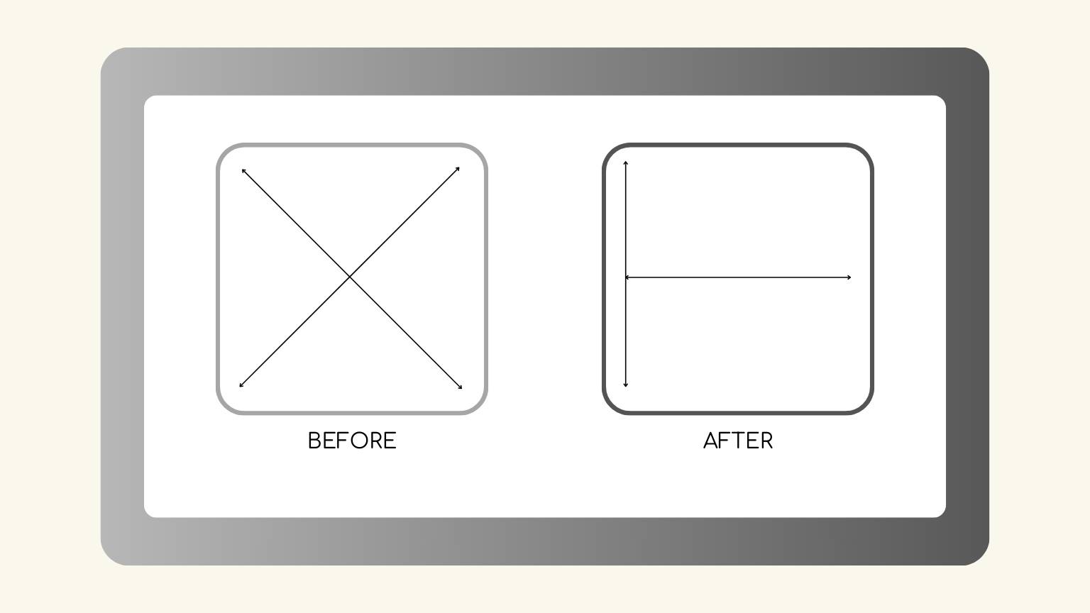
We use a machine coordinate system (MCS) in this case. The MCS is the fixed reference frame of a CNC machine and is defined by the machine origin. The machine origin is typically located at the end of the travel of each axis.
3D Printing
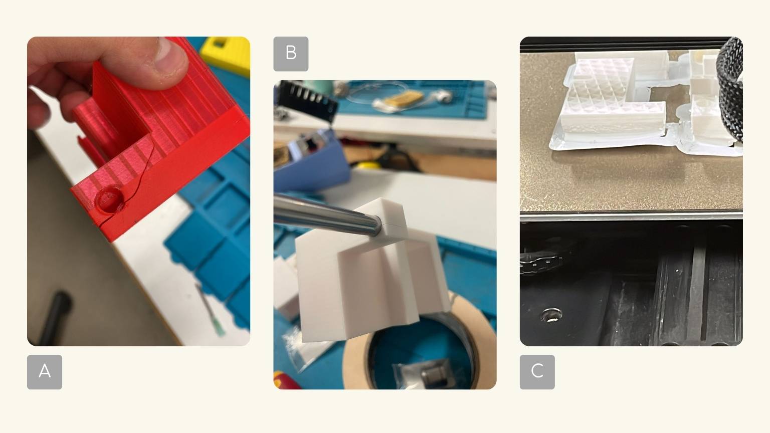
We faced several printing issues primarily stemming from subpar part designs:
(A) Some parts had uneven surfaces near their edges, making it challenging to assemble other components properly. This lack of adequate support resulted in difficulties when applying pressure during assembly.
(B) Additionally, certain parts failed to consider the shrinkage that occurs during cooling. This oversight led to dimensional discrepancies, causing some parts to only fit together under significant pressure.
Other issues were tied to printing parameters, machine calibration issues, and the cleanliness of the printing beds (C).
Improvements...
- Improving the design.
- As the base for the drawings, try a circular shape.
- For the sandbox, we can use acrylic and incorporate Neopixels.
Conclusion
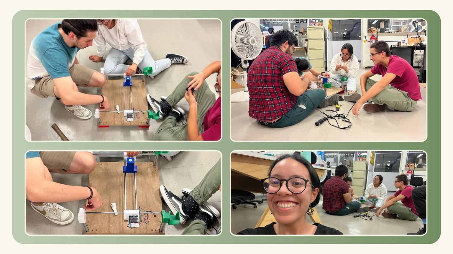
It was truly an intriguing week, filled with unexpected learnings. One of the highlights for me was experiencing the collaborative dynamics within a multidisciplinary team. I found it incredibly enriching to learn from one another and gain diverse perspectives when it came to problem-solving.
On a different note, I never would have imagined that I'd have the opportunity to build a machine...
... but we did it!
Slide