5. 3D Scanning and printing
3D Printing
What should I know before 3D printing?
3D Printing
A computer model can be transformed into an actual, solid, three-dimensional object through the process of 3D printing, which typically involves applying numerous thin layers of a material one after the other. Because 3D printing makes manufacturing more accessible than ever, its popularity has grown rapidly.
Technologies
- Stereolithography (SLA) is like wielding a magical light wand, transforming liquid plastic into exquisite structures. A UV laser methodically hardens liquid resin in a tank, layer by layer, until the required item is formed. Perfect for creating intricate sculptures with clean finishing.
- Selective Laser Sintering (SLS) involves distributing a small layer of powder and then directing a laser to fuse it into a solid piece. It creates products by layering powder together, removing the need for support structures and allowing for complex shapes.
- Fused Deposition Modeling (FDM), like a powerful hot glue gun, FDM warms and extrudes plastic filaments to build up things layer by layer. It's extensively utilized, extremely adaptable, and ideal for prototypes and functioning components.
- Digital Light Process (DLP) is similar to SLA but uses a digital light projector to concurrently illuminate each layer with a single picture. Its speed comes from curing complete layers at once rather than laser-drawing them.
- Multi Jet Fusion (MJF) involves spreading a layer of powder and then coating it with a binding agent triggered by infrared light. This process produces beautifully detailed and durable pieces, making it suitable for both prototypes and completed goods.
- Think of PolyJet as a high-end inkjet printer for 3D printing. It releases microscopic droplets of photopolymer that is quickly cured by UV light. PolyJet allows for complex details and material mixing to achieve varied characteristics and hues in a single print.
- Direct Metal Laser Sintering (DMLS), like the metal-focused variant of SLS, uses metal powder and a laser to create metal components layer by layer. It's ideal for creating high-strength, complicated components and prototypes without the need for molds.
- Electron Beam Melting (EBM) uses an electron beam to fuse metal powders together layer by layer in a high-vacuum environment. It specializes in developing long-lasting, stress-resistant components, which are very valuable in the aerospace and medical industries.
The Printers
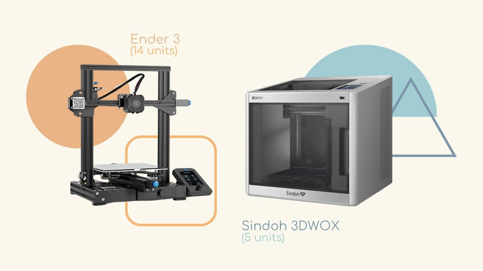
Ender 3 printers are popular in the 3D printing industry due to their cost and dependability, making them ideal for both beginners and professionals. They are adaptable, easy to use, and suitable for a variety of printing jobs.
Sindoh printers are known for their user-friendly design and high-quality prints. The 3DWOX models are especially suitable for educational settings, as they offer enclosed printing areas for safety and consistency in printing.
Design Rules
- Overhang: refers to model components that stretch across an area with no substance beneath them.
- Angle: The printing angle of a feature without support varies depending on the material and printing process. Angles up to 45 degrees are often possible without supports, but this depends on the material and printing method
- Bridging: is about spanning a gap between two portions of a print that lack support below. The success of a bridge is determined on the material's
qualities and the printer's capabilities, with shorter spans being simpler to bridge.
- You don’t use supports.
- Wall Thickness: The minimal wall thickness that can be effectively printed, which affects the object's longevity and structural integrity.
Thin walls may not print properly, but extremely thick walls might waste material and time.
- How big a hole must be to be precise.
- Dimension:are critical, especially for functional components that must work together. Variations in 3D printing might occur as a result of material shrinkage
or printer calibration difficulties.
- Plastic changes size due to cooling.
- Anisotropy:The layer-by-layer manufacturing of 3D printed things allows for varied strengths in different orientations. This must be addressed throughout the design phase, particularly for mechanical parts under stress.
- Infill: The interior of a 3D print is known as infill, and its density may be changed. 0% is hollow, whereas 100% is solid.
- The infill pattern is the structure and form of the material inside a component. Infill patterns, which range from basic lines to more complicated geometric designs, can impact a part's strength, weight, print time, and even flexibility.
- Lines, Zing, Lighing: the fastest. Not good with stress
- The medium speed ones withstand more stress.
- Slow speed ones give more rigidity. More mechanical properties.
- Surface finish: The roughness or smoothness of the print's surface. The surface finish is affected by the printer's resolution, the material, and post-processing processes such as sanding or chemical smoothing.
- Clerance: The clearance between the support structures and the printed portion is crucial. Sufficient clearance ensures that supports can be removed easily without damaging the print. The required clearance varies from 0.2mm to 0.5mm depending on the material and print quality.
To learn more, visit the Week 05 of FabLab Puebla.
What did I do this week?
Designing the object
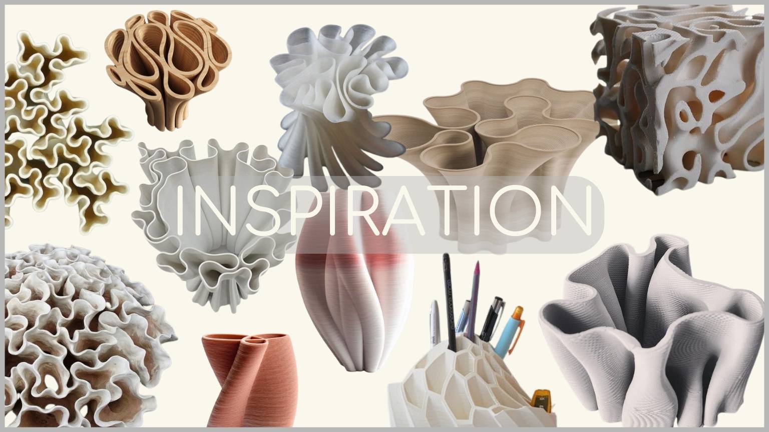
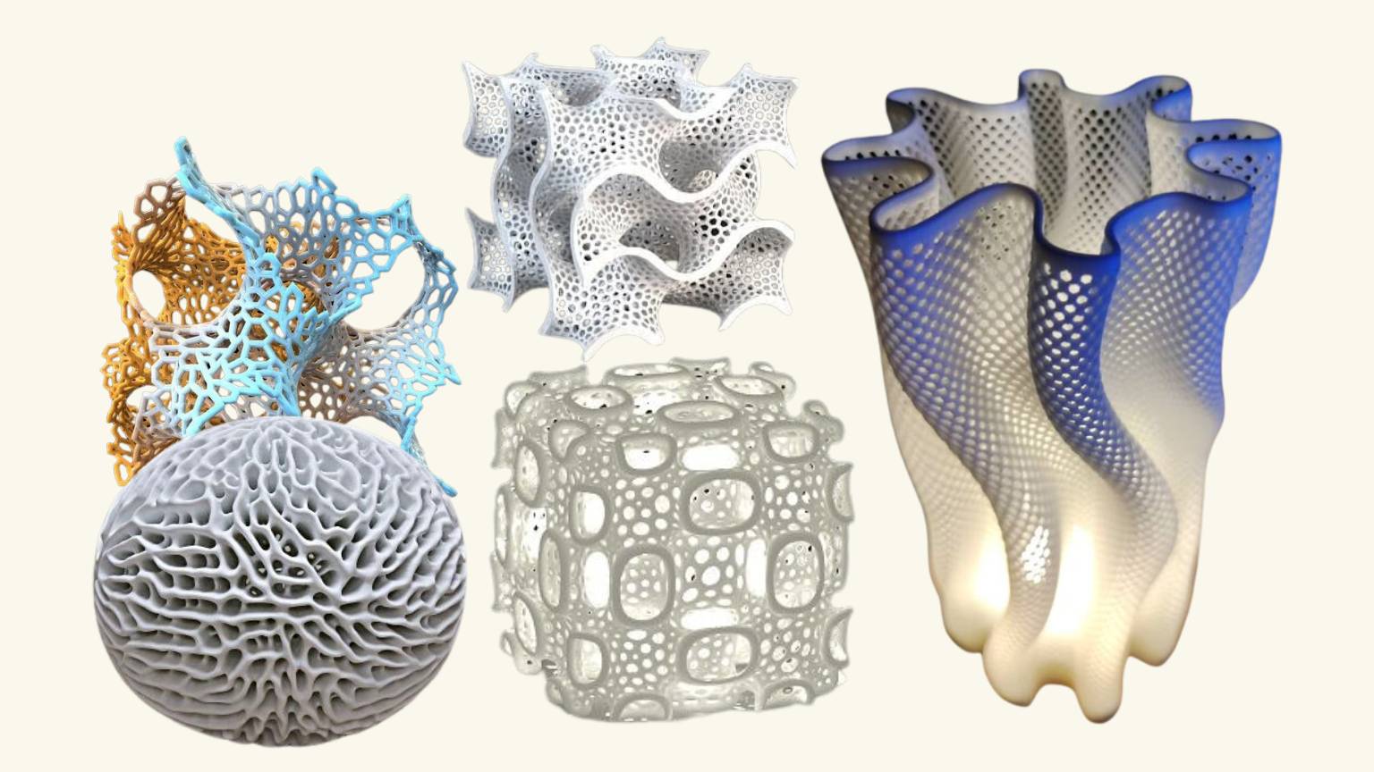
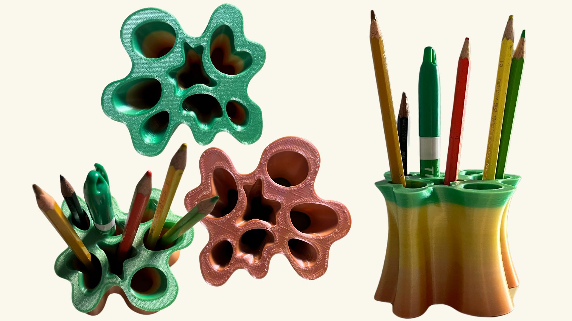
This week, I wanted to experiment with more organic shapes and searched for a suitable object to 3D print. I came across several shapes that played with curves and unevenness, which inspired me to create a pencil holder based on coral shapes. The next images show some of the pieces that inspired me:
Modeling my object
The software: Rhino
To model, I used Rhino 7 because it is the most suitable software for creating organic pieces and I have experience using it.
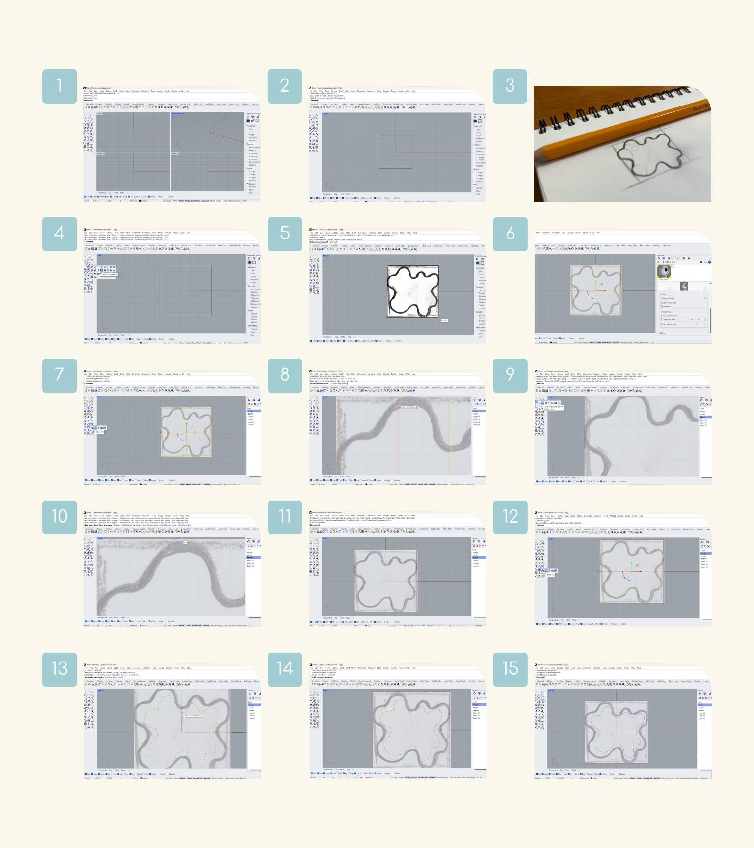
What steps did I follow to design my object?
- I opened the software and created a new project in small object-millimeters.
- On the top view, I made a square to guide the space and dimension that I wanted for my object.
- I drew a sketch of the form in which I visualized my object.
- So, I added the picture of my sketch with the ‘Picture’ command.
- The square helped to limit the size of the image.
- I changed the transparency of the image in the menu of ‘Materiales’.
- This is the proposal to see the traces that I will make next.
- To make sure that the size of the image measurement was correct and to verify that the stroke spanned the frame, I used the ‘Scale 2-D’ command.
- I selected the different reference points to determine the scale of the object.
- Then, I selected the ‘Curve: interpolate points’ command.
- I began to trace my figure using the image I had previously placed as support.
- I finished the sketch.
- After that, I made a copy of the figure and then scaled it to a small size.
- The purpose of this isn’t to create a flat figure but to give it more movement and undulation.
- Note: I tried to use the ‘Offset’ tool, but it didn’t work because it made the curves more geometric and sharp and even added too many control points to the curves.
- I scaled the figure thumbnail as a reference to the center point of the original figure. The shape wasn’t what I expected; I wanted something that kept the same shape but was smaller. So, I modified the points of the curve and moved the necessary points to create the shape I wanted.
- The figure began to take the shape that I wanted.
- I realized the last modifications.
- I remembered to save the document.
- P.S. Don’t forget that!
- I decided to create another copy of the original figure. And I reduced the size a little bit.
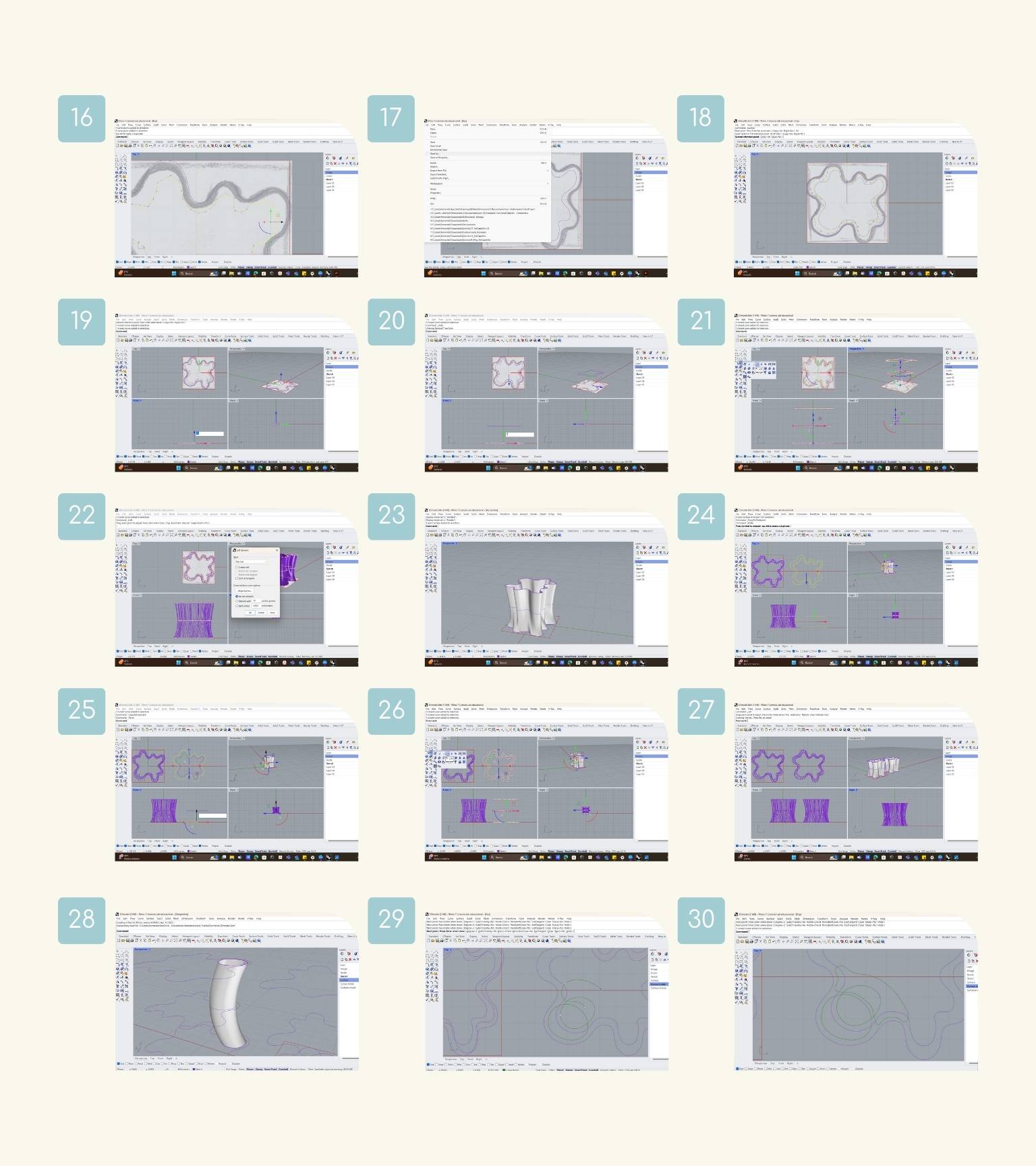
- I moved the shapes according to the z-axis. First, I moved 3.5 mm from the second curve that I created.
- Note: So far, I am realizing that I was working in millimeters, and I should have put the measurements that way (when I made this, I was thinking in cm).
- After, I moved 7 mm from the last curve that I created.
- I used the ‘Loft’ command.
- I only selected the curves in the order in which the surface should pass through them and pressed enter.
- Note: This command fits a surface through selected profile curves that define the surface shape.
- The options box appeared; I kept the normal style and pressed ‘OK’.
- And I have my surface.
- I experimented using only two types of curves: the original curve and the smaller.
- So, I moved the smaller 3.5mm on the z-axis to be the average curve.
- Then, I created a copy of the original to move 7 mm to the upper curve.
- I selected the curves and applied the ‘Loft’ command.
- Now, I have two surfaces.
- At first glance, there wasn’t a major difference between the surfaces. But there was a minimum at the top, as it was a small curve compared to the base curve.
- I decided to keep me with the second surface that I was created to make this another surface.
- So, I started to create the curve with the ‘Curve: interpolate points’ command.
- To make this curve, my guide has the external curve (the bigger one).
- After a lot of changes, the curve looked like in the image.
- I made the second curve, referring to the internal figure and the shape of the previously made curve.
- After moving the curves (the bigger ones at the top and bottom and the smaller ones in the middle), I selected the three curves and applied the ‘Loft’ command to create the surface.
- And this was the result. I felt that the surface wasn’t as continuous, so I decided to eliminate it and make them all more elliptical.
- The internal forms that I made were left like in the image.
- I started to create curved surfaces.
- I visualized the surface containing everything to see if there was any splicing of surfaces. There was a splice with one of the surfaces located in the center.
- I tried to fix the curve with the control points of the curves.
- I made the surface again, but it was still splicing.
- After correcting the points again, I re-created the surface, and there was no longer a joint.
- I continued creating the missing surfaces until I had all of them.
- Next, I hid the surfaces to be able to work only on the outer surface.
- Then I used the ‘Cap’ command to cover the piece.
- This command fills planar holes in objects with planar faces.
- Then, I previewed the internal surfaces again to make an extraction of these in the main piece.
- To do this, I used the ‘Boolean difference’ command, whose function is to trim the shared areas of selected polysurfaces or surfaces with another set of polysurfaces or surfaces.
- And this was the result!
Printing my object
How did I 3d print on a Sindoh print?
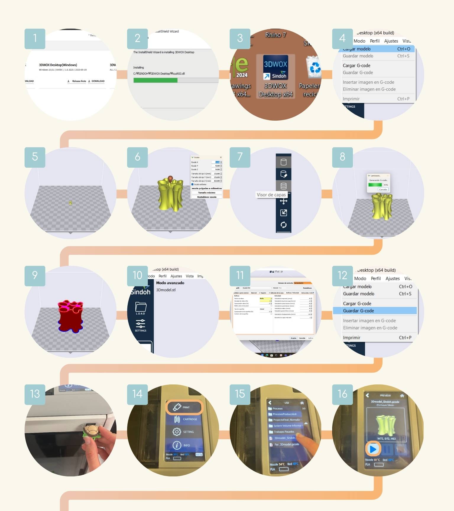
- After printing, I have to download the ‘3DWOX Desktop program’ to configure the file that would print.
- I carried out the relevant steps for the installation.
- Then I opened the program.
- I pressed the file option and clicked on ‘Download Model’ to previsualize the model.
- The model was very small.
- As you may remember, I made my piece in mm, and so it opened like this..
- So, I scaled the model to 9.
- Then, in the side menu, I pressed ‘Layer view’.
- Started loading previews.
- The preview loaded.
- I pressed ’Settings’ to configure some of the printing features.
- I changed the next parameters:
- Layer Height: 0.28
- Wall Thickness: 0.8
- Nozzle temperature: 210
- Bed temperature: 65
- Filling pattern: Malla
- Filling density: 5
- Filler overlar: 15
- Priting Speed: 100
- Then, I downloaded the Gcode file on a USB.
- I put the USB in the printer.
- I pressed the ‘Print’ option.
- This detected the USB, and then I selected the file that I want to print.
- I saw the preview and pressed start (the ‘Play’ option).
- The machines showed a notification. If there is an object on the bed, it will be removed to start the printing process.
- The printer started to adjust the temperature.
- After that, it started printing.
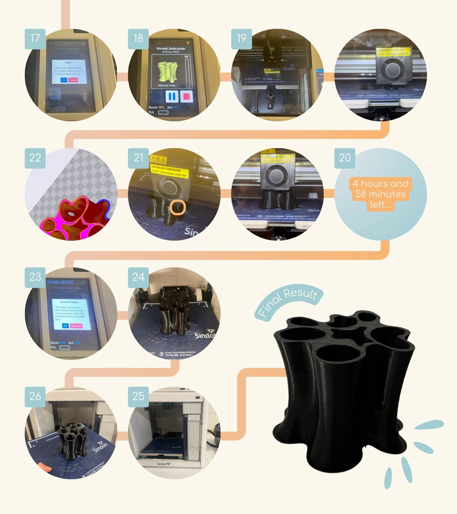
- 4 hours and 58 minutes left...
- During this time, I noticed that there were certain areas where there were small holes.
- I opened the ‘3DWOX Desktop program’ to see if these holes showed up in the preview,
and I noticed that they did.
- Note: Check your preview in depth.
- The printer displayed the prompt for the object to be removed.
- To remove the object, you must wait for the bed to cool down.
- And after detaching the bed and removing the print, press the bed lock button to install the bed.
- I opened the door to see the impression.
- I removed the bed to carefully remove the print and cleaned the bed.
- I reinstalled the bed and removed the USB flash drive.
- And I have my first impression!
| Quality / Exterior Part | Material | Infill / Speed |
|
|
|
|
First print… almost well?
The result of my first impression was almost perfect, but not everything could go right the first time. So, what happened?
Halfway through the printing process, I realized that there were certain areas on the object that had not been completely printed with small holes.
This happened because, playing a little with the unevenness in the model, some parts were very thin, and this prevented the filament from passing through these areas of printing since it was a measure smaller than the thickness of the filament.
But all was not lost, since you can change the measurements of the curves to make the print clean.
Although I have to say that I will use this error as inspiration to make objects like the following ones:
To get the model without the holes was a process of change, trial, and error.
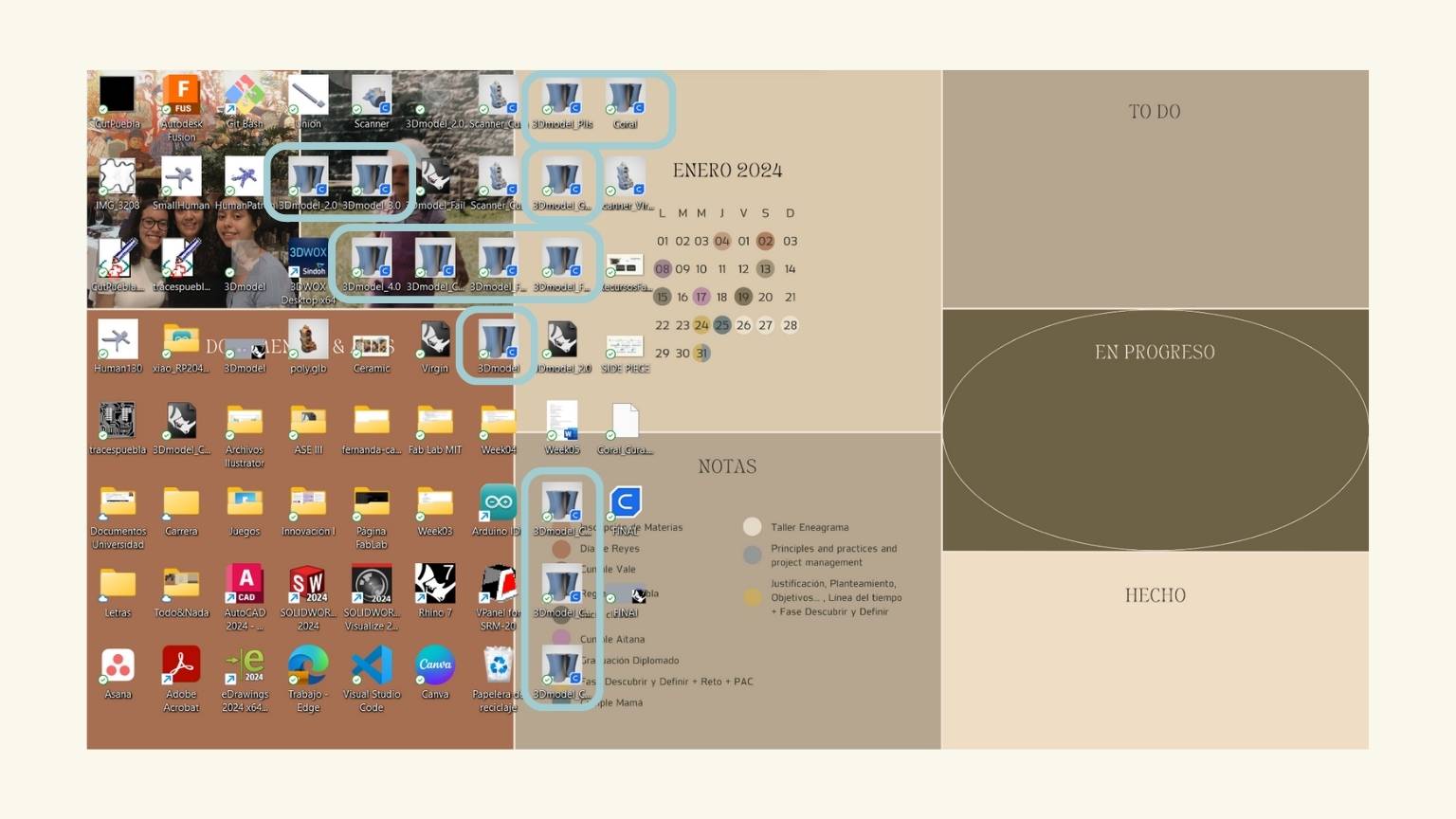
P.S. If you had the pending that I am still in January, I decided to change my calendar in March.
Until finally, a flawless model was achieved.
T I P : My recommendation in this situation is to review the preview of your model and check that everything is correct.
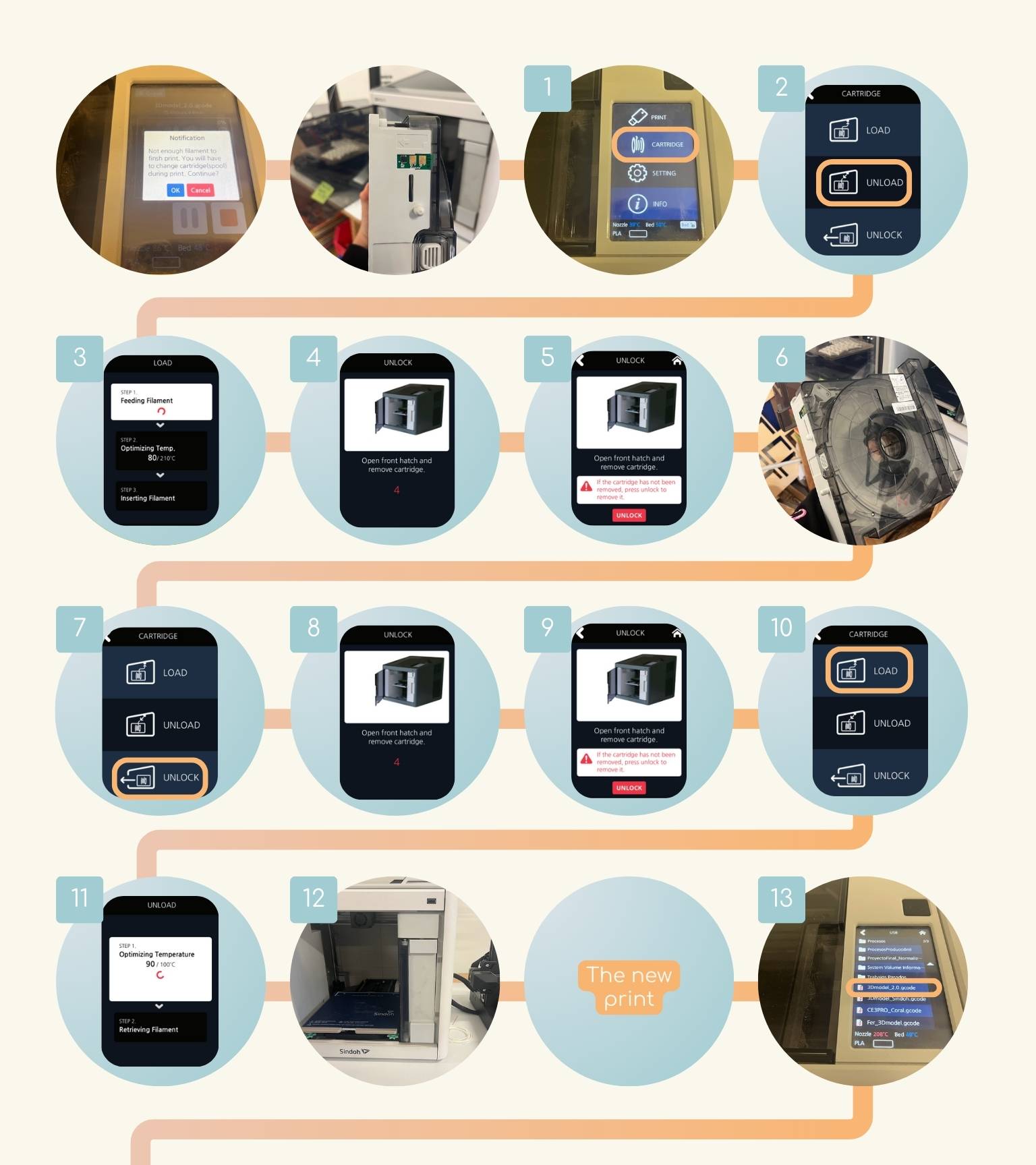
When you place a filament... check what material it is made of!
- Once I had my model ready, I saved it again in the memory to print it, but the machine no longer had filament, so I had to change it.
- Particularly, the Sidoh printer has filament cartridges that have a specific chip according to the material. So, to change the filament, follow the following steps:
- I pressed ‘Cartridge’ in the home menu.
- Then, I selected ‘Unload’ to remove the filament.
- The cartridge unloading was performed automatically in three steps: (1) Feeding Filament, (2) Optimizing Filament and (3) Insertion Filaments.
- To remove filament, the nozzle is heated up to the specified temperature and the filament unloading starts.
- After the filament has been removed, the screen will automatically turn to the ‘Unlock’ screen to remove the cartridge.
- So, for 10 seconds, the ‘Lock’ state was deactivated, and I was able to detach the cartridge from the printer.
- Note: If the cartridge can’t be pulled out even after “unlock”, gently push it forward and then try to pull it out again.
- Then, after 10 seconds, the printer will automatically change to the ‘Lock’ state, and ‘Unlock’ will appear.
- I removed the cartridge.
- Now, to load the new cartridge in the ‘Cartridge’ menu, I went to the ‘Unlock’ option.
- I pressed the option, and I had 10 seconds to insert the new cartridge.
- And after the print was locked.
- To load the filament, I selected ‘Load’ to activate cartridge load.
- The loading of the cartridge was performed automatically. The filament reached the nozzle and was heated to the specified temperature.
- Then, the filament was inserted into the heated nozzle. This happened when two steps were taken: (1) Optimizing Temperature and (2) Retrieving Filament.
- And once the process was completed, the display automatically returned to the ‘Home’ screen.
- The filament was loaded!
- I inserted my USB into the printer and searched for the file.
- The file was opened, and I pressed the ‘Play’ button to start the impression.
- The impression started, and I detected that the material of the filament was different, but I decided to continue the impression to see what happened.
- The impression continued well.
- I detected that the filament in some layers was separated, and that the impression wasn’t continuous. So, I paused the impression to see these errors.
- I decided to cancel the impression and try another.
- After, I checked the filament that was loaded into the machine. To this end, I followed steps 1 to 6.
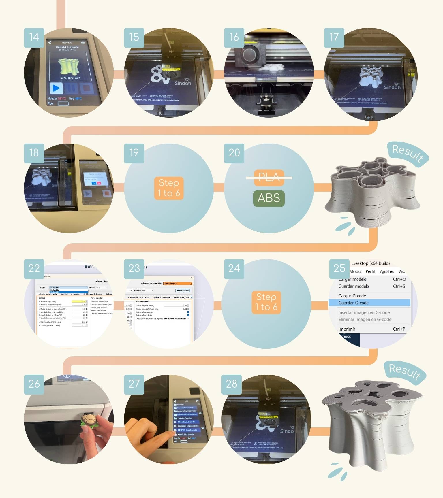
- And I saw that the material of the filament wasn’t PLA but ABS.
- The result of the failure impression.
- The printing parameters were those of PLA, so I changed them to those of ABS.
- I set the parameters to the ABS defaults.
- Then, I tried again to print with the error correction.
- I downloaded the new file on the USB.
- I inserted the USB into the printer.
- I selected the file.
- And the impression started.
Now, I made a new print with the corrections I made to the previous model.
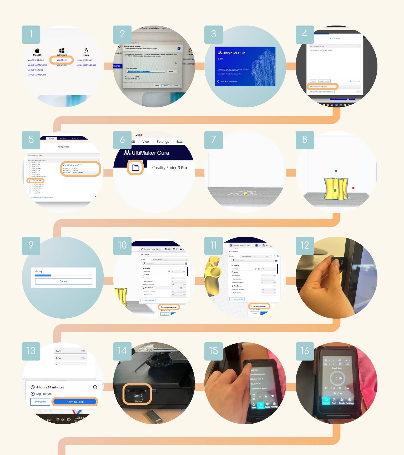
How did I 3D print on an Ender print?
There are really the same steps; the only thing that changes is the program interface.
- First, I downloaded ‘Ultimaker Cura’
- I carried out the relevant steps for the installation.
- Then I opened the program.
- As part of the first steps, the program asked me to set the type of printer that I would be using.
- I searched the printer in the ‘Add a non-networked printer’ section and selected the ‘Creality Ender-3 Pro.
- Then, I opened the file that I wanted to print.
- The model was very small.
- As you may remember, I made my piece in mm, and so it opened like this.
- So, I scaled the model.
- I pressed the ‘Slice’ button to see how long it would take to print.
- With the default settings, printing would take 10 hours and 13 minutes.
- So, I changed the parameters:
- Wall Thickness: 0.8
- Wall Line Count: 2
- Infill Density: 5.0
- Infill Pattern: Zig Zag
- Printing Temperature: 210.0
- Build Plate Temperature: 65.0
- Once the model was revised, I placed the printer's SCD card on the computer to save the print file.
- I saved the model on the disk.
- After that, I introduced the card to the printer.
- I searched for my file.
- I started to print.
- The temperature parameters of the nozzle and the bed started to change to start printing once they reached the indicated parameters.
- The printing started!
- The printing started very well and didn’t seem to have any failures.
- The print continued well, and the first color change could already be seen.
- The printing was 100% complete.
- This was the result.
- I removed the piece from the print bed.
- To remove the filament, I opened the ‘Ready’ menu and changed the ‘Out’ option for the filament to heat up to remove the filament.
- This gear began to rotate counterclockwise, which meant that the filament was already being ejected.
- I removed the filament from the nozzle.
- I turned off the print.
- Finally, I removed the excess print layer.
| Quality | Walls | Top/Bottom | Infill | Material | Speed |
| Layer Height: 0.28 |
|
Stay |
|
|
Print Speed: 100 mm/s |
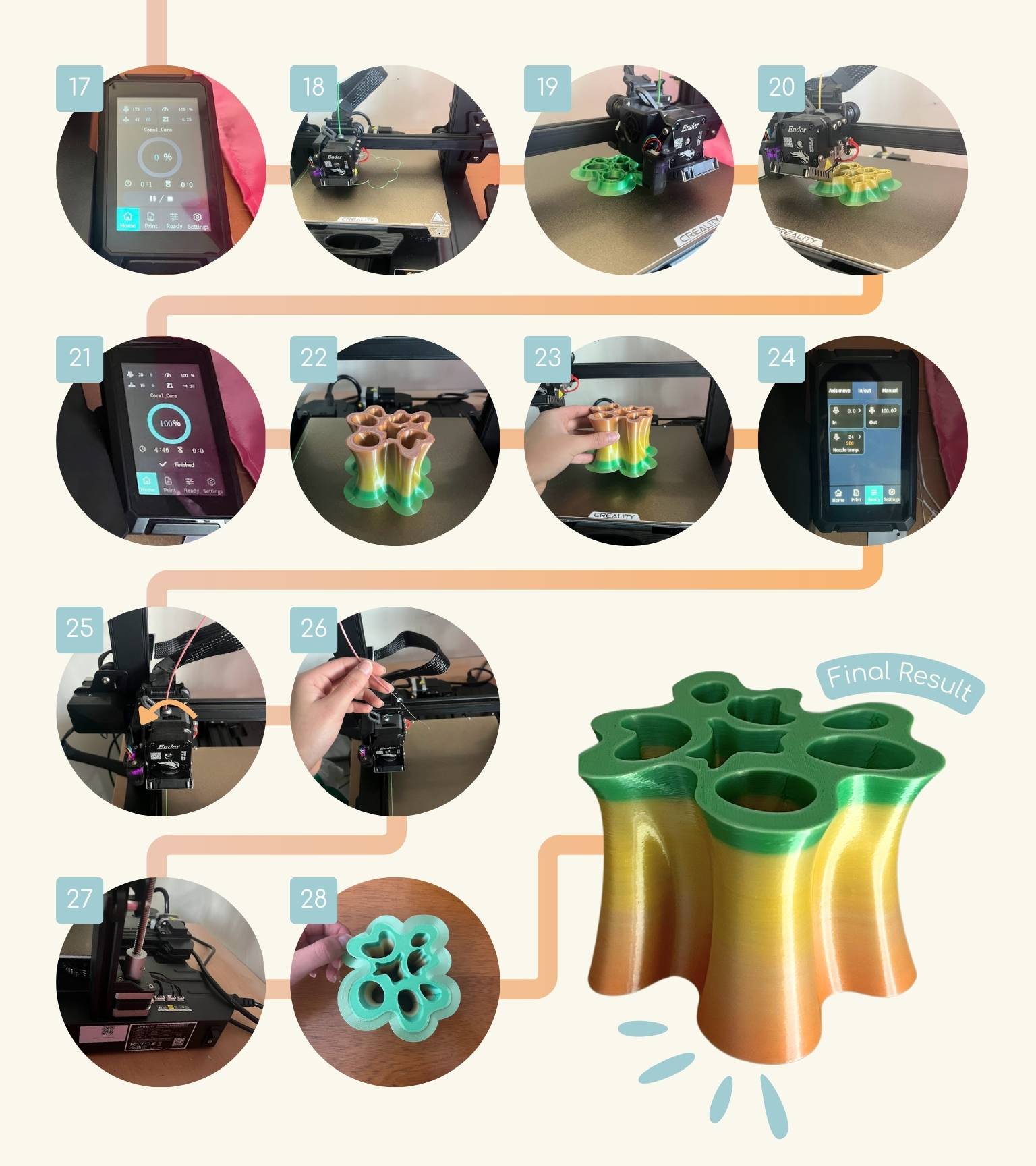
Final Result
3D Scanning
What should I know before scanning?
3D scanning is a technique for capturing the actual shape of an object and converting it into a 3D digital representation. The procedure entails gathering data from the object's surface. To measure and capture these features, 3D scanners employ a variety of techniques, including lasers, structured light, photogrammetry, and sophisticated depth and radiation-based artificial intelligence.
As a result, a format converter is required to transform this data into a format appropriate for 3D printing.
Many 3D scanning tools produce files that are unsuitable for direct printing. These files are frequently based on approaches such as point clouds or surface representations, which do not support mesh-based processing. Mesh-based manipulation is necessary for 3D printing.
Polycam
Polycam is a great 3D capture software for iPhone and iPad. It enables users to create high-quality 3D models from images, scan locations quickly using the LiDAR sensor, and take complete 360 photos with ease. The software also allows for easy editing of 3D captures on the device and exporting them in over a dozen file formats. Polycam Web enables users to share their captures with friends and the Polycam community, while Poly World lets them browse captures from all over the world.
My 3D Scanner
To make this, I decided to scan the clay of a virgin so that it could be cut off. So, how did I scan it?
Scanning
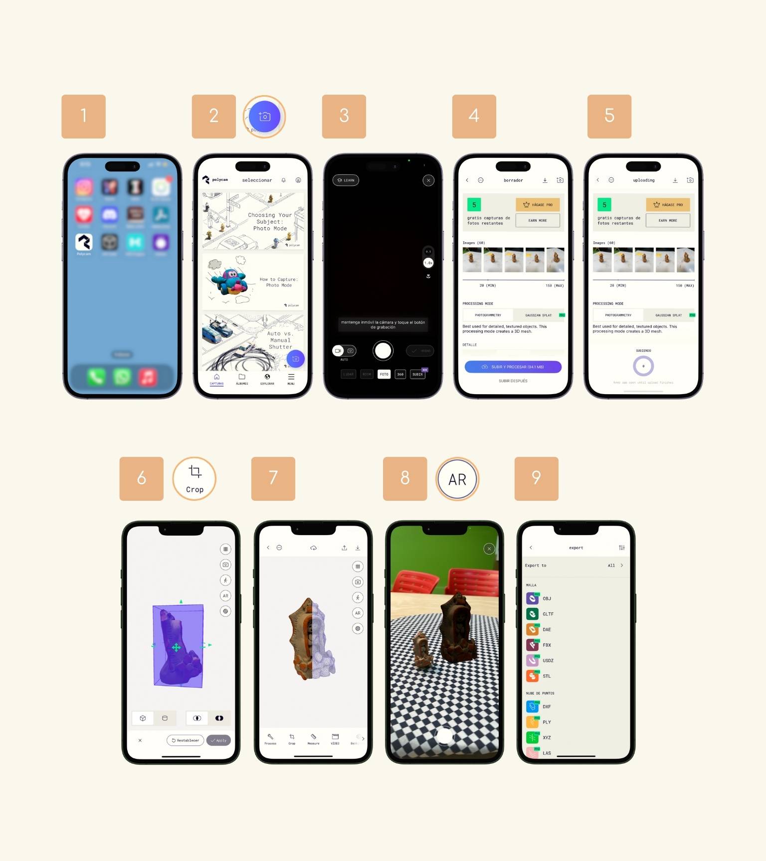
- First, I downloaded the app ‘Polycam’.
- I opened and pressed the ‘Camera’ icon to start the scanning.
- To start scanning, I pressed the middle button and started taking several pictures of my object from different perspectives.
- When I finished, the whole sequence of pictures I had taken appeared, and after reviewing them, I pressed the button ‘Upload and process’.
- It started to upload and took approximately 8 minutes to process completely.
- The model was opened, and I used the ‘Crop’ tool to eliminate some parts of the scanner that don’t belong to the object.
- I have the model!
- Then, I preview the model with the ‘AR’ option to compare it with the real object.
- Finally, I downloaded the object to print it.
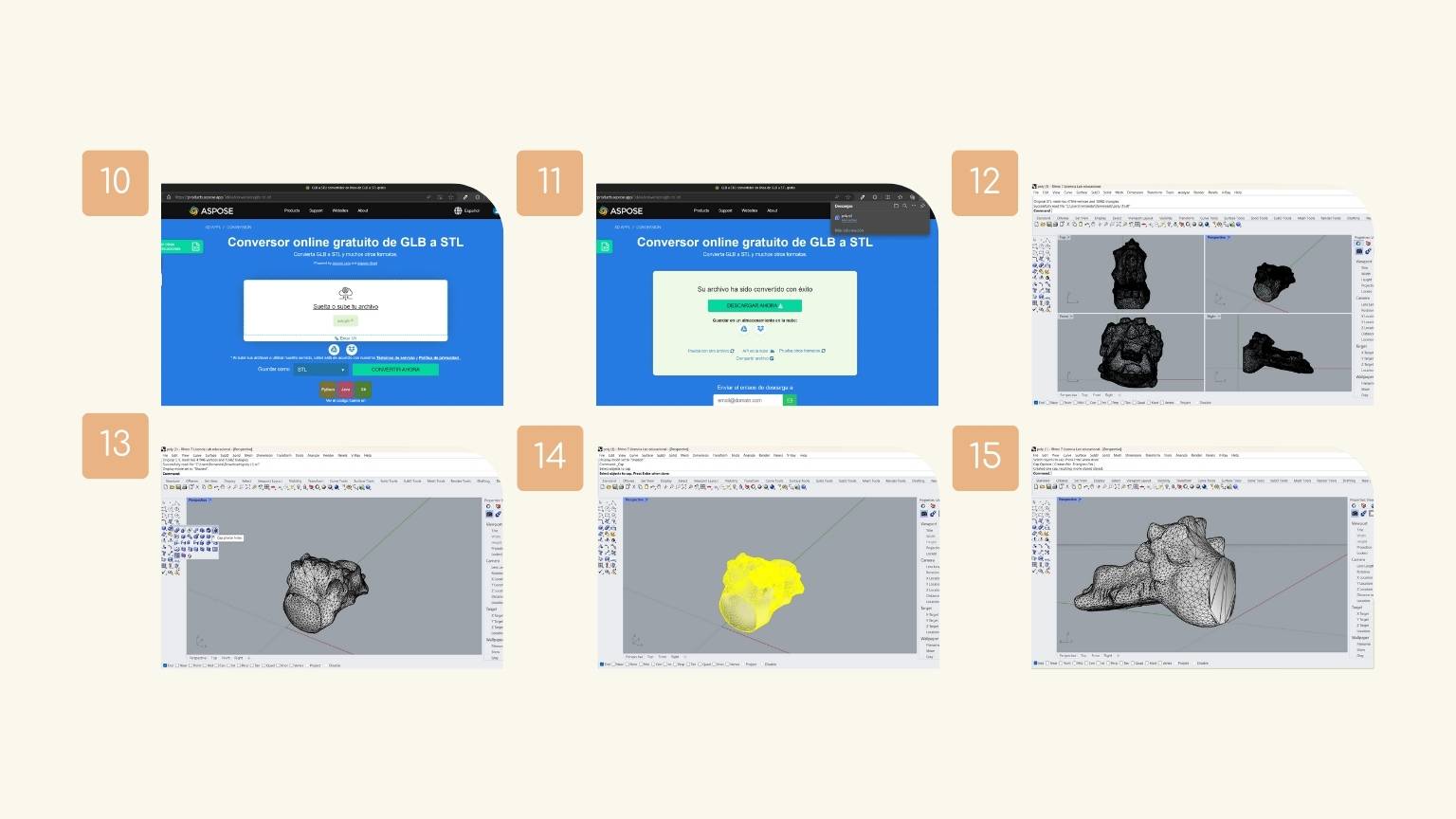
- I could only download it as ‘gltf’, so I looked for a page to convert it to ‘gtl’.
- I uploaded my file, converted it, and downloaded it.
- I opened the file in Rhino to cover the piece.
- I used the ‘Cap planer holes’ command to cover.
- I selected the object to indicate the object to which the command is to be applied.
- The object was covered!
Converting the file
Printing the scanner
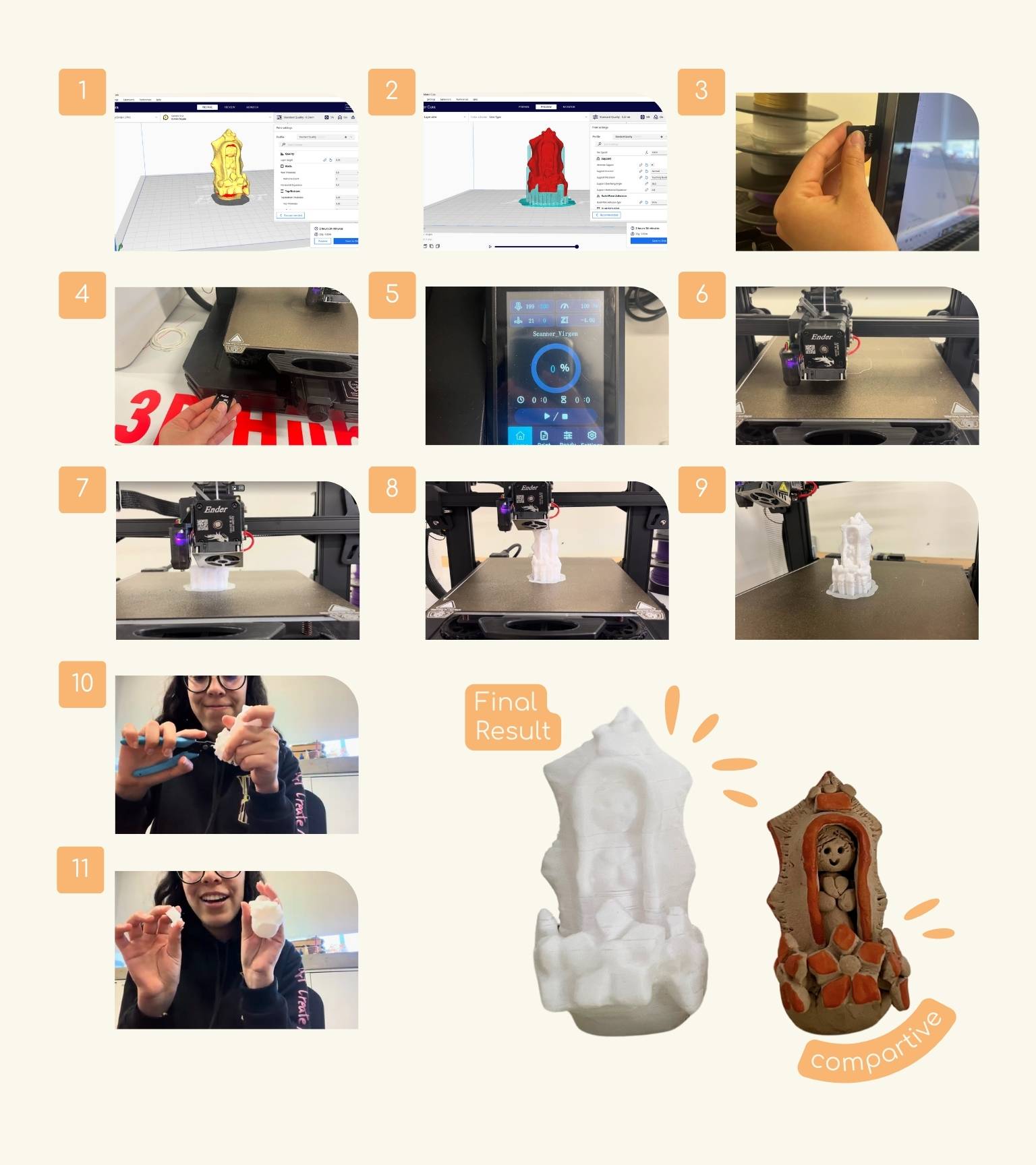
- I opened the model in ‘Ultimaker Cura’.
- I adjusted the settings and applied supports to the piece.
- Then, place the printer's SCD card on the computer to save the print file.
- After saving the file and removing the card from the computer, I introduced the card to the printer.
- I searched and opened my file.
- The printer started printing.
- Printing started when the nozzle and bed temperature parameters changed, reaching the indicated parameters.
- The printing continued well.
- The printing was almost finished.
- I have my scanner printed!
- With the help of tweezers, I removed the supports.
- Finally, I removed all the supports.
Conclusion
This week involved a lot of trial and error, which helped me better understand how a 3D printer works. Understanding design is also crucial because not all ideas can be realized with a certain production method. Therefore, this week was important for learning how a product can be made with a certain method and why it may not be possible with another.
In summary, it is crucial to comprehend the design rules and conduct thorough testing. It is worth noting that mistakes are inevitable, but they often provide valuable learning opportunities.