
12. Molding and Casting
I this week's assignment I was able to design and fab a simple LED control system for a RaspberryPI-4 board.
Before this week's proyect I had never got into working with casts and molds, but it was certainly interesting, and it opened a world of opportunities.
As I had no previous experience I needed to do something not too ambitious yet interesting enough to be worthy for my week's proyect. I was thinking about adding some braking lights to the electric scooter I want to make as a final proyect, and then curiosity struck my mind, I wanted to know if it was possible to design and fab some fresnel lenses like the ones used in automovile headlights and lighthouses. If I make a mold of the lens and pour some clear resin on it, maybe it could work.
The original plan was to use the Roland Monofab mini mill to machine a block of wax, but to my surprise and dissapointment there were no more left on my FABLAB by the time I went to look for them. I opted then to try and use a conventional FDM 3D printer to try and create the mold this of course posed the challenge of obtaining a smooth surface finish right off the bat, as the layers of the 3D printed model would be clearly visible. To solve this I intended to either treat the mold's roughness, or probably easier to do, sand and polish the finished resin piece afterwards.
Designing some lenses:
I am no expert in optics, but I can surely do some research to find ways of calculating fresnel lenses. After some time of looking, and with some help of ChatGPT-4, I was able to calculate a lens that satisfied what I was looking for.
The process I followed to do so is shown next:
Procedures:
I wanted to design a set of fresnel lenses for the brake lights of my electric scooter, and for such purpose I wanted the lights to be clearly visible from far away and as well from the sides. I contemplated then a design with magnification in mind.
Fresnel lenses are basically a transformation of a full concave lens into a much smaller discrete prism array that tries to mimic the behaviour of the original (left image). The prisms redirect light onto the same angles as the full concave lens but with a catch: The more prisms the Fresnel lens has, the more faithful to the original behaviour the lens will be; of course, making things smaller and smaller only makes them more difficult to manufacture. So, to make this possible we have to compromise some optic quality for the sake of manufacturability, which for my application, shouldn't be much of a problem.
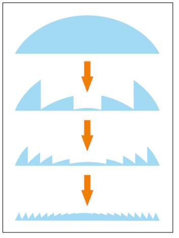
Images from A. Davis and F. Kühnlenz. (Reference at the end)
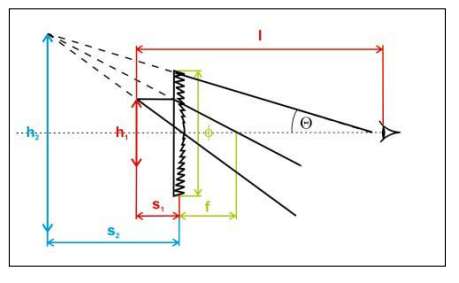
Now, fresnel lenses are designed according to the characteristics shown in the image below:
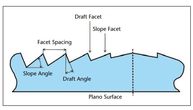
Image also from A. Davis and F. Kühnlenz.
For the sake of simplicity I will only be taking into account the facet spacing and the slope angle, draft angle will be left at 90 degrees (completely vertical) because 3D printing that way is easier.
Also, as said earlier, the Facet Spacing is usually defined by a factor of manufacturability, we can opt for bigger spacings translating in ease of manufacturing, at the expense of optical performance. As I will be doing the mold on a FDM 3D printer, I chose a lower groove count in order to make the facet spacing bigger and easier to manufacture. To do my CAD design I devised a little calculator that takes in the diameter of the desired lens, the desired groove count, and the distance of the light source to the lens; this last input is important as it helps define the angle each facet needs to proyect light as a curved surface.
The calculator uses trigonometry to estimate the draft angle for each groove relative to the light source's distance and its distance to the center of the lens. I programmed it originally using python, but then asked ChatGPT-4 to translate it into Javascript so I could place it in this page for everyone to use. It's definitely not optically accurate nor useful for professional operations, but for my intentions (and maybe for yours too) it does the trick.
Awful Fresnel Lens Calculator
Results:
| Groove # | Slope Angle (degrees) |
|---|
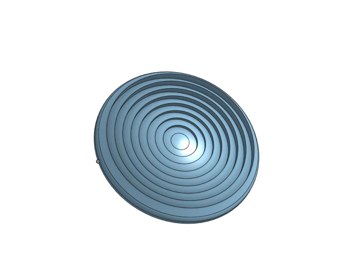
Now that we have the draft angle and spacing values, we can head out to our favorite CAD software, in my case OnShape, and create a parametric design using those characteristics:
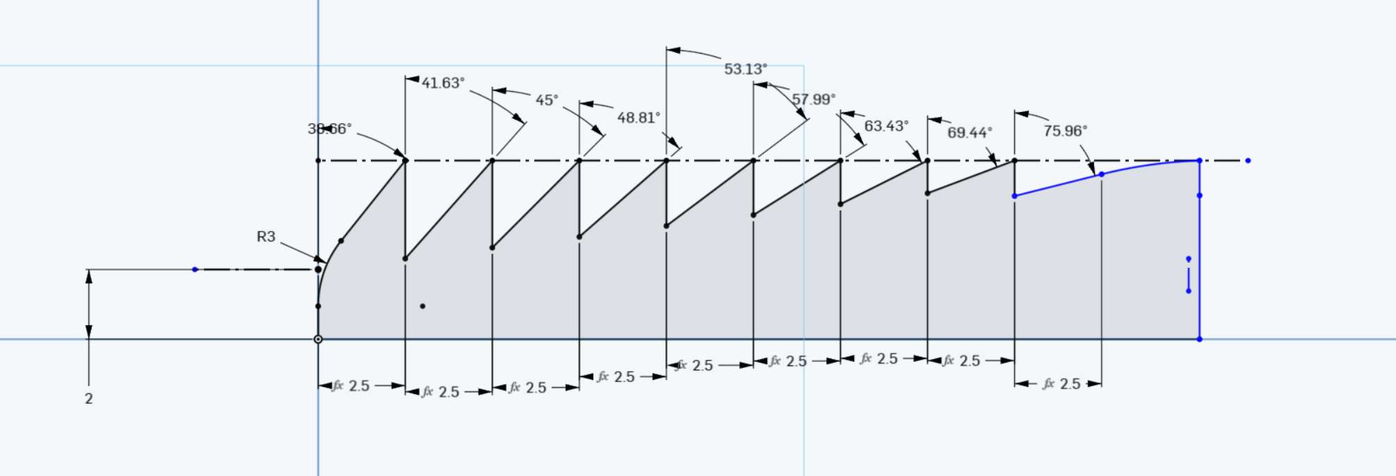
I used variables to make the parameters such as the groove count and facet spacing easily modifiable. The final sketch was then converted into the final 3D model using the "Revolute" tool:
3D Printing the mould:
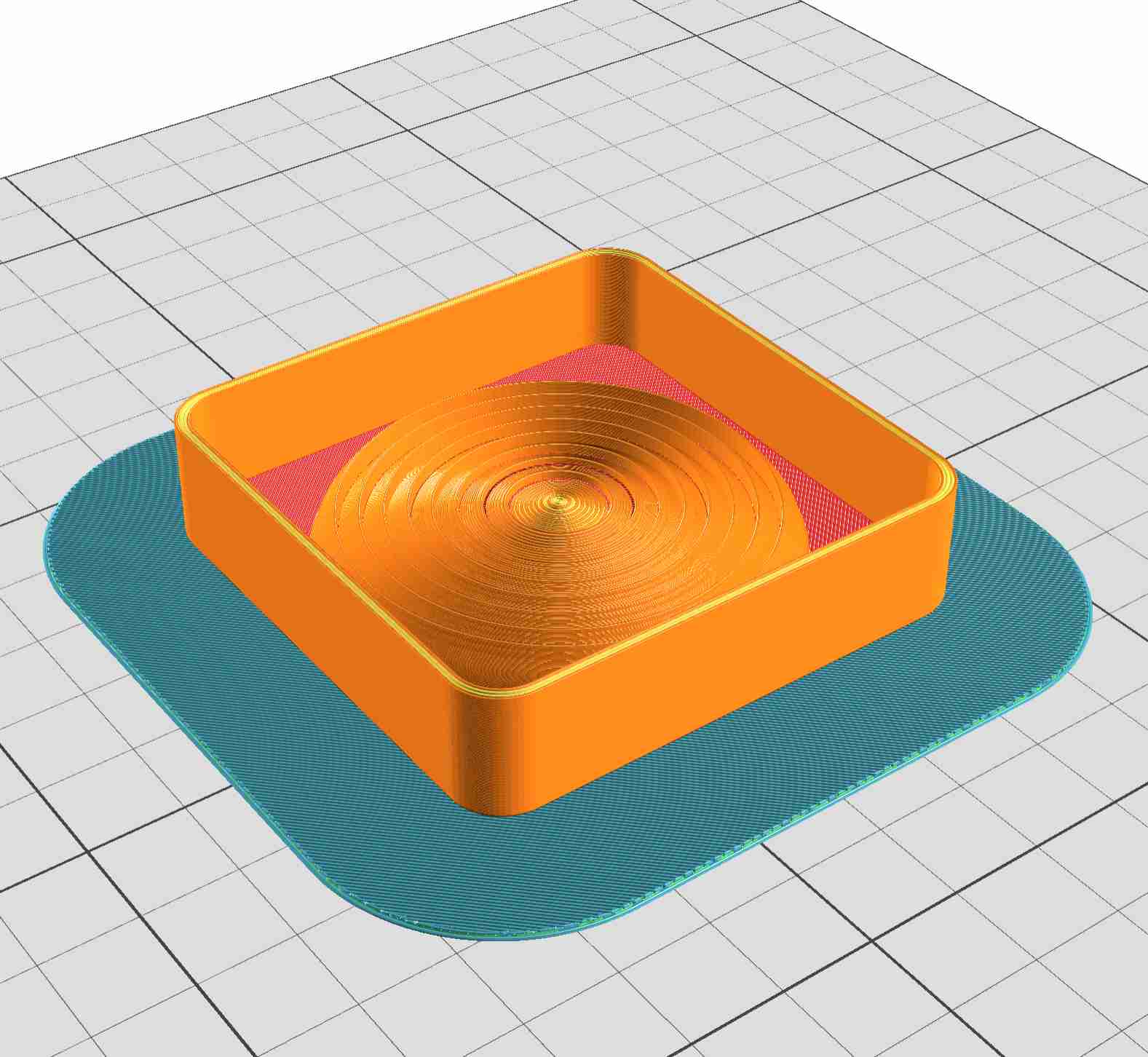
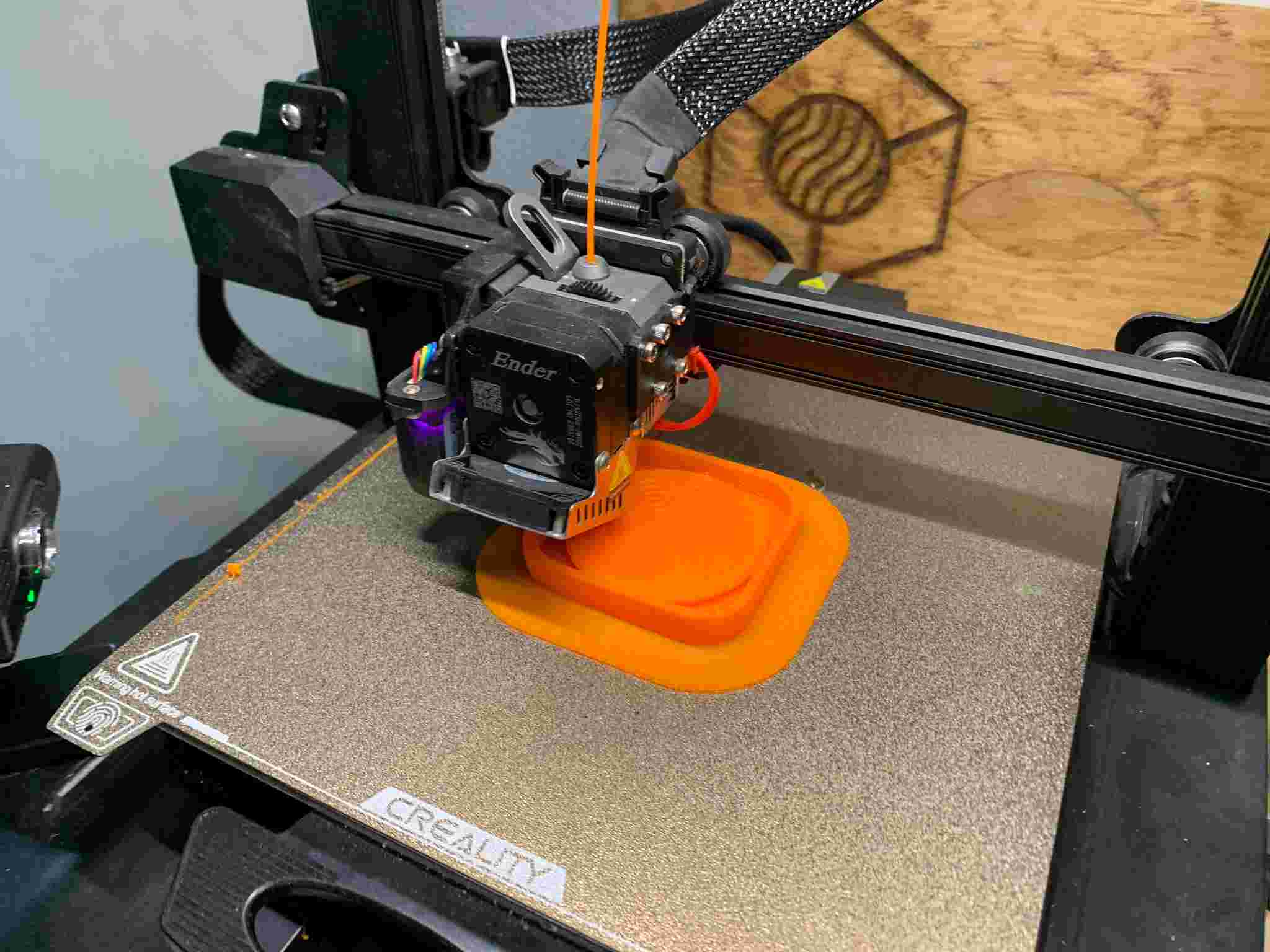
I built a wall around the lens' model, and exported everything into STL and placed it into CURA, where I used the finest parameters my 3D printer allowed in order to obtain a very detailed model of the fresnel lens. I opted then for a 0.1mm layer height at a slow but steady 40mm/s.

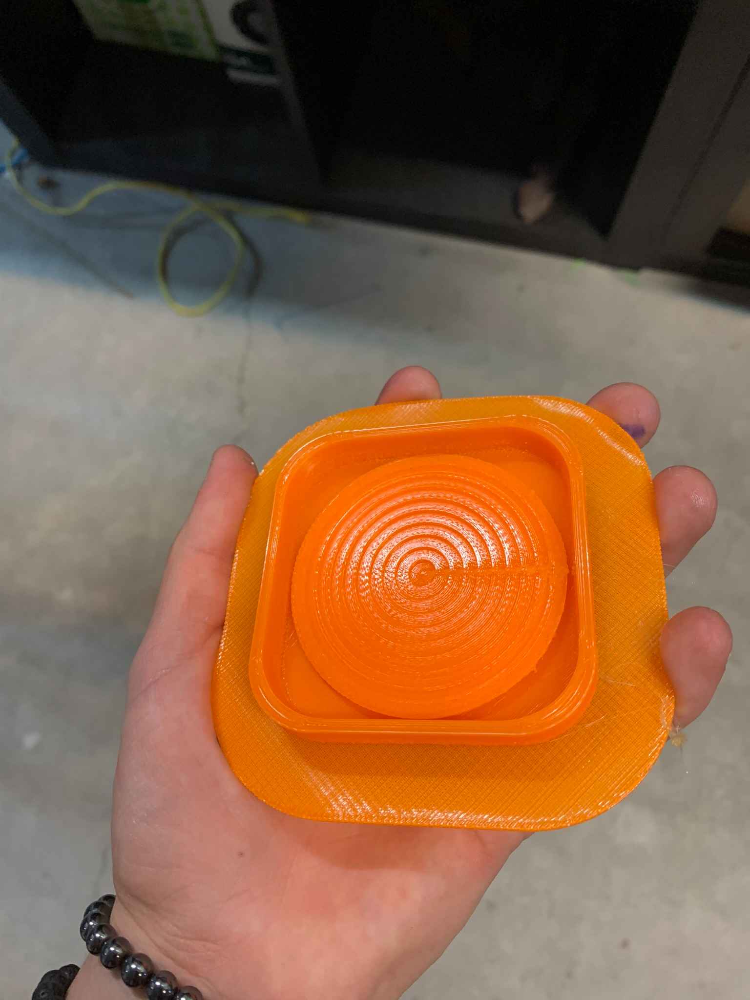
After 2 hours and a half of printing, I finally got my piece ready, which I then sanded a bit in order to remove as much of the FDM texture as possible:
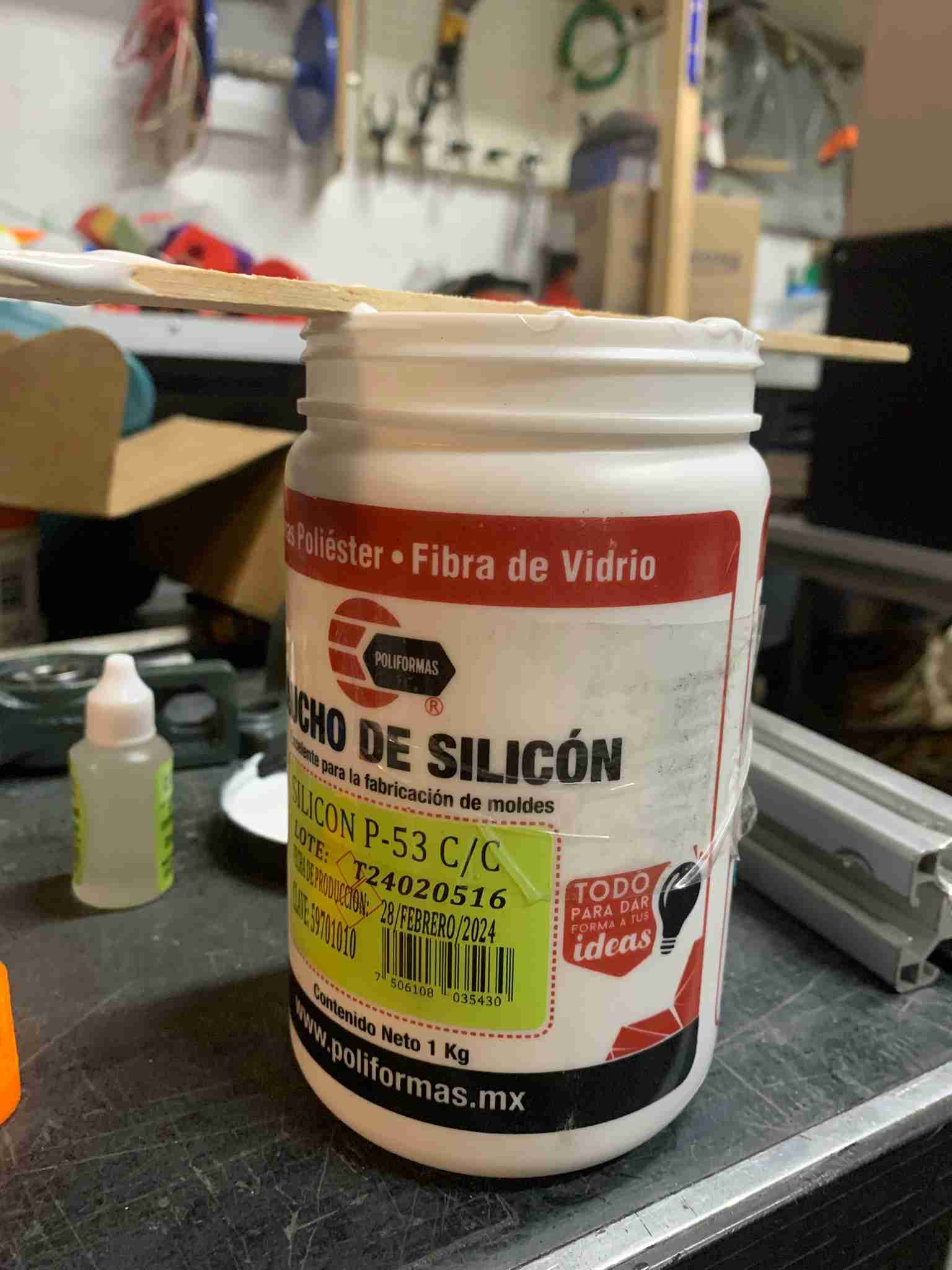
Making a Silicon Mould:
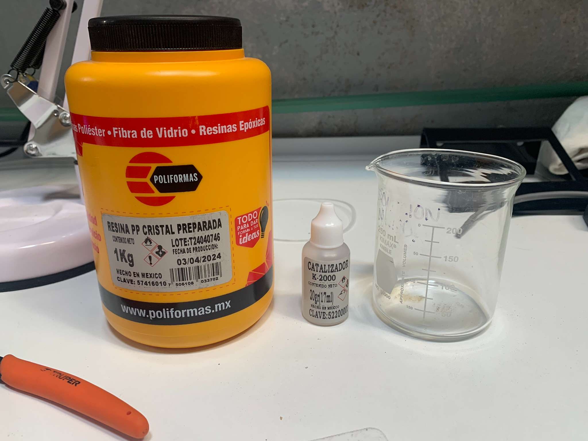
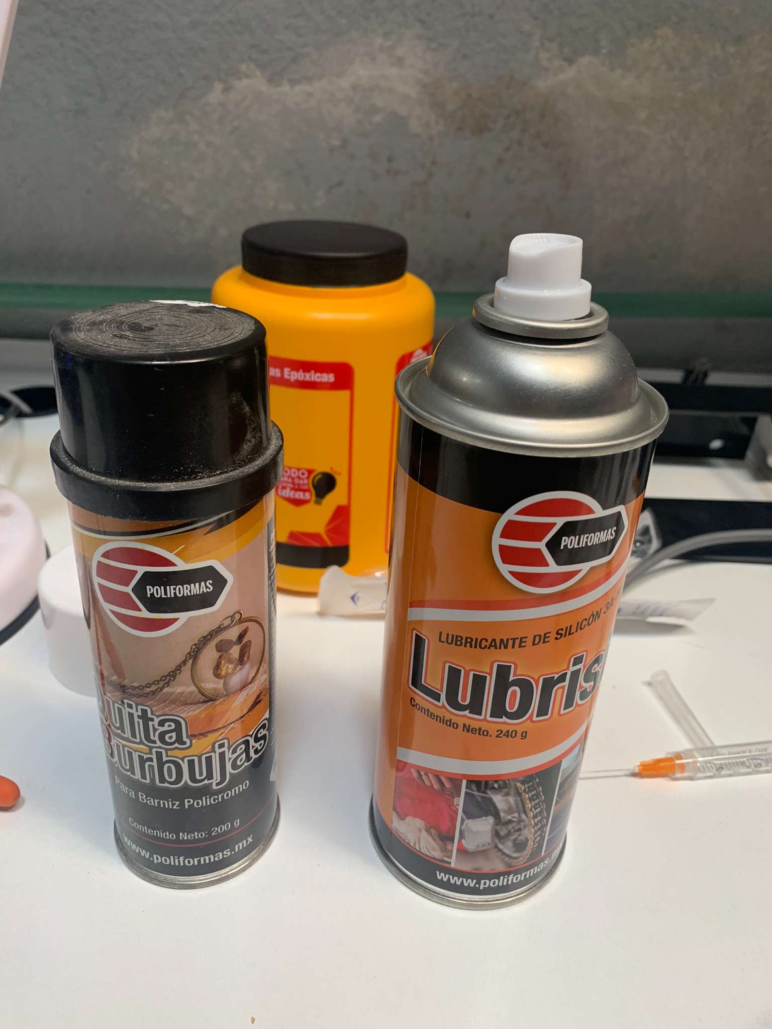
For the silicon mould I used a local manufacturer's silicon compound designed for this purpose. In order for the silicon to cure properly, the manufacturer recommends mixing it with their catalyzer in a 2 to 3% silicon to catalyzer ratio, so I placed a 100mL of silicon in a measuring cup and using a syringe carefully added 3mL of catalyzer. I mixed everything together thourougly after that.
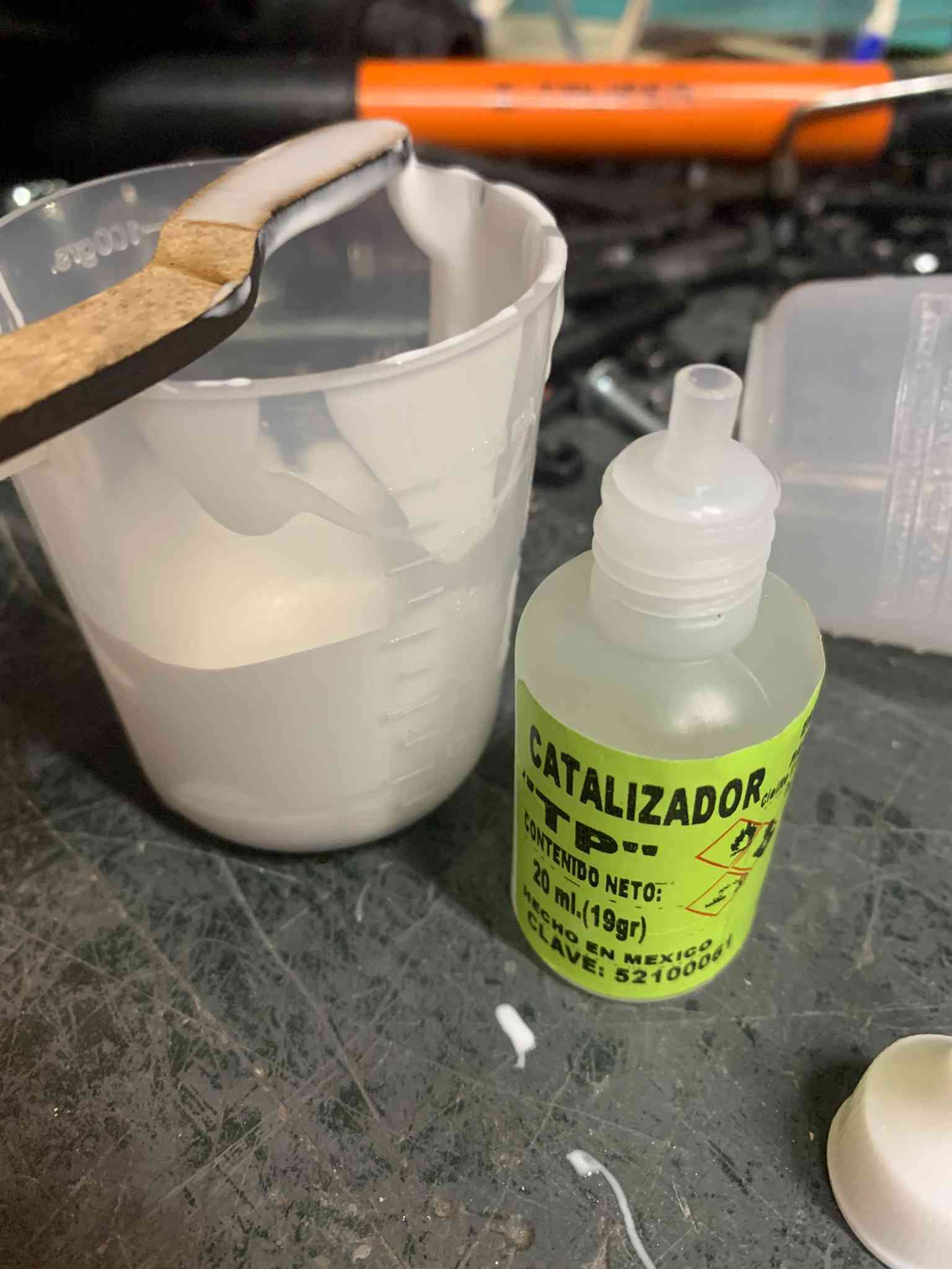
The silicon rapidly started getting thicker, so I poured it carefully onto the 3D printed mould, hit it a few times to get rid of air bubbles, and hoped for the best. The silicon fully cured in a few hours but to my sad surprise, the silicon didnt get into all the parts of the mould and was also filled with air bubbles, resulting in a piece that looked horrible and wouldn't work. Not even the walls of the mould were complete.
I contacted the manufacturer (Poliformas Plásticas) for some info, and they recommended I added some of their silicon dilutant into the mix to make the silicon more fluid and easier to work with. It made a lot of sense, so the next day I went to the store and purchased the product. According to the instructions, I could add up to 10% of the total silicon volume in dilutant, so I went for it.
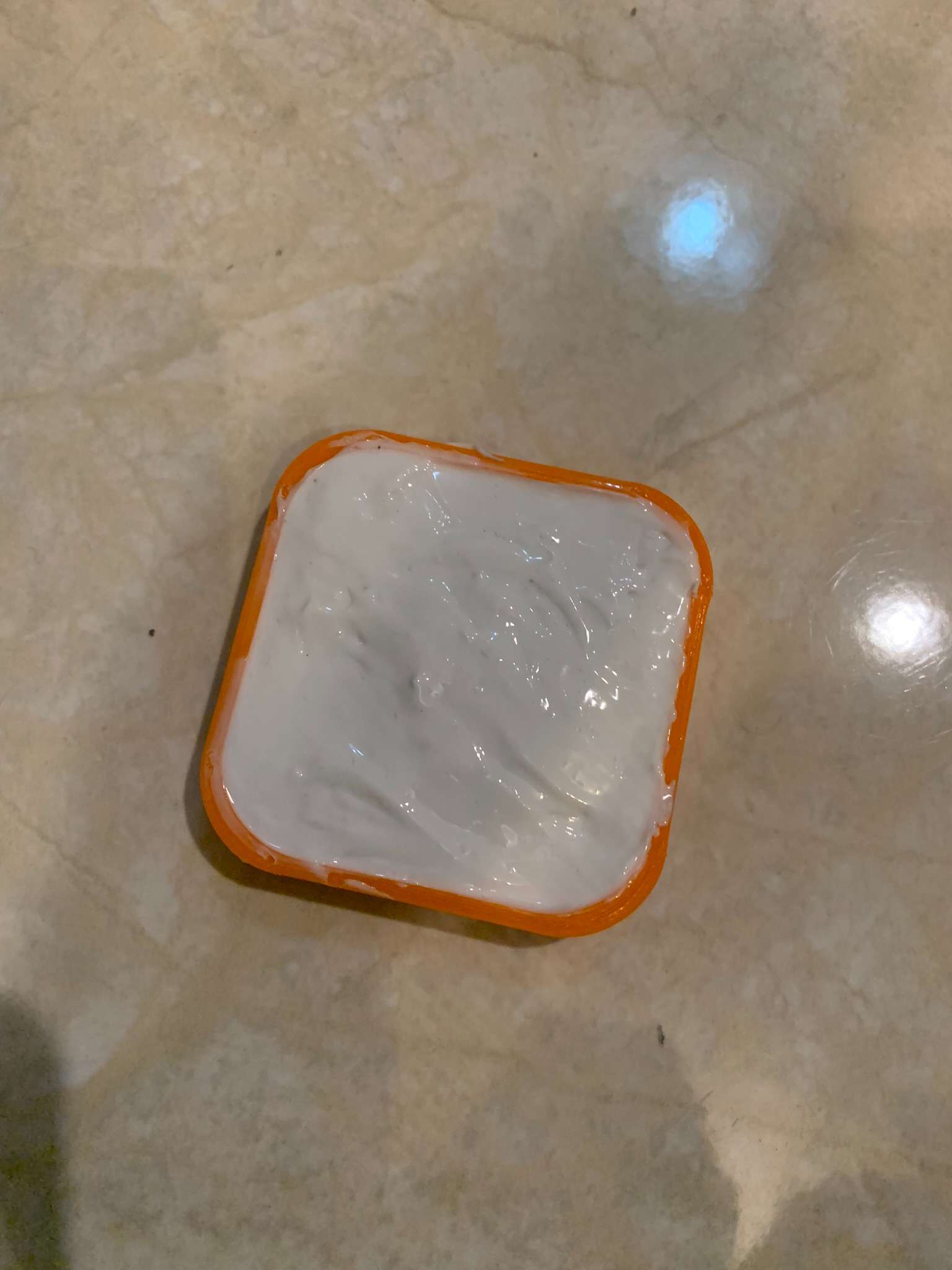
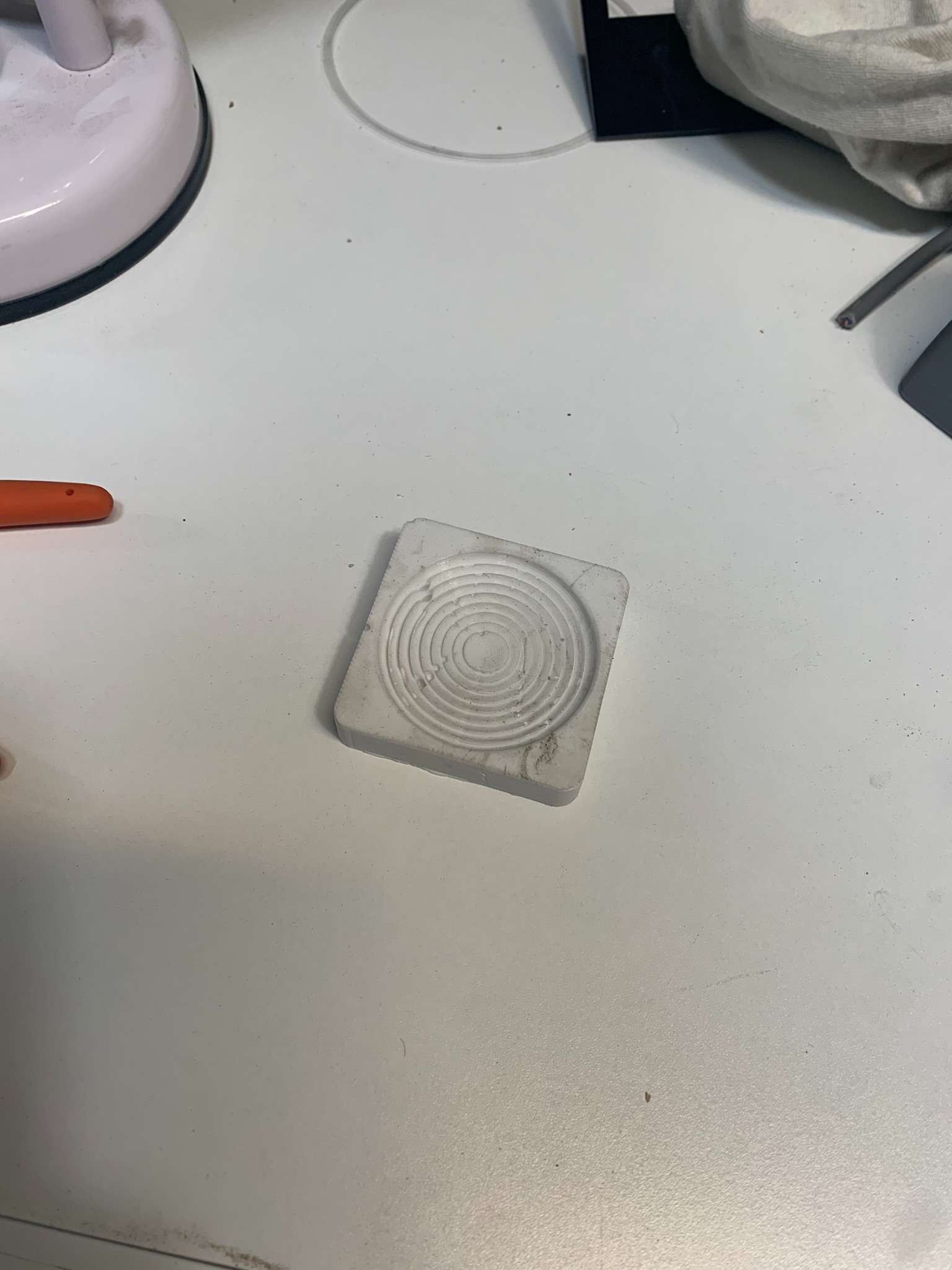
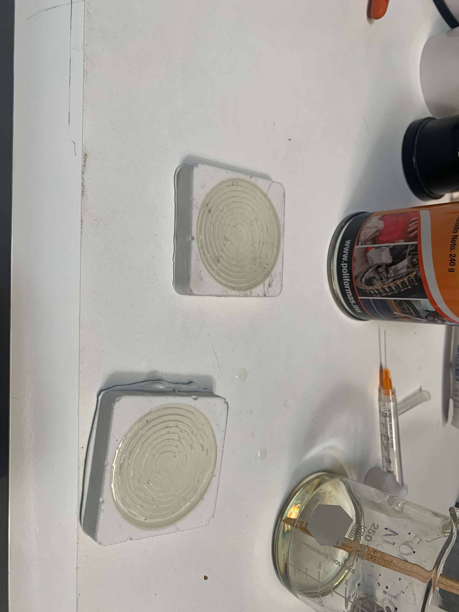
I again prepared 100mL of silicon with the 3mL of catalyzer, but now with an added 10mL of dilutant. The mixture got inmediately less viscous, so I poured everything on a new mould I prepared, as I didn't want to risk any contamination from previous attempts.
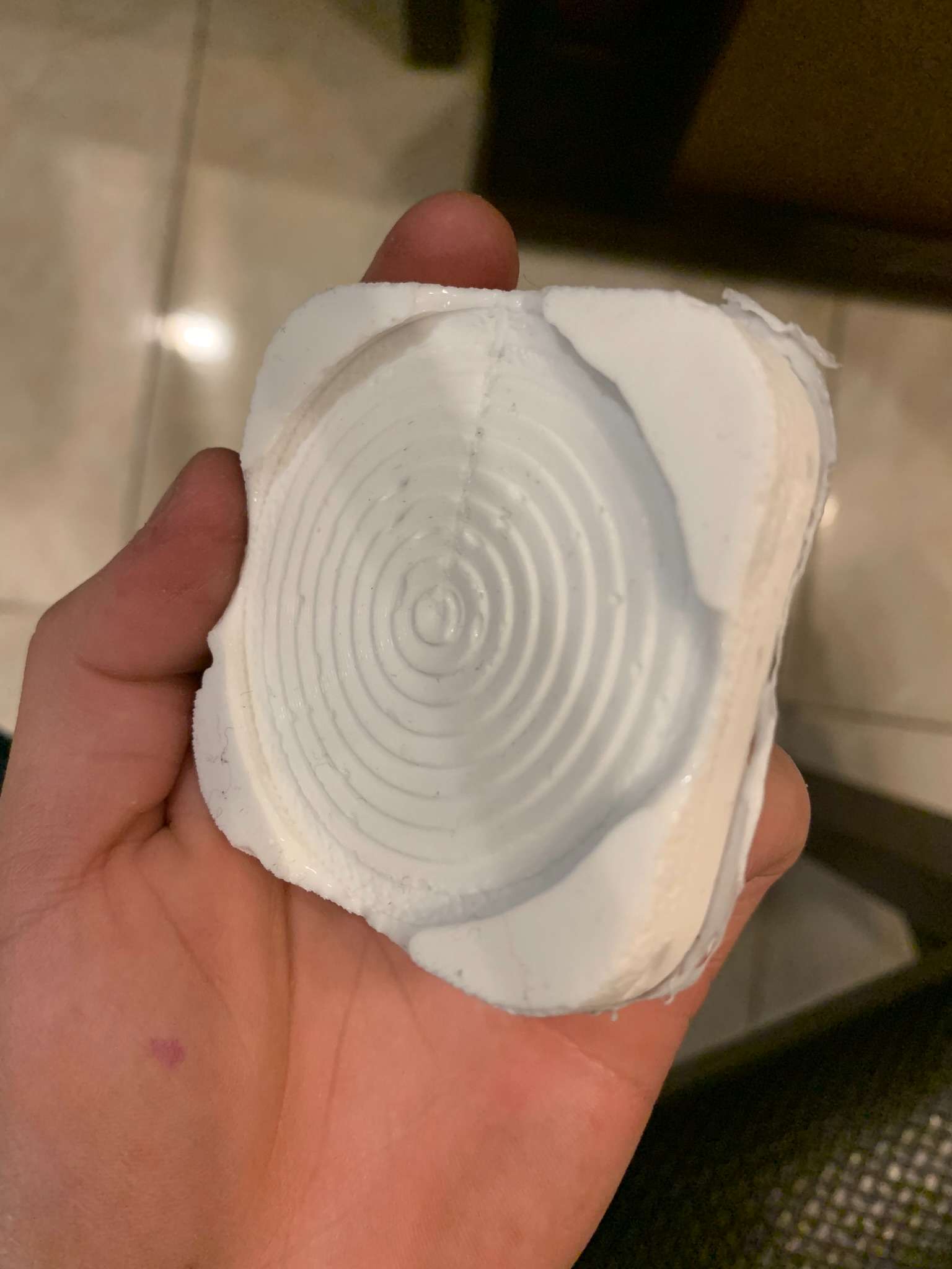
It solidified in roughly the same time as the previous mixture, but this time it delivered better results! It still had some bubbles, but I think that was from the way I was pouring the silicon mixture. I decided to ignore this and to continue trying to develop my casting.
Now that I has a usable silicon mould, I could then continue with casting some clear resin with it.
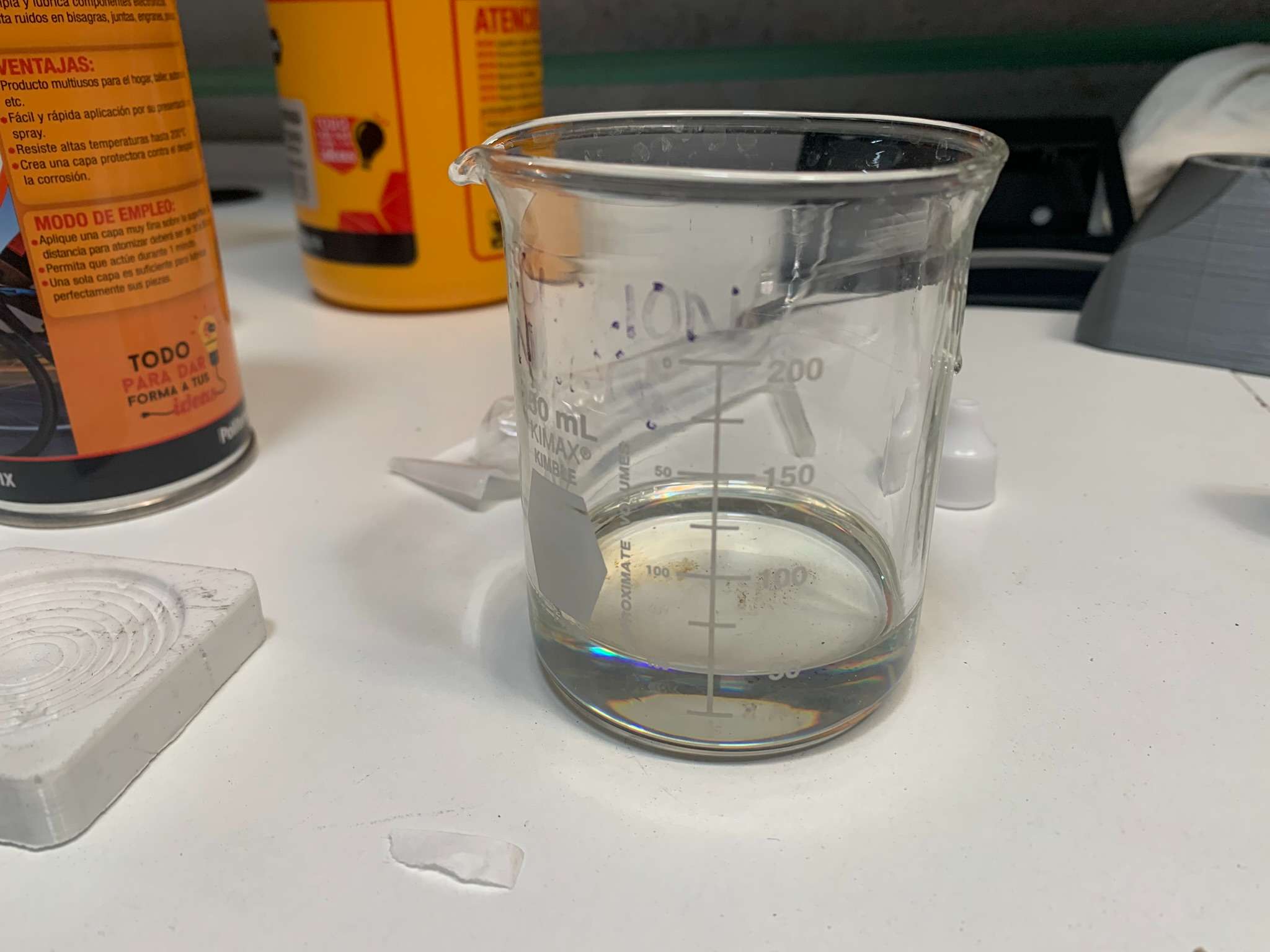
I purchased some clear polypropylene resin from the same manufacturer, whose instructions for the product indicate that a 2% concentration is mixed with the resin to activate it. So, again, using a syringe I measured 1 mL for a 50mL resin preparation, and thourougly mixed it using a wooden stick.
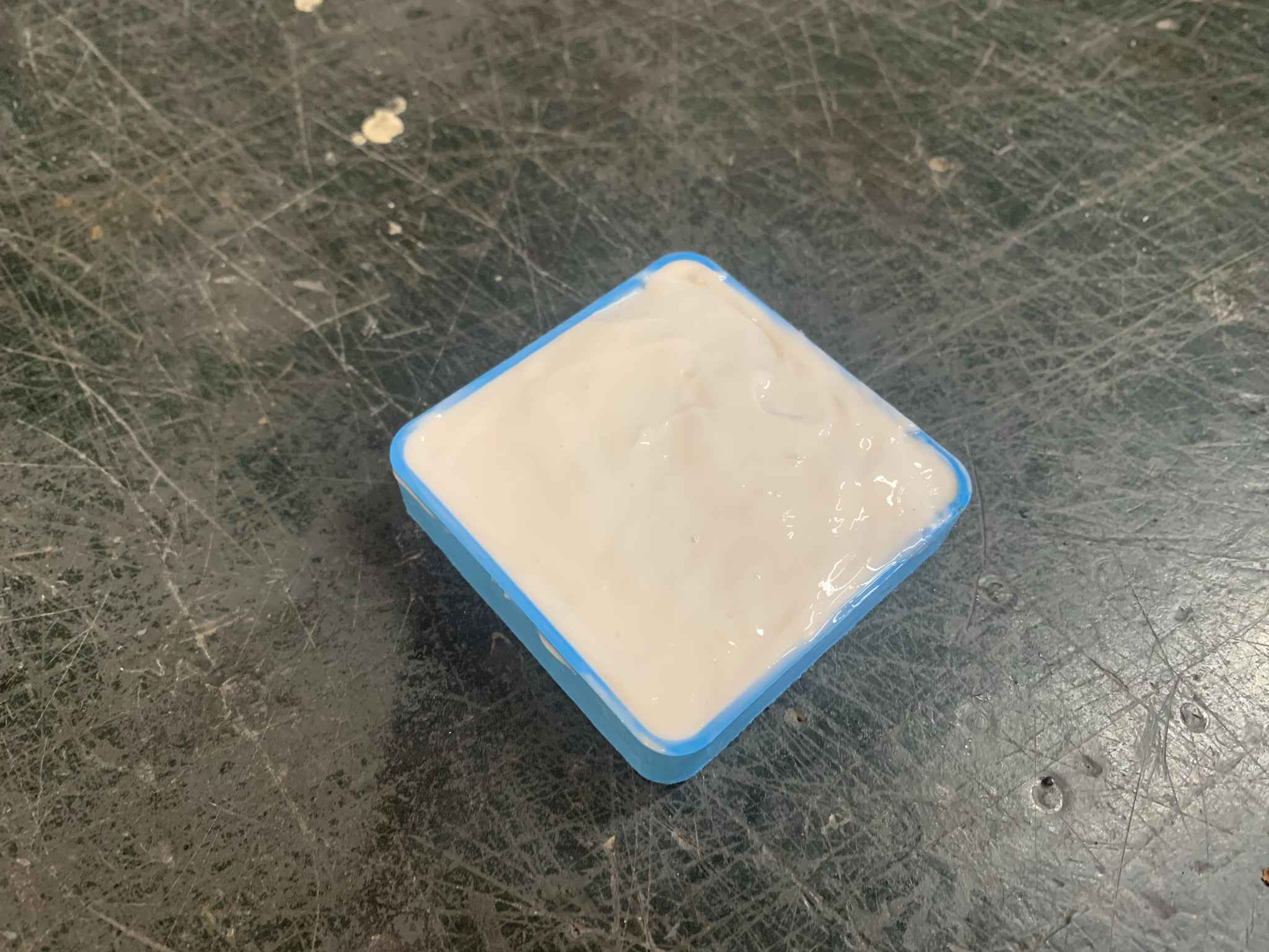
Once the resin mixture was ready, I poured it onto the finished silicon mould, but not before applying some silicon lubricant to it to ensure it would be easy to remove the piece after it has hardened. Once the resin was in the mould, I applied a little bit of "bubble remover" on the surface, which removed like magic the bubbles caused by the pouring process of the resin. Of course, the bubbles formed in the silicon mould stayed there.
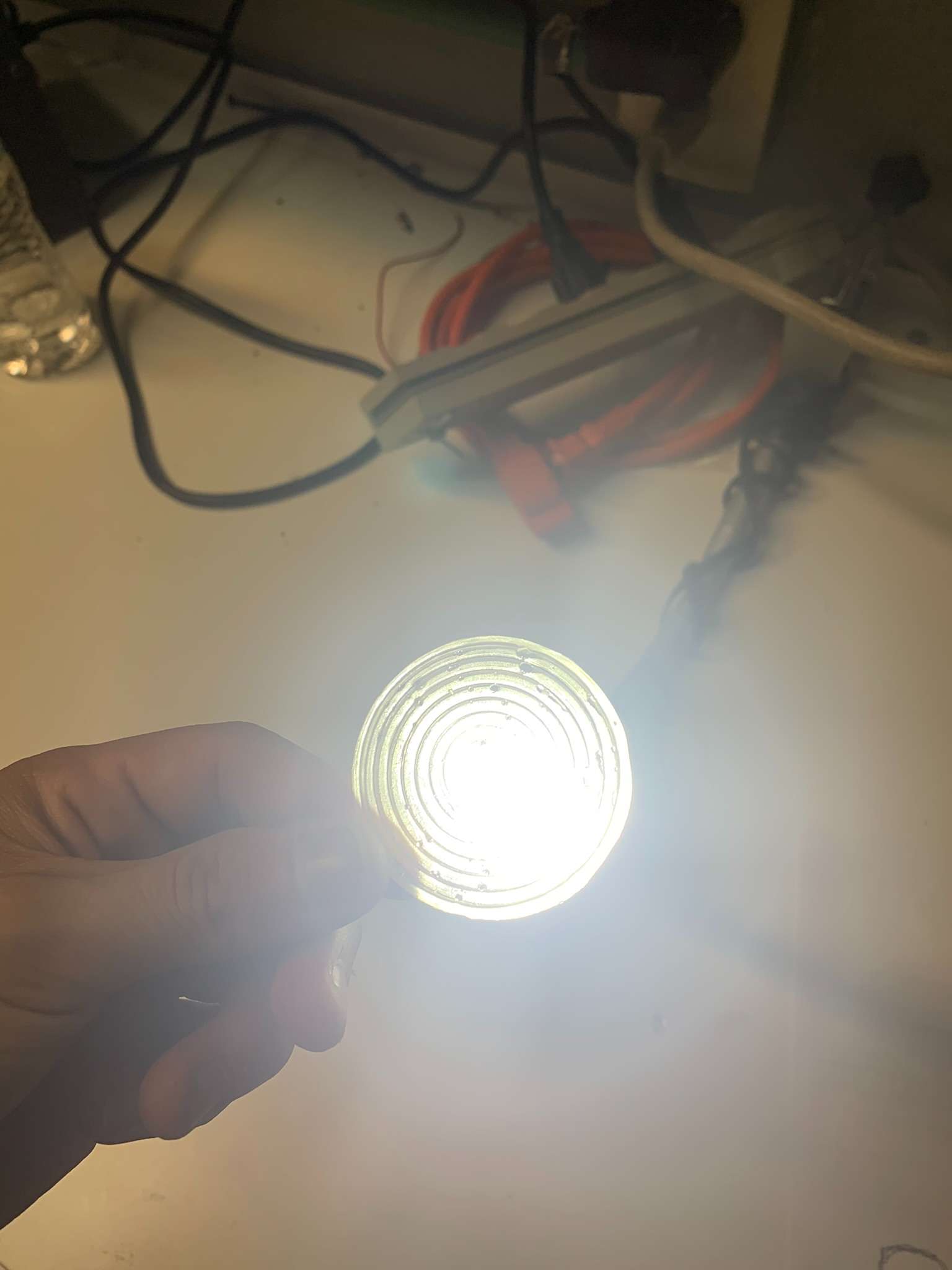
After 3 hours in the mould the resin had hardened enough for it to be safe to remove from the silicon. The piece turned out better than I expected! If I shined some light through it, I easily obtained the effect I was looking for if the light was located at the specified focus point.

Thank you for taking a look into my 12th week's progress!