
8. Electronics Design
I this week's assignment I was able to design and fab a "game console" arrangement as a continuation of a previous week's work.
Intentions:
In this week's work I want to implement my snake game previously made on week six into a different microcontroller architecture , and incorporate phisical buttons for the game..
To do this I devised the following, fairly simple, schematic:
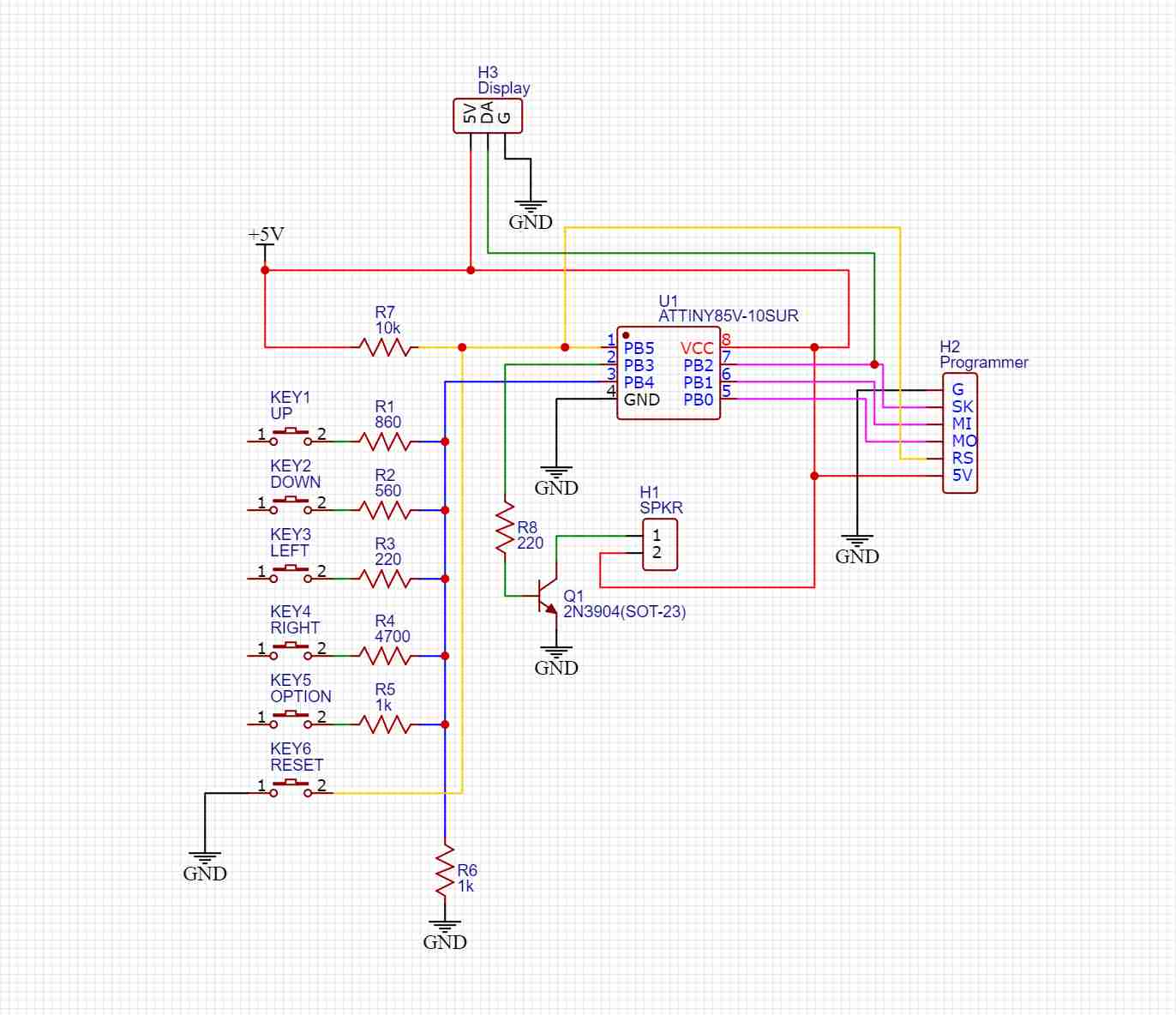
The circuit is based around the ATTiny85 microcontroller made by Atmel. It packs a punch for its size, but is severely more restricted both in GPIO interfaces, memory and computing power that the much more powerful, modern (and expensive) RP2040 mounted in the XIAO board I used before. Nevertheless, with some optimization of my original program for the snake game, the ATTiny85 should be more than capable of executing it along the 8 x 8 neopixel array display.
However, the first limitation for my application is GPIO. If I want to control 5 buttons along the neopixel signal output, a speaker to produce sound and a reset button, the ATTiny simply doesn't have enough inputs to handle all that directly, so we have to get a little creative.
Both the speaker and the data pin for the neopixel display cannot be avoided, but we can implement all 5 game input buttons onto one single pin by using it as an analog input and make every button a voltage divider with a different voltage output. To do This I placed a common 1K resistor for all the buttons and a different resistor value for each button, that when connected, create a specific voltage output onto the connected pin that can be measured using the onboard Analog to Digital converter (ADC), which transforms an analog voltage value from 0 to 5V to a digital 8-bit value onto the microcontroller, value which ranges from 0 to 1023. As we don't have a native serial interface for debugging and reading the values from the voltage dividers coming into the ADC, we can calculate the values we should expect at the input and their tolerances to program the ranges on the MCU for them to trigger an specific action, without errors.
The first thing to do is to calculate the ADC value we should expect when pressing a specific button, according to what resistor it activates. To do this we use this formula:

Now we have to calculate a tolerance range for our measurements, because the circuit will not behave exactly as we calculated, due to external noise, soldering and trace patterns, and the inherent value tolerance expected from the installed components. To account for this I used this other formula, where we insert a tolerance value and we obtain the uppper And lower range limits for our conditionals inside the program. Using a 5% tolerance usually works fine.

An alternative (sometimes easier) method, is to take a multimeter and measure each divider's voltage and use that to calculate an approximate range for the ADC inputs, but if you don't have a multimeter, the previous method works fine!
Designing the PCB:
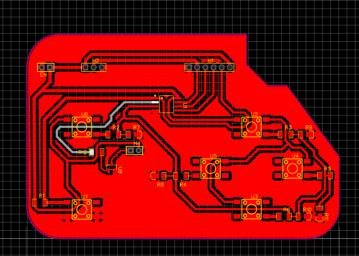
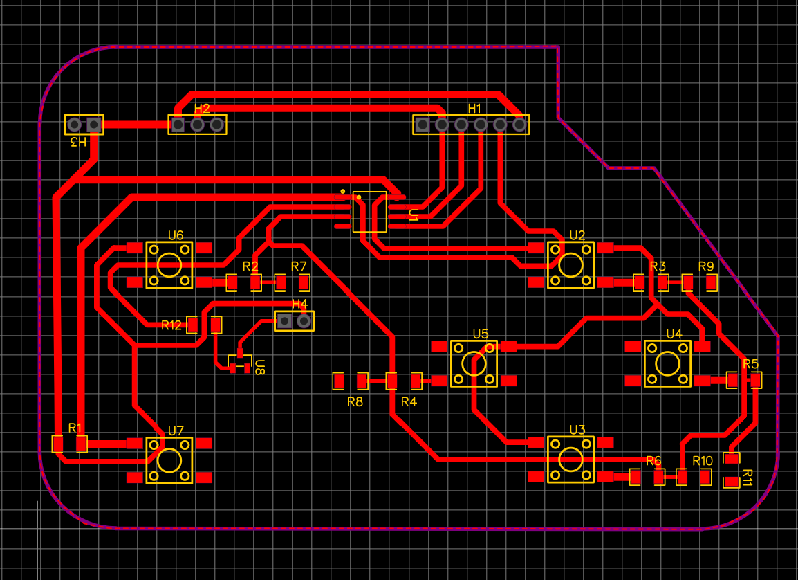
I again used EasyEDA to design my PCB, the power traces are this time a little wider, as they will be carrying more current to feed all the connected lamps. Except for the pin headers, the screw terminals and the DC barrel jack, every component is meant to be sufrace mounted.
Once every trace was made, I added teardrops to every pad in order to create stronger connections when fabbing the board, also, I like to include a general ground plane using the empty spaces of the board, this makes connecting grounds easier and reduces unwanted noise in the circuit.
Board Fabbing:
I was really curious about fabbing a PCB using the CO2 laser cutter, I know the CO2 laser cutter we have cannot cut metal, not even a tiny layer like the one in phenolic boards, but what if it could be used at least to create the pattern for the traces?
With that alternative in mind I sanded the board to remove as many of its reflectiveness as I could and then painted it using some black spray paint I found laying around. The idea was to use the laser to remove the paint in the places where copper wasn't meant to be.
I uploaded the exported PNG image from EasyEDA of the board into the laser cutter's software, which in this case was Lightburn. I made sure that the board's dimensions were correct, and started configuring the laser to a 80% maximum power, 100mm/s feed speed and two passes. The image was already a negative, so no need to invert it in Lightburn.

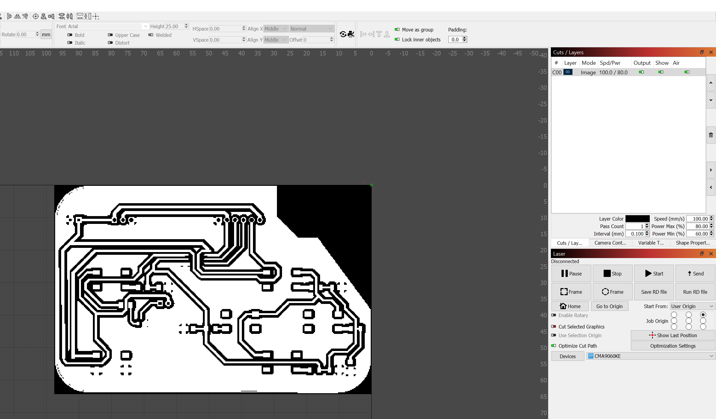
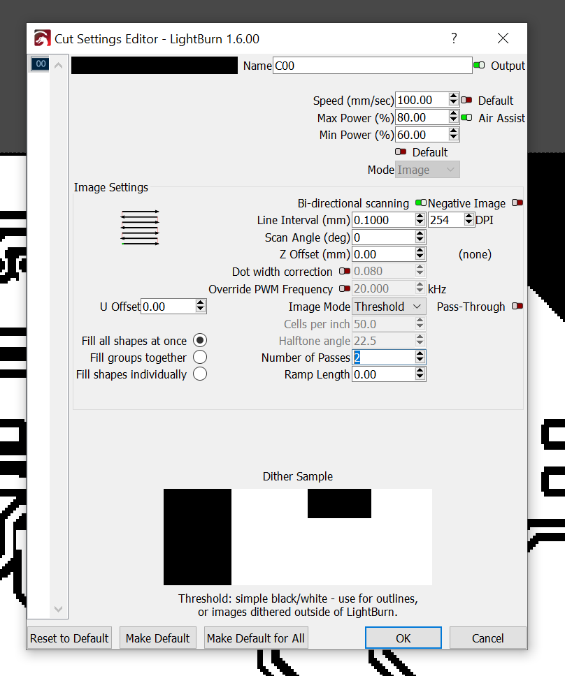
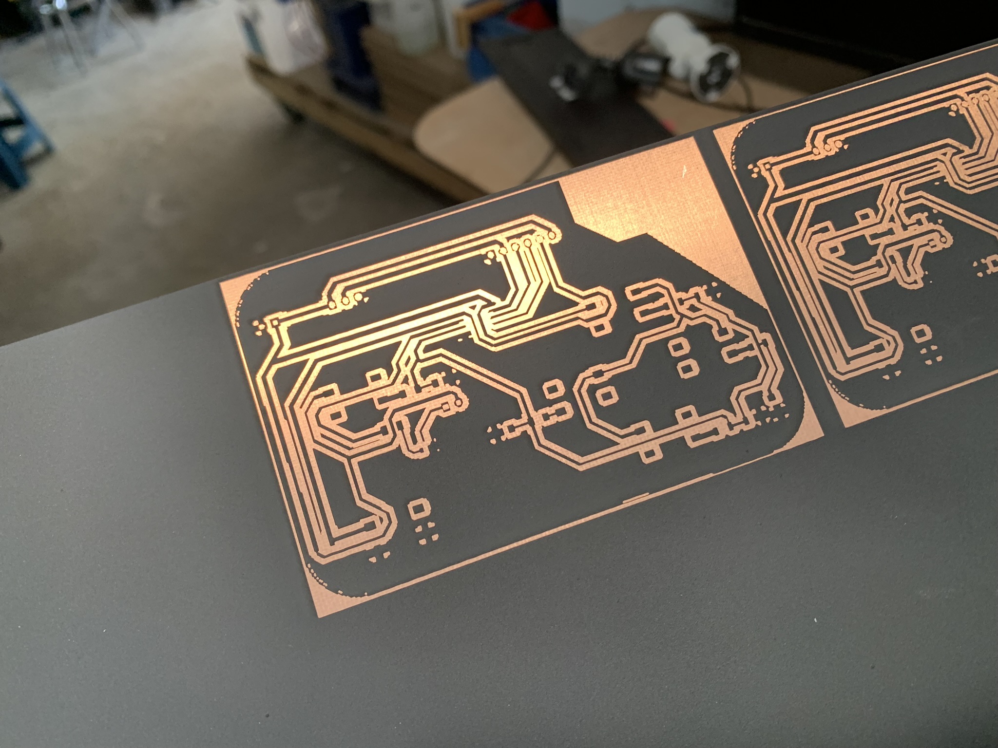
Lightburn automatically interprets images as engravings, and two passes using this process showed the best results rather than increasing power or decreasing the engraving speed; the first pass removes almost all of the paint and the second gets rid of everything hidden on the surface's crevices, allowing the unwanted copper to remain fully exposed.
The result is shown on the image below:
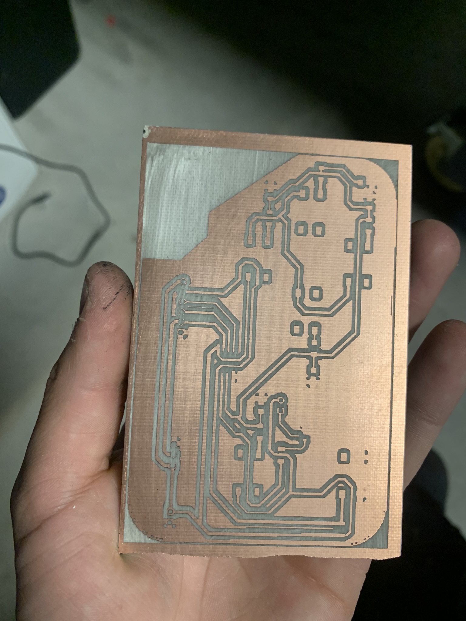
To remove the unwanted copper, I used a traditional etching process using a Ferrous Chloride solution at 40°C. (I know this process is not advisable, but I really wanted to know if this would work). After three hours on the plastic tray with the etching solution, I removed the board and wiped the paint using some paint thinner, leaving it looked like this:
The mini-mill does the holes needed for you and cuts the board out of the remaining material, but in this case all of this was manual labor. I started by drilling the holes using a mounted drill and a 1/16th of an inch drill bit, then with care and precision I was able to drill the holes needed for this board, then I had to cut the board's outline, so I could be left with just a single piece. To do this I used a DREMEL rotary tool with a cutting disc installed. I then quickly gave up as my only cutting disk broke into pieces.
Soldering & Programming:
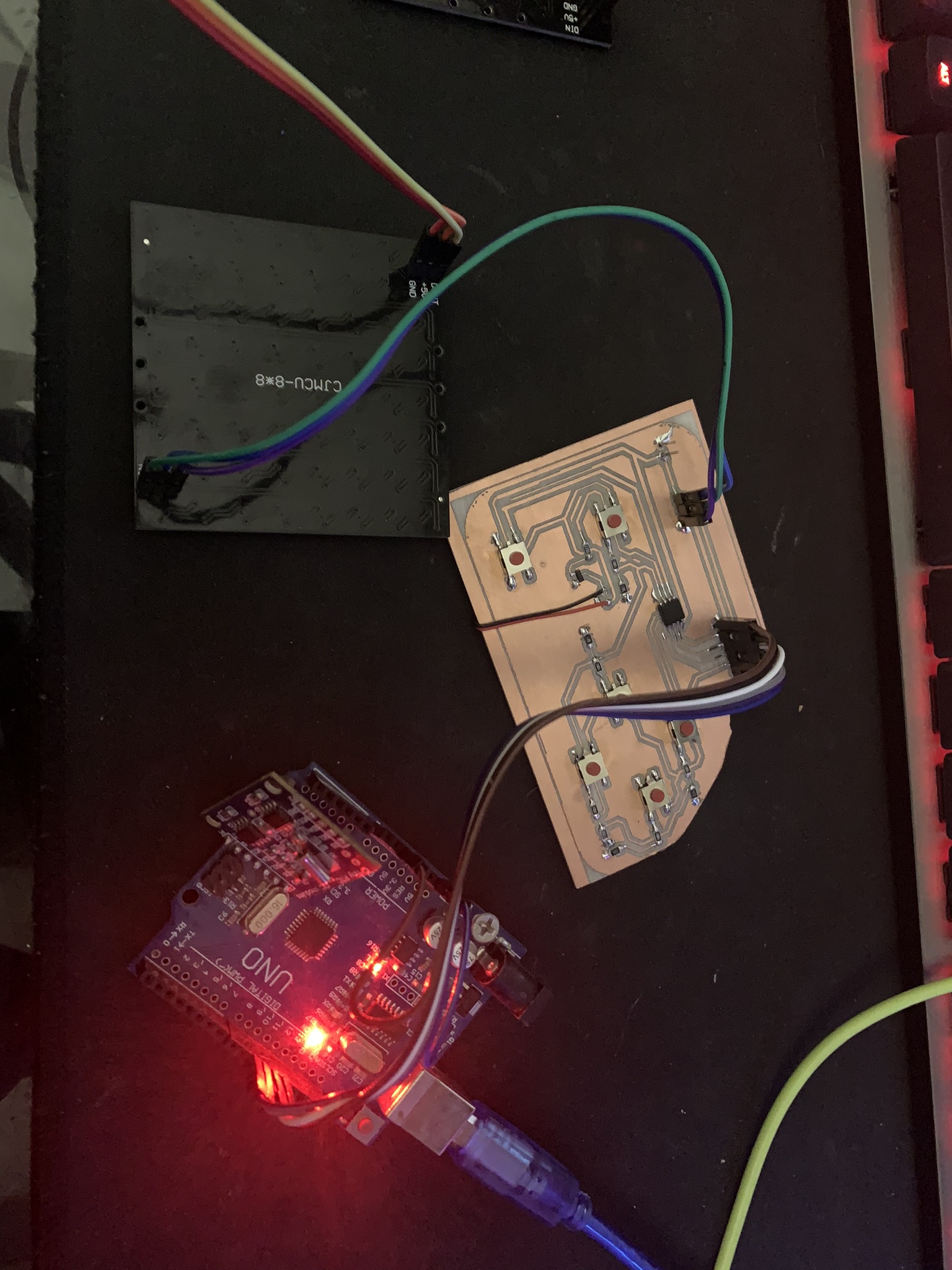
I started by soldering the resistors, followed by the pushbuttons, the (very) small transistor and the speaker. The last things soldered were the ATTiny85 microcontroller, because it is the most delicate, and the pin headers, because they tend to be kinda uncomfortable to have on the board while soldering everything else. The finished board looked like this with everything connected:
Once the soldering job was done, it was time to try and program the microcontroller.
MCU Programming:
Programming a soldered microcontroller with no support circuitry like an arduino board has is a little trickier than simply plugging the board to a USB port and calling it a day. As there's no interpreter between the USB and UART or SPI protocols like a traditional arduino board habits we have to use an external adapter, which in this case, ought to be an Arduino UNO board. To convert that board into a Serial Programmer, we need to upload the sketch under the name "Arduino as ISP", this way we can turn the board into a programmer for our ATTiny microcontroller. You can find that sketch under the "Examples" category inside Arduino IDE.
Once the code is uploaded we have to make the following connections, the ones already made in the previous picture but shown in detail below:
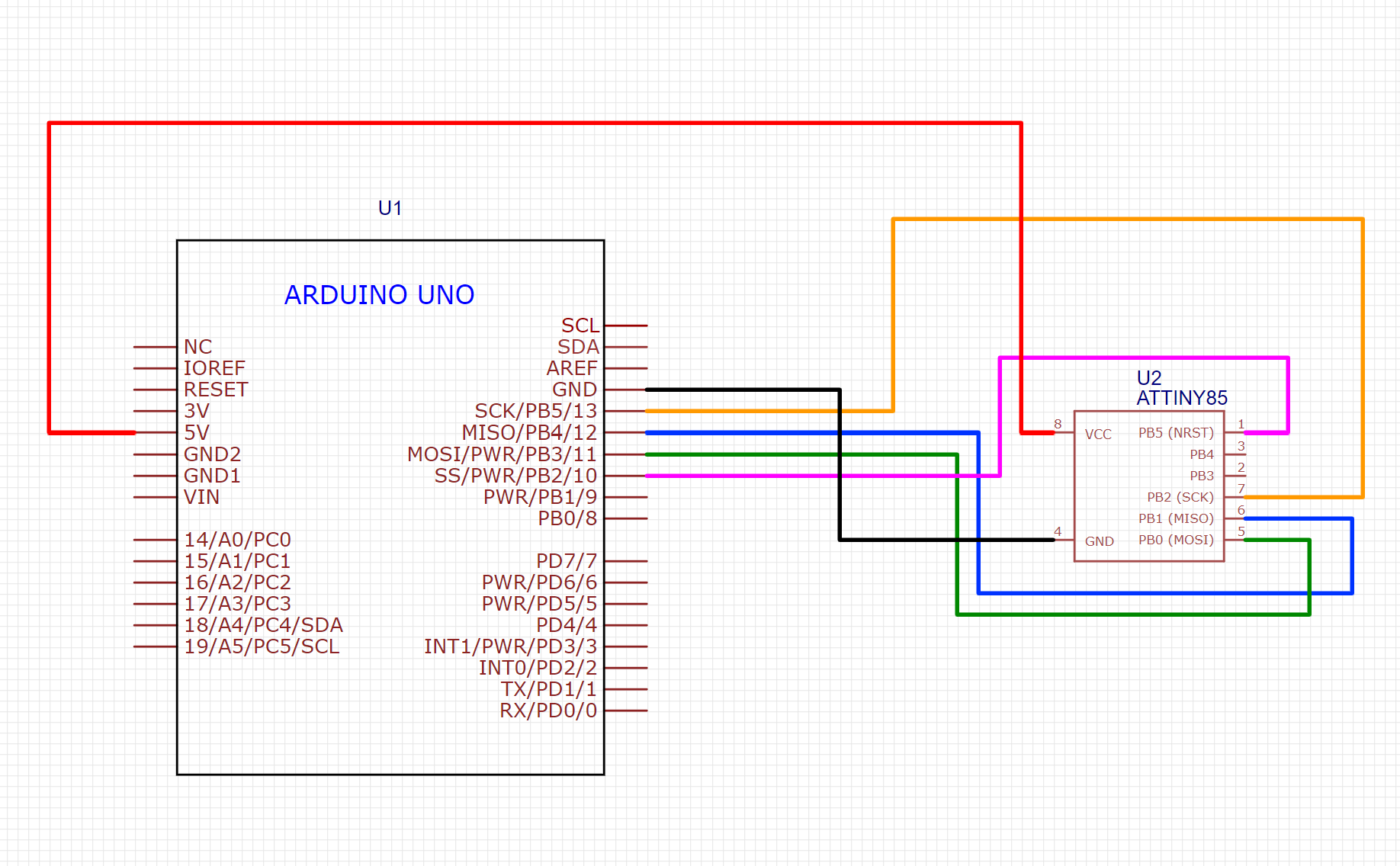
What we're connecting here is an SPI bus, a Serial protocol commonly used for ISP (In-System Programming) of different microcontroller architectures. In this case, the ATTiny85 doesn't include an integrated UART pinout and doesn't support UART programming natively, and while it is technically possible to incorporate that functionality using the "Micronucleus" Bootloader, I really don't need it for any reasons beyond debugging and at least for me and this specific application, is not worth the effort and extra memory usage, because yeah, program memory is quite limited on this microcontroller, it has only 8KB that can run out very quickly!
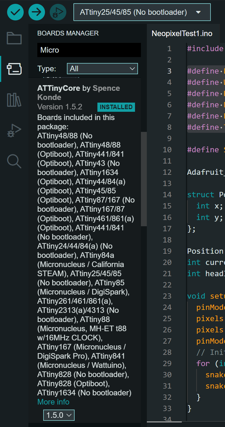
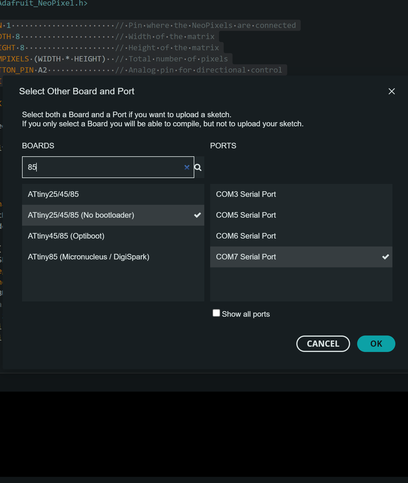
Now, if we want to be able to program the ATTiny85 under the Arduino IDE environment we have to install the microcontroller's specific hardware support into the IDE, in this case I will be using the ATTiny Core library by Spence Konde. To install it simply look for it in the boards manager menu on the left side of the Arduino IDE's GUI, then we look for the ATTiny 85 in the available newly installed microcontrollers. Remember to choose the Serial port where the programmer board is connected!
Because the ATTiny85 has a lot less memory capacity than the XIAO RP2040 board I used earlier to run the Snake game, because of this I had to optimize the code a lot. The following was the code I uploaded to the ATTiny:
	#include Adafruit_NeoPixel.h

	#define PIN_NEOPIXEL 1
	#define NUM_NEOPIXELS 64
	#define ROWS 8
	#define COLS 8
	#define BUTTON_PIN A2
	#define BUZZER_PIN 3
	#define MAX_SNAKE_LENGTH 32

	Adafruit_NeoPixel strip = Adafruit_NeoPixel(NUM_NEOPIXELS, PIN_NEOPIXEL, NEO_GRB + NEO_KHZ800);

	struct Position {
		uint8_t x, y;
	};

	Position snake[MAX_SNAKE_LENGTH];
	uint8_t snakeLength = 1;
	Position apple;
	uint8_t currentDirection = 0;
	unsigned int gameSpeed = 250;  // Initial game speed is 250ms
	unsigned int Brightness = 0;

	void setup() {
		pinMode(BUTTON_PIN, INPUT);
		pinMode(BUZZER_PIN, OUTPUT);
		strip.begin();
		strip.show();
		strip.setBrightness(10);
		snake[0] = { COLS / 2, ROWS / 2 };
		randomSeed(analogRead(0));
		generateApple();
	}

	void loop() {
		unsigned int buttonRead = analogRead(BUTTON_PIN);

		if (buttonRead > 550 && buttonRead < 580) currentDirection = 1;       // Up
		else if (buttonRead > 630 && buttonRead < 680) currentDirection = 2;  // Down
		else if (buttonRead > 810 && buttonRead < 850) currentDirection = 3;  // Left
		else if (buttonRead > 490 && buttonRead < 520) currentDirection = 4;  // Right
		else if (buttonRead > 140 && buttonRead < 210) {                      // Select
		Brightness++;
		if (Brightness > 3) {
			Brightness = 0;
		}
		switch (Brightness) {
			case 0:
			strip.setBrightness(25);
			break;
			case 1:
			strip.setBrightness(50);
			break;
			case 2:
			strip.setBrightness(75);
			break;
			case 3:
			strip.setBrightness(100);
			break;
		}
		delay(100);
		}

		updateSnake(currentDirection);
		delay(gameSpeed);

		if (snake[0].x == apple.x && snake[0].y == apple.y) {
		if (snakeLength < MAX_SNAKE_LENGTH) {
			snakeLength++;
			playTone(1000, 200);  // Play a tone when the apple is eaten
			if (snakeLength == 5) {
			playLevelUpMelody();  // Play level-up melody exactly when reaching length 5
			gameSpeed = 150;      // Speed up the game
			}
		}
		generateApple();
		}

		if (checkSelfCollision()) {
		playLosingMelody();
		flashRed(3);
		restartGame();
		}
	}

	void updateSnake(int direction) {
		Position nextHead = snake[0];
		switch (direction) {
		case 1: nextHead.y = (nextHead.y - 1 + ROWS) % ROWS; break;
		case 2: nextHead.y = (nextHead.y + 1) % ROWS; break;
		case 3: nextHead.x = (nextHead.x - 1 + COLS) % COLS; break;
		case 4: nextHead.x = (nextHead.x + 1) % COLS; break;
		}

		for (int i = snakeLength - 1; i > 0; i--) {
		snake[i] = snake[i - 1];
		}
		snake[0] = nextHead;

		strip.clear();
		for (uint8_t i = 0; i < snakeLength; i++) {
		uint8_t idx = (i % MAX_SNAKE_LENGTH);
		strip.setPixelColor(snake[idx].y * COLS + snake[idx].x, i == 0 ? strip.Color(255, 255, 0) : (snakeLength >= 5 ? strip.Color(0, 0, 255) : strip.Color(0, 255, 0)));
		}
		strip.setPixelColor(apple.y * COLS + apple.x, strip.Color(255, 0, 0));
		strip.show();
	}

	void playTone(unsigned int frequency, unsigned int duration) {
		unsigned long period = 1000000L / frequency;
		unsigned long length = duration * 1000L;
		for (unsigned long i = 0; i < length; i += period) {
		digitalWrite(BUZZER_PIN, HIGH);
		delayMicroseconds(period / 2);
		digitalWrite(BUZZER_PIN, LOW);
		delayMicroseconds(period / 2);
		}
	}

	void playLevelUpMelody() {
		unsigned int melody[] = { 523, 587, 659, 698, 784 };         // Frequencies for C5, D5, E5, F5, G5
		unsigned int noteDurations[] = { 100, 100, 100, 100, 100 };  // Note durations in milliseconds
		for (uint8_t i = 0; i < 5; i++) {
		playTone(melody[i], noteDurations[i]);
		delay(50);  // Pause between notes
		}
	}

	void playLosingMelody() {
		unsigned int melody[] = { 440, 392, 349, 330, 294 };         // Frequencies for A4, G4, F4, E4, D4
		unsigned int noteDurations[] = { 200, 200, 200, 200, 200 };  // Durations for each note
		for (int i = 0; i < 5; i++) {
		playTone(melody[i], noteDurations[i]);
		delay(50);  // Pause between notes
		}
	}

	void flashRed(uint8_t count) {
		for (uint8_t i = 0; i < count; i++) {
		for (uint8_t j = 0; j < NUM_NEOPIXELS; j++) {
			strip.setPixelColor(j, strip.Color(255, 0, 0));
		}
		strip.show();
		delay(500);
		strip.clear();
		strip.show();
		delay(500);
		}
	}

	bool checkSelfCollision() {
		for (uint8_t i = 1; i < snakeLength; i++) {
		if (snake[i].x == snake[0].x && snake[i].y == snake[0].y) return true;
		}
		return false;
	}

	void generateApple() {
		do {
		apple.x = random(COLS);
		apple.y = random(ROWS);
		} while (isOnSnake(apple.x, apple.y));
	}

	bool isOnSnake(uint8_t x, uint8_t y) {
		for (uint8_t i = 0; i < snakeLength; i++) {
		if (snake[i].x == x && snake[i].y == y) return true;
		}
		return false;
	}

	void restartGame() {
		snakeLength = 1;
		currentDirection = 0;
		snake[0] = { COLS / 2, ROWS / 2 };
		gameSpeed = 250;  // Reset to initial speed
		generateApple();
		strip.clear();
		strip.show();
	}
As you can see, compared to the previously made snake code, this one here uses more specialized variable structures that help optimize the code a lot.
The last step is to upload the code, but we can't use the normal upload button to do it. Instead, we have to use the option "Upload Using Programmer" under the "Sketch" menu:
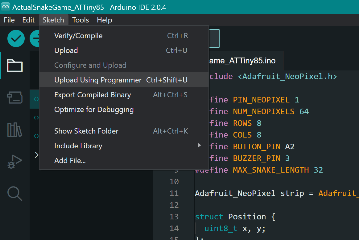
If everything is connected right and the code has no errors, the upload process should end briefly, and in my case result in the snake game code working perfectly!
Thank you for taking a look into my 8th week's progress!