
5. 3D Printing and Scanning
On this week's assignment I was able to scan and print a 3D object I modeled not using a CAD software, but another interesting approach I really wanted to try: Clay modeling!
Modeling with Clay:
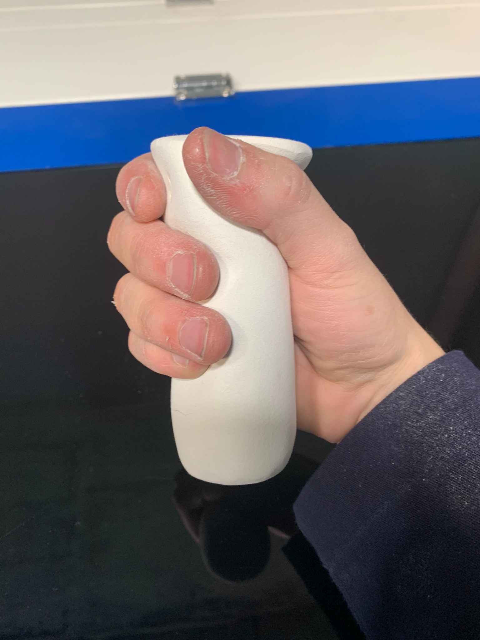
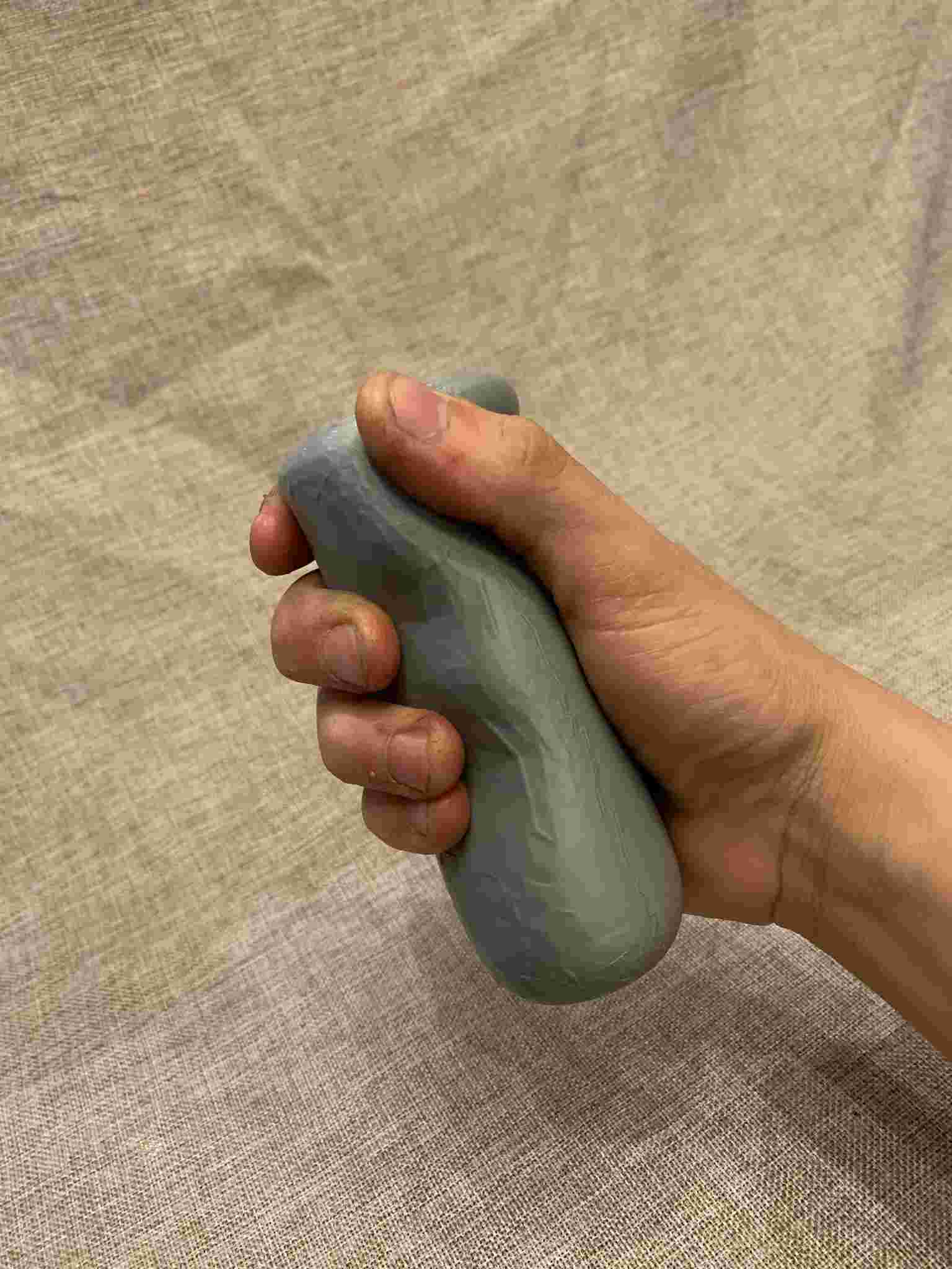
I wanted to create a handle piece for my final proyect, which needed to be ergonomic so the scooter I intend to create gets some extra points for comfort. Designing ergonomic objects tends to be complicated, specially with parametric CAD software, so I decided to try a different approach: What if I used clay to model my handle design? Using my own hands as reference to mold the piece ergonomically, as I am able to actually feel the design and make changes in real time!
Well, it was certainly easier said than done. I started by going to the arts supply store to get some modeling clay, in my case I bought "DAS" branded clay, which is air-drying and pretty easy to work with, making it perfect for my intentions.
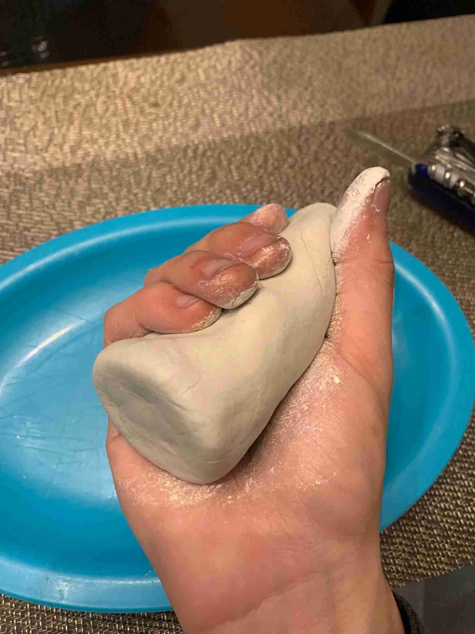
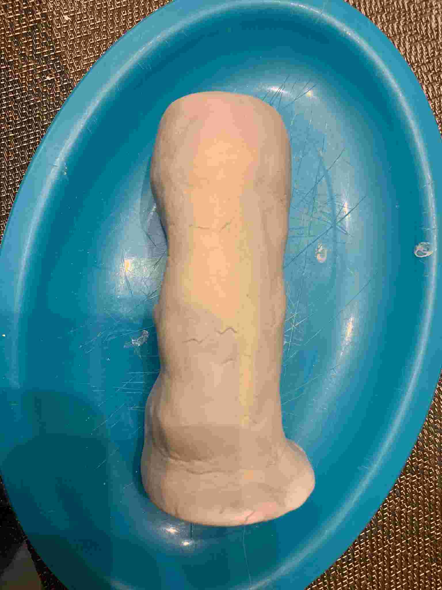
I took a good chunk of clay and squeezed it with my hand to give it an elongated shape, which also had the shape of my hand.
Of course I can't just shape the handle exactly off my hand and call it a day, it might be comfortable, but only for me. As all hands are not the same, I modeled the clay into a more "Generic" and adaptable shape that is still comfortable to hold.
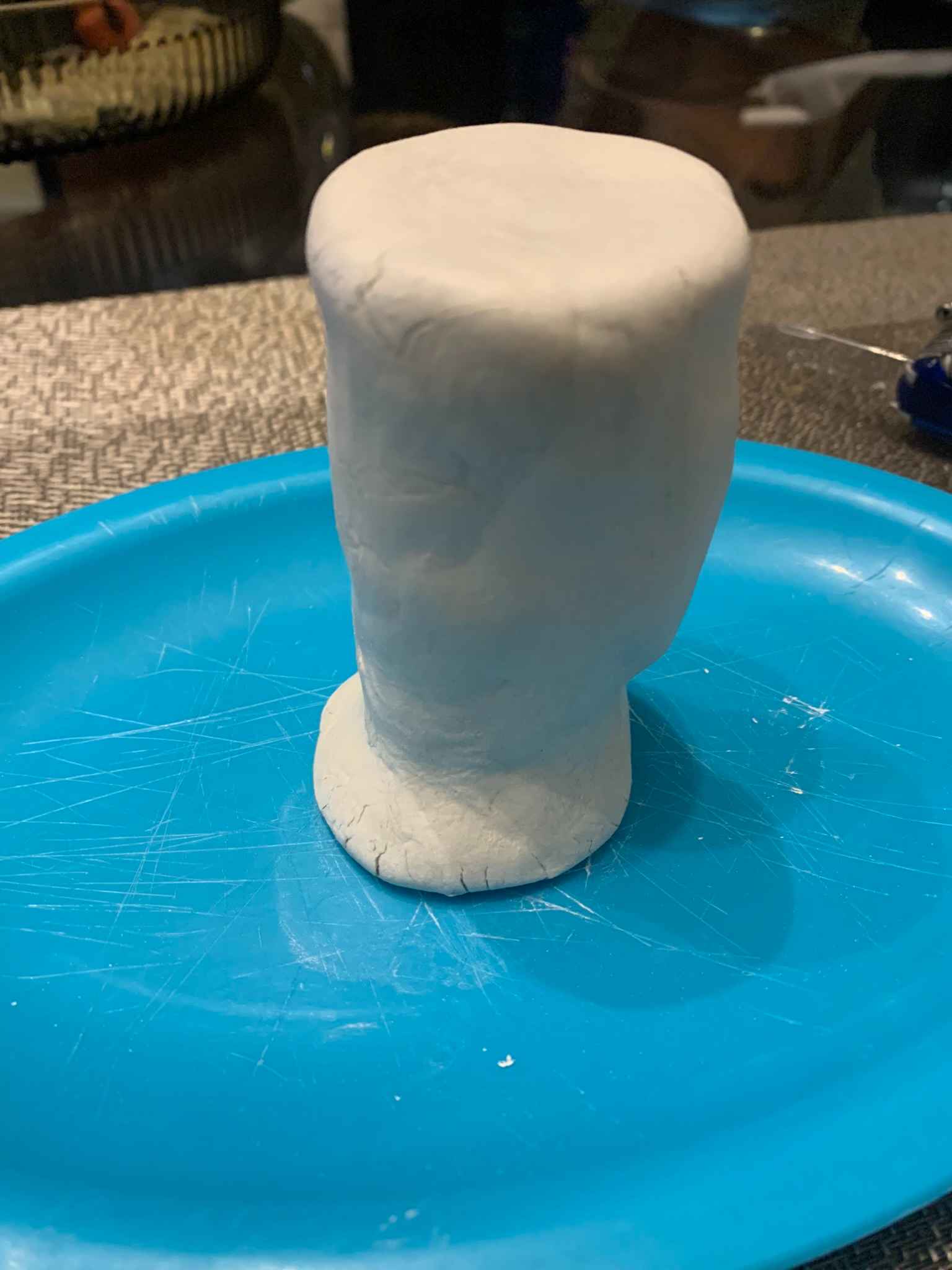
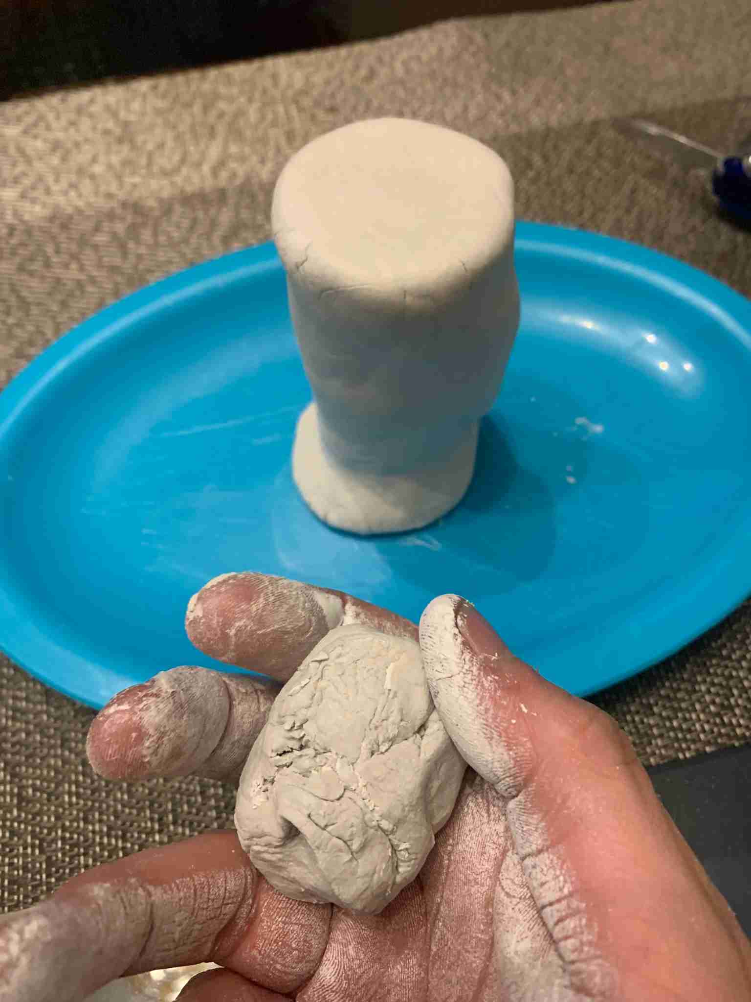
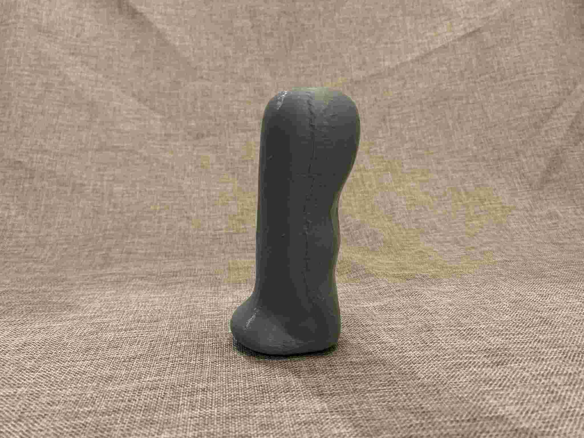
When looking at it, it seemed to be missing something on top, so I took another chunk of clay and modeled a round addition to the model, leaving me with what is shown on the left, yes I know, it is not very pretty but trust me on this. I had then to wait for it to dry up, which took around 12 hours in ambient temperature.
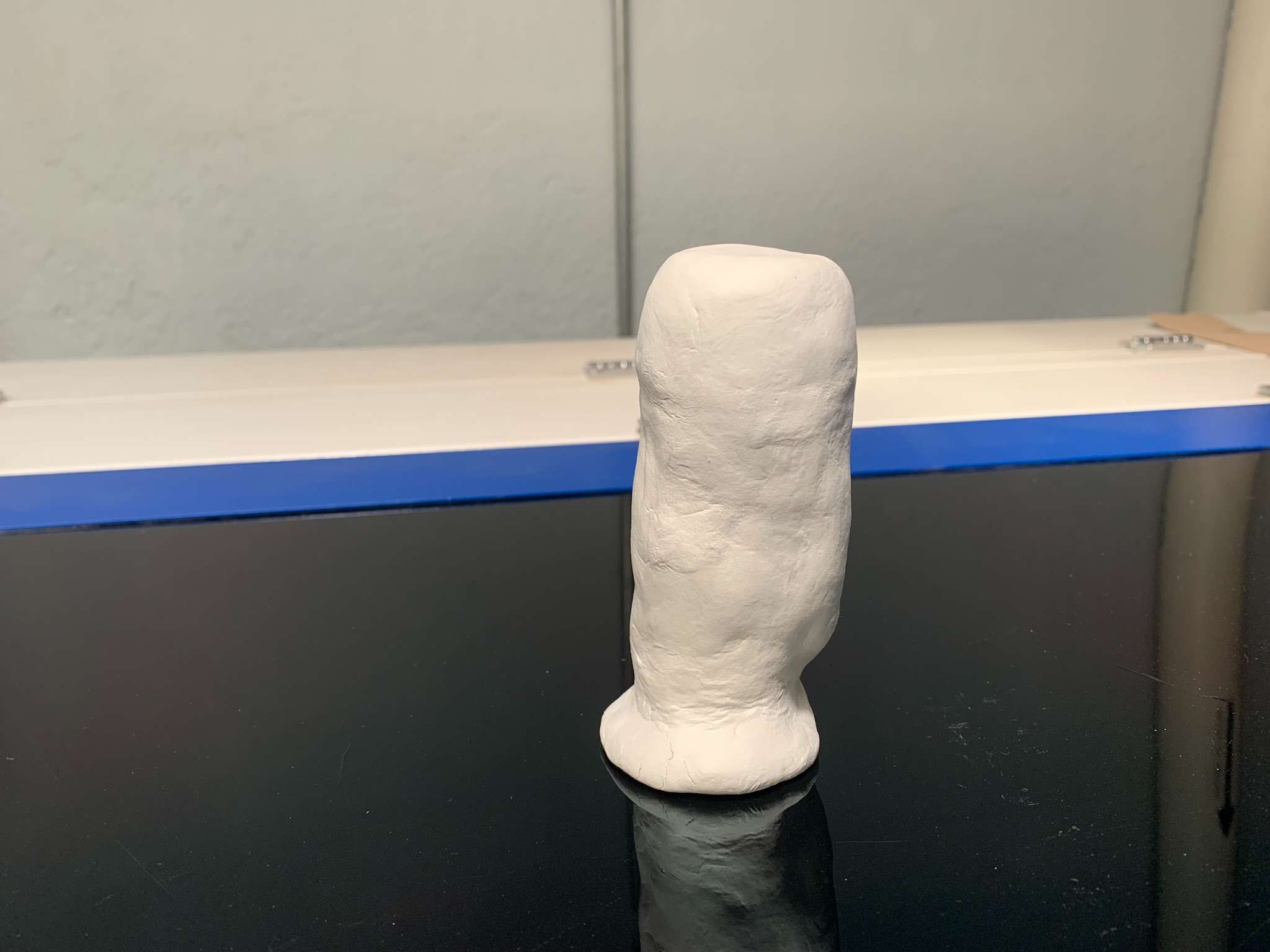
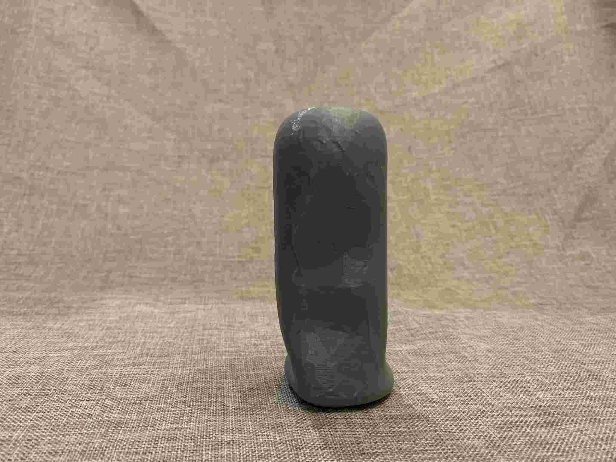
Once it dried I sanded it using a fine sandpaper, with the purpose of removing all the ugly imperfections my questionable clay-modeling skills left all around the piece. It really made a difference, also helping me accentuate the ergonomy and generalize it for its use with different kinds of hands:
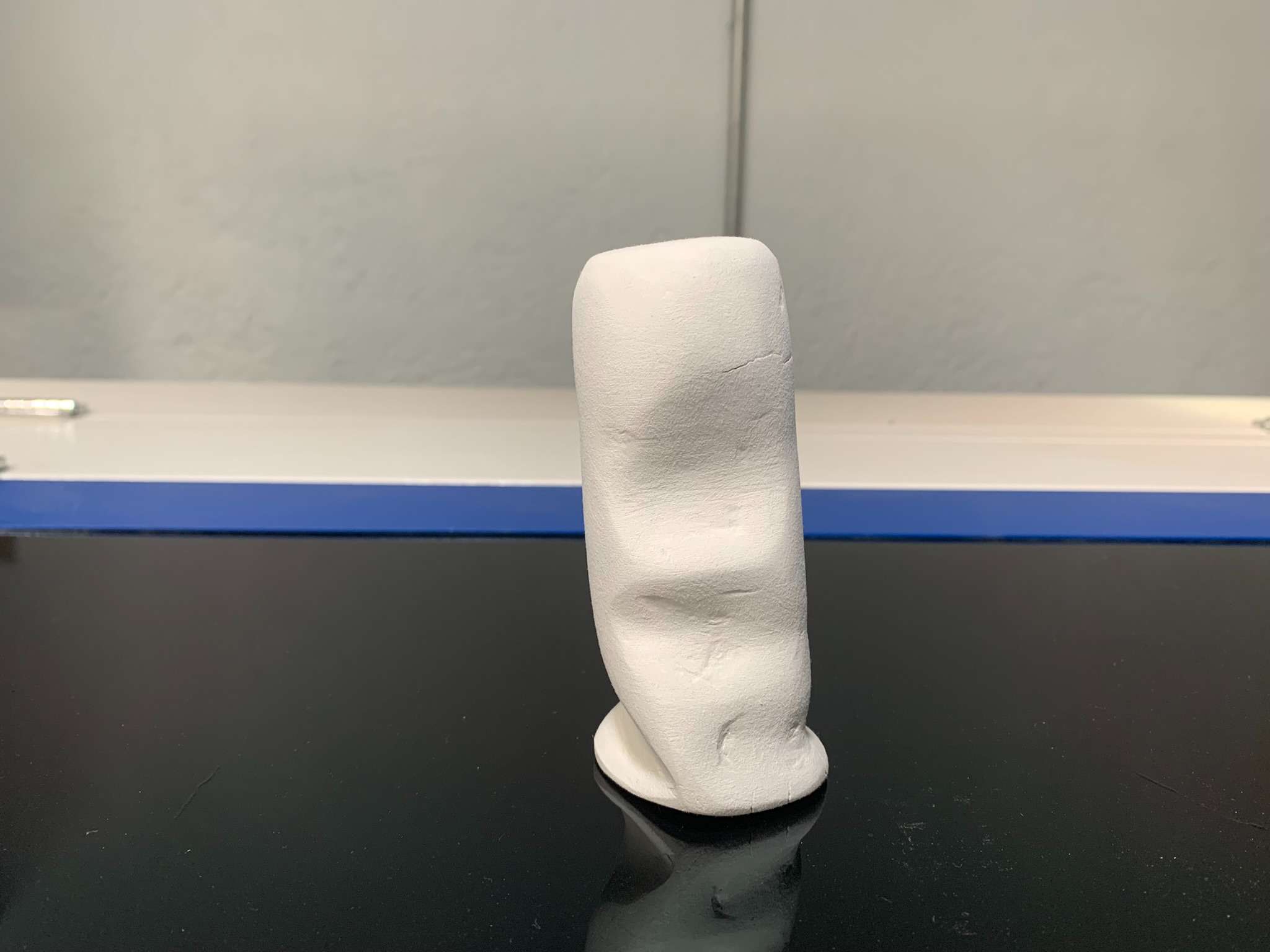
The handle was looking good, so when I was finally convinced with the clay model it was time to scan it!
3D Scanning:
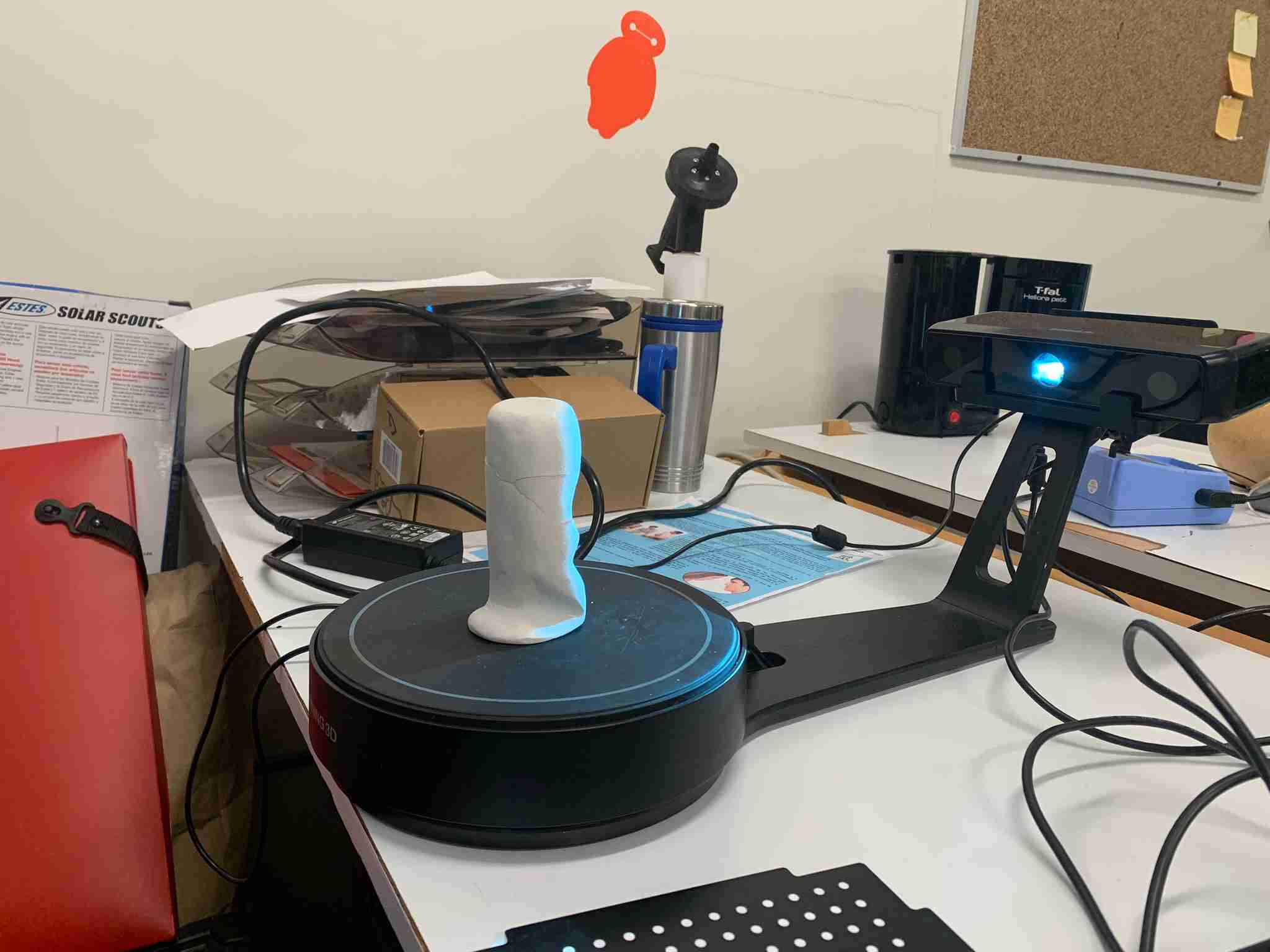
To scan the object we used a specialized 3D scanner from Shining3D. It has a rotating table and a double depth sensing camera system which results in very high resolution 3D scans.
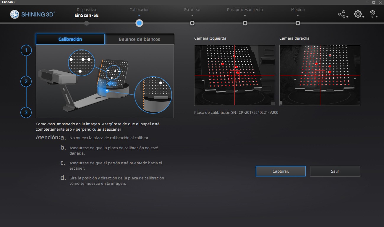
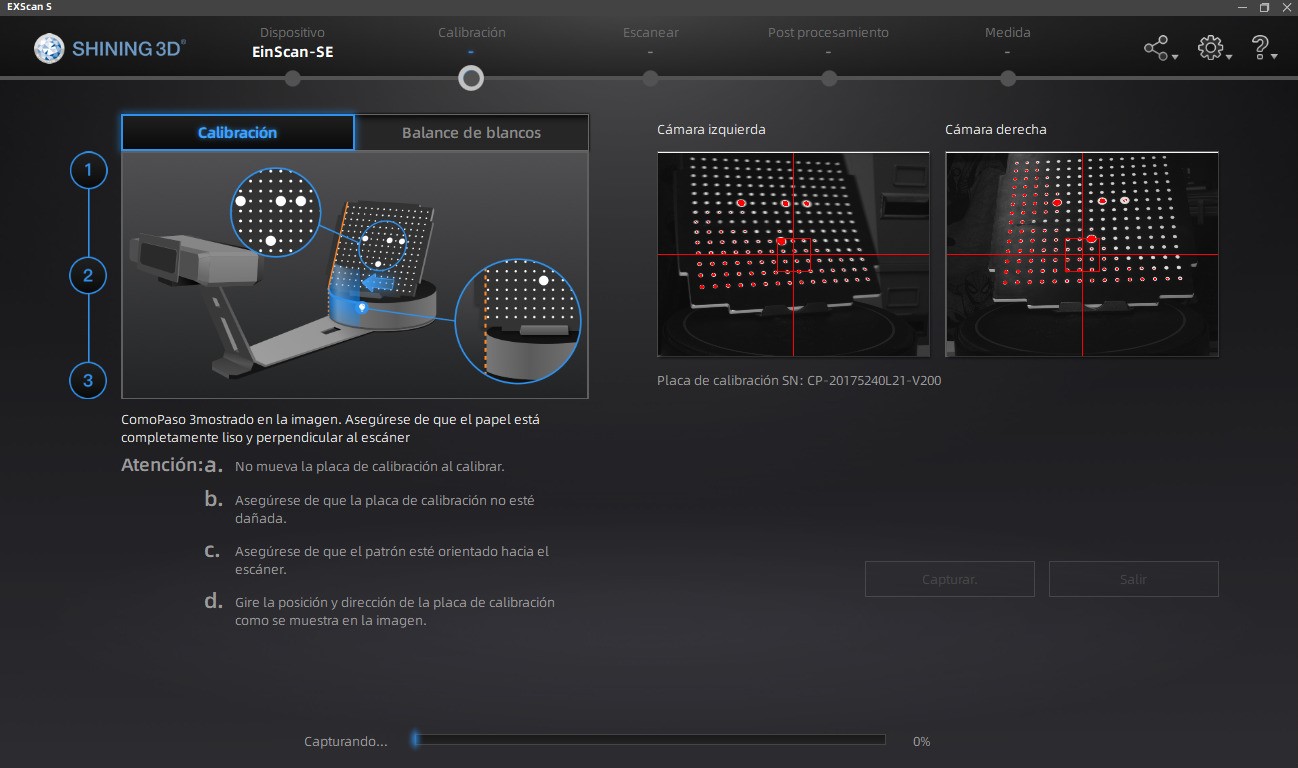
Before using it though, we have to calibrate it, by following the steps shown on the scanner's software, which basically tell you to align dots on the screen shown over a live feed of the cameras, with a calibration pattern on the turntable. Every time you turn on the scanner to use it, you have to go through the calibration process.
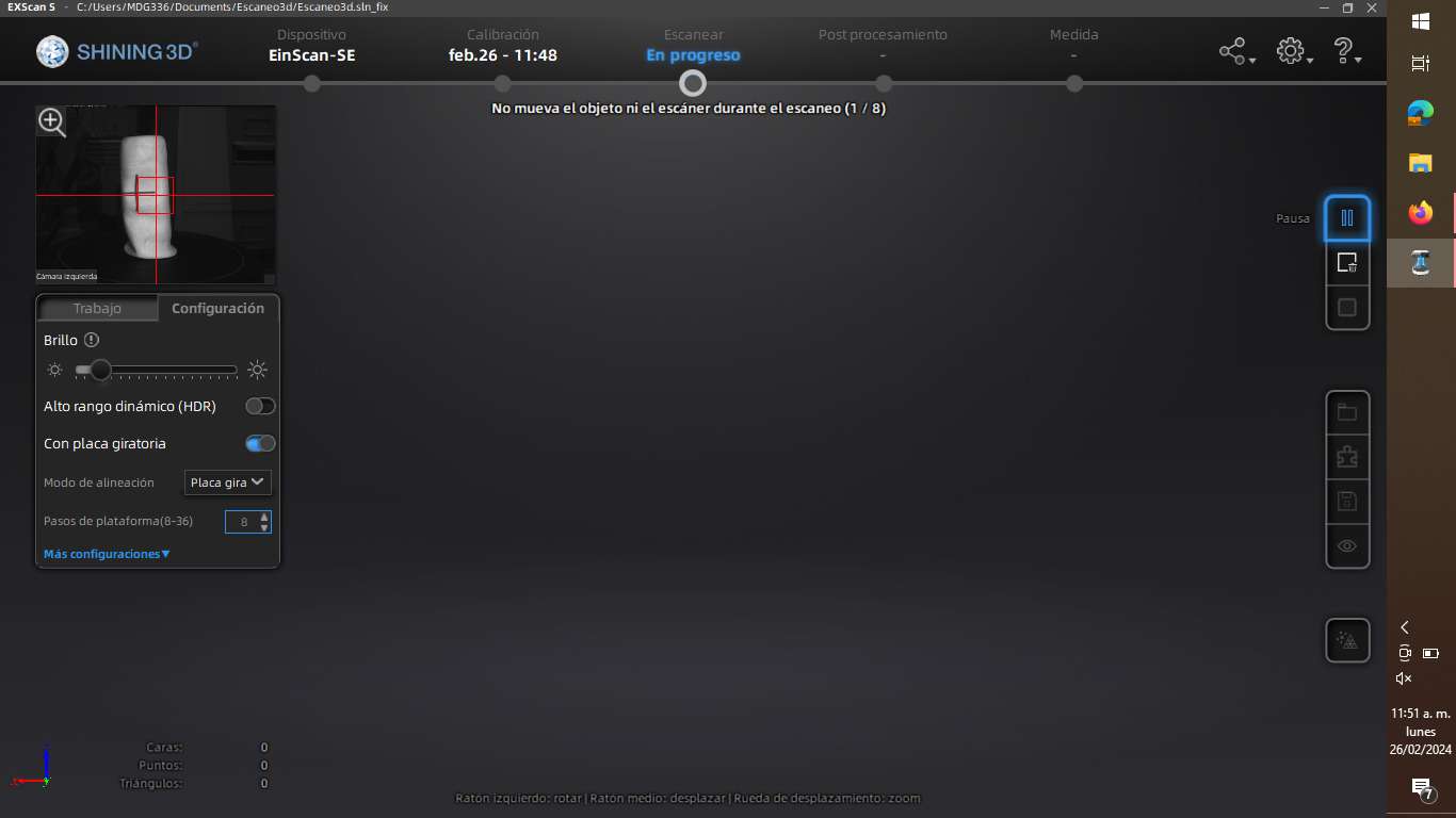
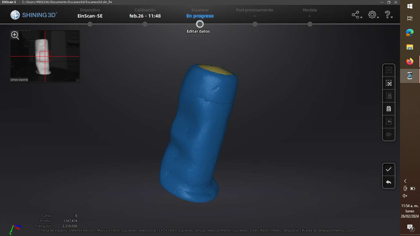
We can now place the object we want to scan onto the turntable, the camera's live feed on the computer screen will help us center the object correctly, so the scanning process is succesful. Once we hit the "Start Scan" button, a line proyection will show over the model, as well the turntable will start spinning in little steps. The number of steps the turntable takes to a full rotation can be configured: More steps mean more scanning data, which means more detail, which also carries more processing time and a higher file size.
Once the scan is completed we will obtain the 3D model's data, which inside the scanner's software can be converted into many mesh-based 3D file formats. As I was going to 3D print the result, I chose the .stl format.
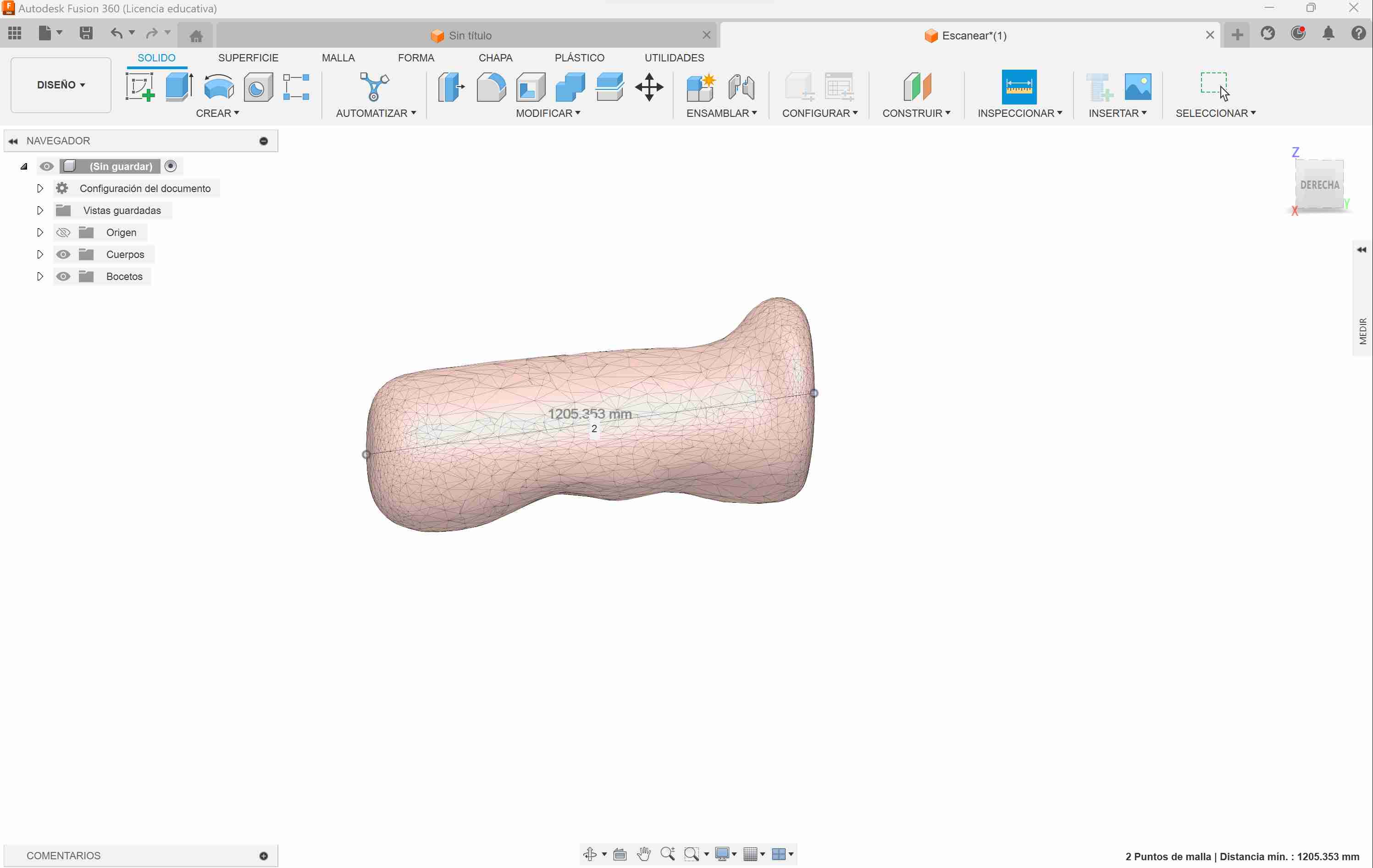
As you can see, the high resolution capabilities of the scanner played against me. The scanner was able to pick up all the nooks and crannies of the clay model, something that certainly was not desirable. So I opened the .stl file on Fusion 360 and reduced by an order of magnitude the mesh resolution of the model, resulting in a very softened texture. I also checked with the measuring tool that the dimensions were correct, which they were!
3D Printing:
Once I was satisfied with the digitized 3D model of my handle piece, it was time to print it in a more durable and permanent material, such as the PLA filament we have widely available in our FABLAB.
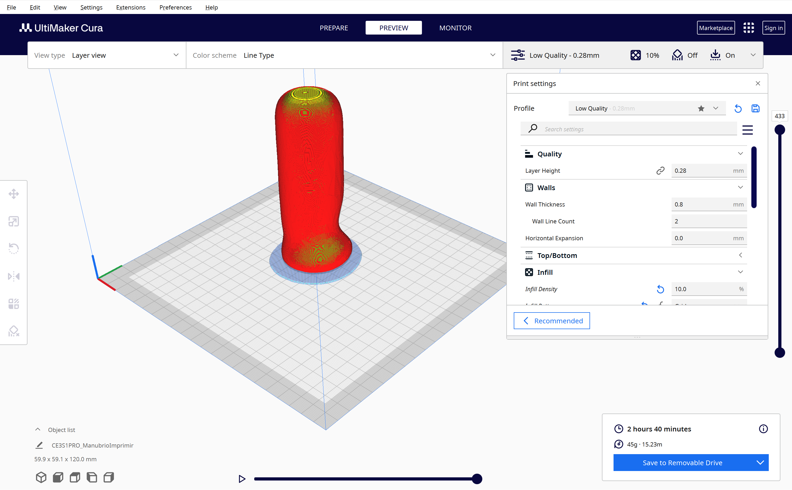
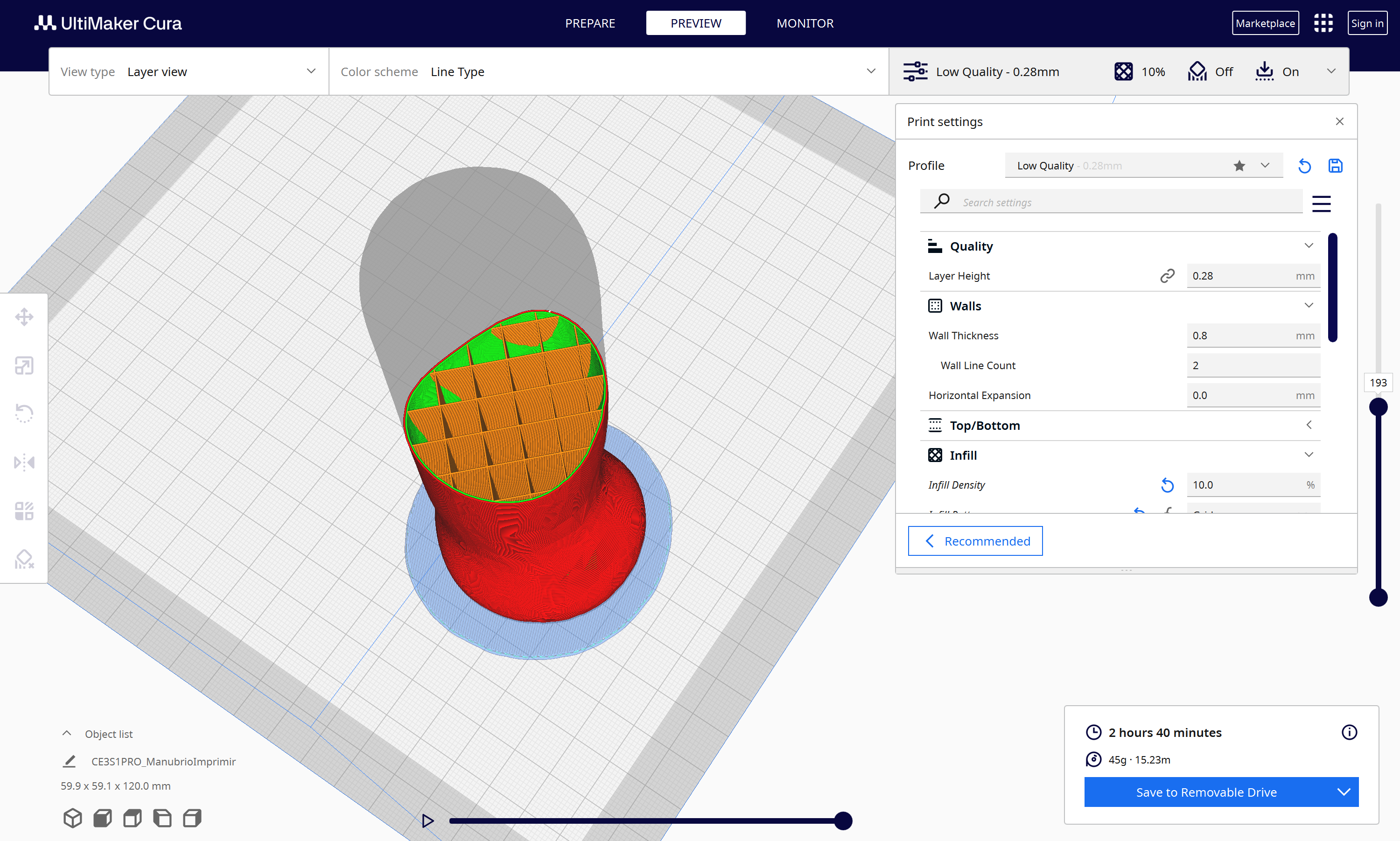
Every 3D print starts with the slicing process, a transformation of the 3D model into the G-Code the printer can actually understand. This is done by dividing the model into "Slices" of configurable width (hence the name), so the printer can work its way up, layer by layer, depositing material and building the object. The inside of the object is usually not completely solid, but made of configurable patterns that give structure to the printed piece. Different patterns and filling densities offer various mechanical properties, but, as this object is just a test and will not be submitted to any kind of stress, I just chose a 10% filling density and the most common grid pattern approach, with the intention of reducing printing time.
Other very important parameters when 3D printing are: Speed, Slice height, Extruder temperature and Bed temperature. The first parameter refers to how fast the extruder will move to create your object; move it too slow, and your print will take an eternity to finish, move it too fast and the printing quality will be affected, to the point it might fail completely. In my case using a speed of 50mm/s was the sweet spot between print time and print quality.
Slice height is another important parameter, as it directly affects both printing time and printing quality. A higher slice height will result in faster but lower quality prints, and viceversa. It is important to remember that if configured too high, the layers wont stick to each other, and if configured too low, the filament wont have space to extrude. Those maximums and minimums depend on the size of the extruding tip.
The extruder and bed temperatures are directly related to the material we will be printing with: Different materials require different configurations, in my case I used PLA filament, and configured the extruder temperature to 210°C and the bed temperature to 70°c.
The slicing process in my case is made using the software "Ultimaker Cura", a free to use, very powerful 3D printing software that has support for dozens of 3D printers, incluiding the Ender S3 Pros we have in our FABLAB.
To slice a model just import it onto Cura, look for your printer in the provided database, choose the printing parameters and click "Slice". Once the process is done, you can send it to print or save the file for later.
The print took 2 hours and a half to complete, as expected, and resulted in a shiny and soft surface. Printed in gray PLA plastic, the model resulted very light but resistant at the same time. And though I am not very talented for clay-modeling, this approach resulted in a interesting alternative to CAD in cases which we need to be in direct contact with the thing we're modeling.
3D Printing a Parametric Design:
Now for the next part, I wanted to print the following part that was designed parametrically using OnShape:
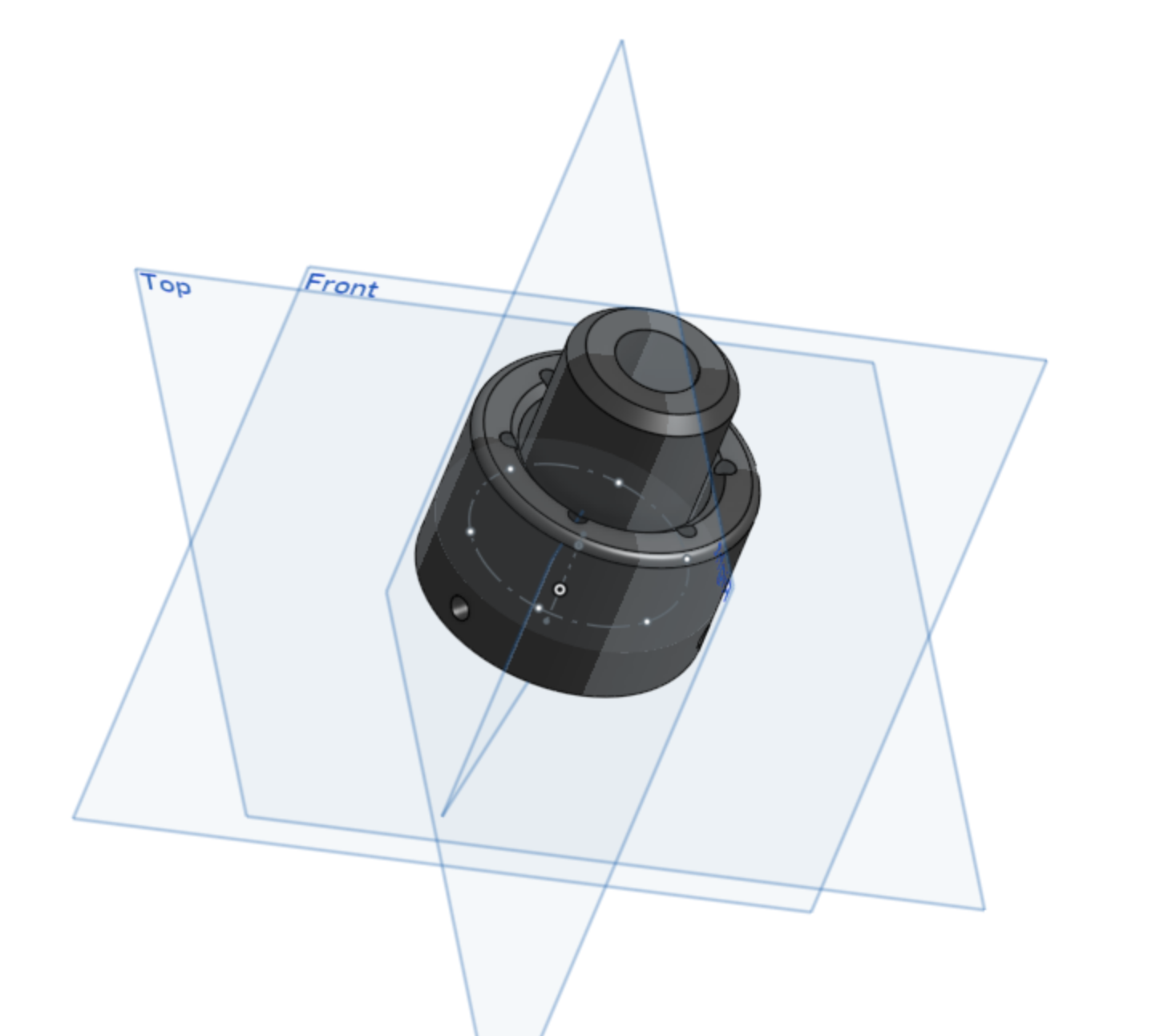
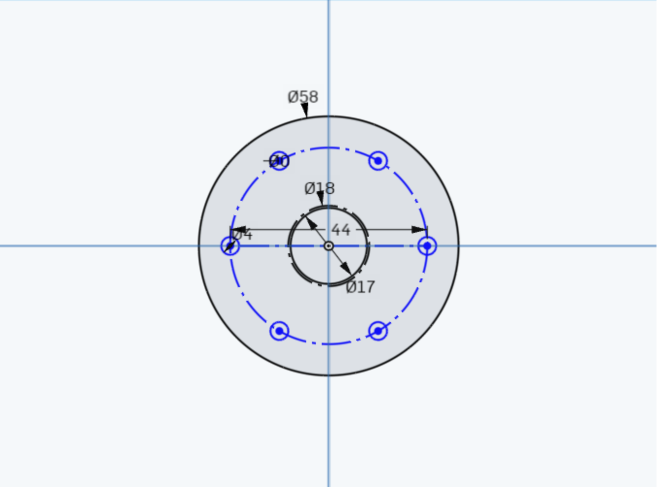
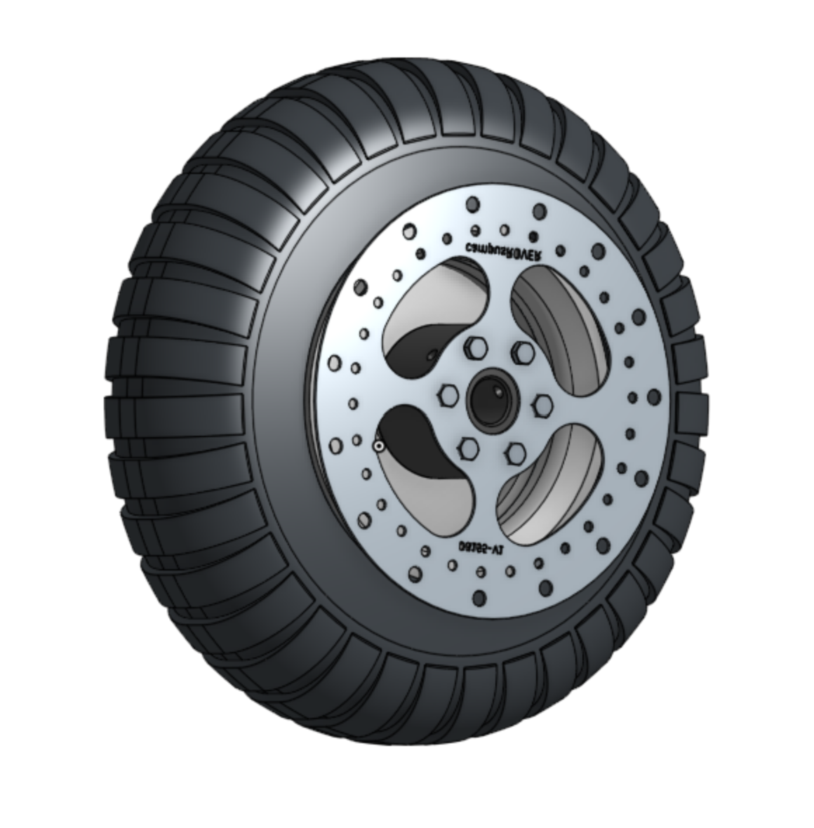
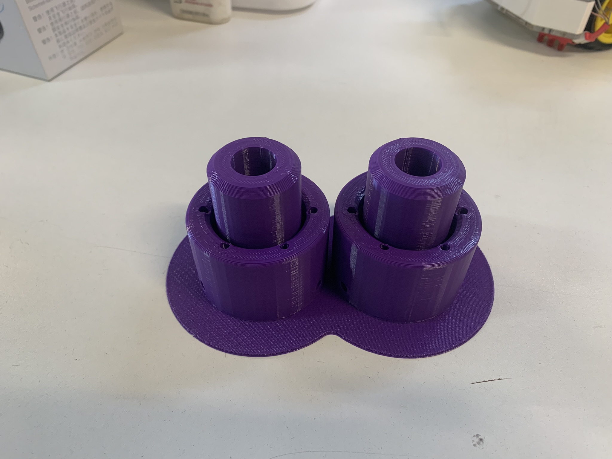
At first it doesn´t look like much, but this piece is designed to adapt a 10" wheel down into a 5/8" steel axis, allowing as well, the mounting of a disk brake for the scooter im making for my final proyect. This piece needs a deep cut between its exterior and interior sections, so it probably would be difficult to manufacture it subctractively. The part is shown in context in the following assembly, with the brake disk mounted and unmounted:

As the printed piece will be subjected to high torsional stress in all directions, the printed infill should be configured with a higher density and a geometry that allows for that kind of stress. Based on this, I chose a 60% infill density and a cubic geometry to allow for stress in every direction. As there are two wheels on the back of the scooter, I need two of these adapters.
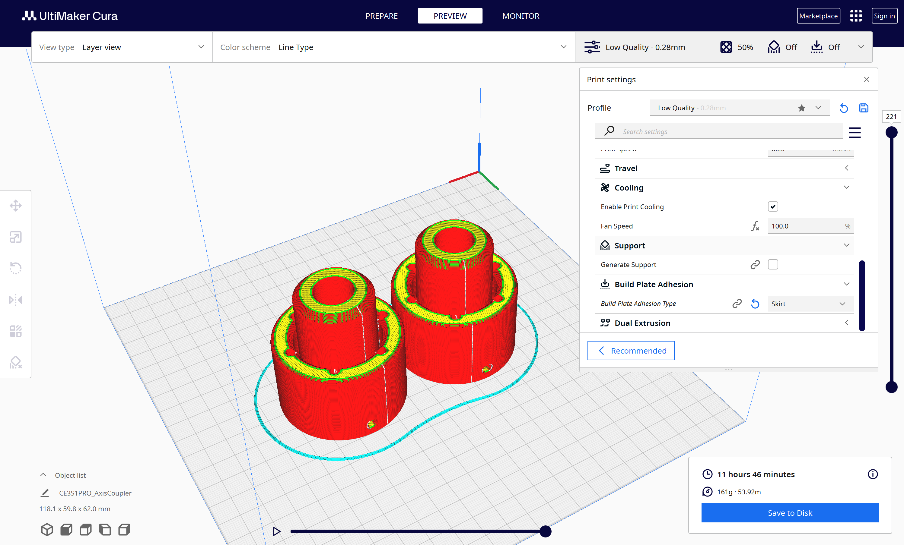
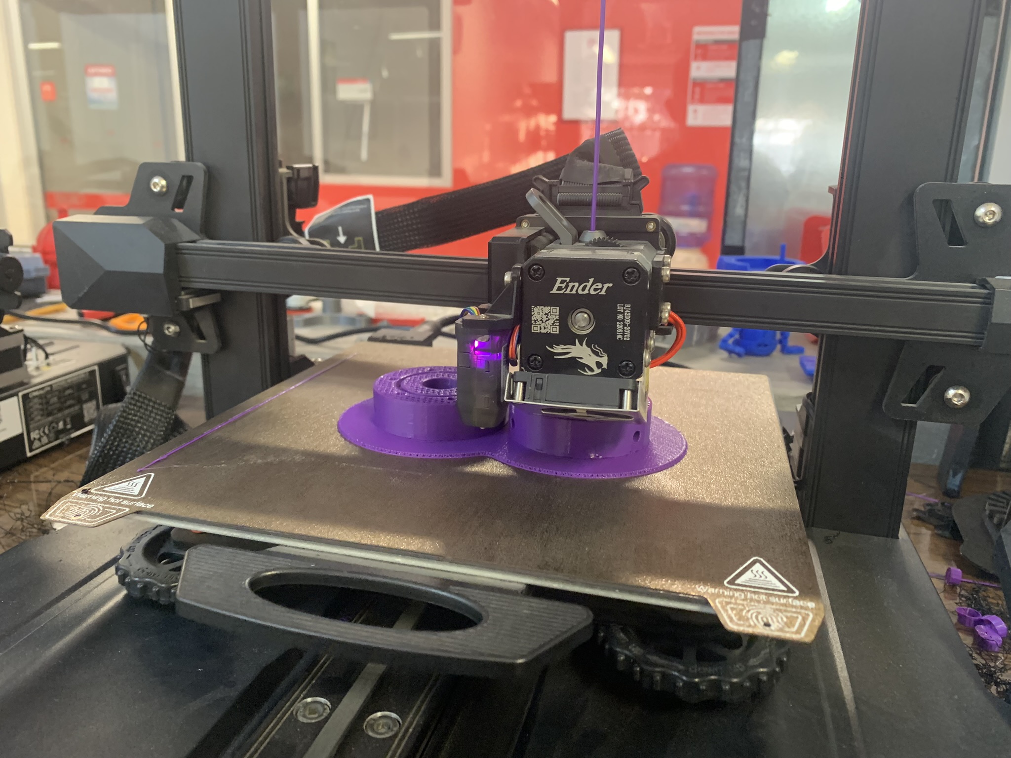
So, after twelve long hours on the 3D printer, I finally had my two pieces ready!
Thank you for taking a look into my 5th week's progress!