
3. Computer Controlled Cutting
This week, I had the opportunity to transform digital designs into tangible objects using two fascinating technologies: laser cutting and vinyl cutting. The former employs a focused beam of light to achieve precise cuts in both soft and hard materials by vaporizing the material beneath it as it moves. Conversely, vinyl cutting utilizes a very small blade that hovers above the material and applies pressure to cut through it. In both instances, the outcome is a 2D design precisely cut from the chosen material.
Let's do some Vinyl Cutting!
Remember the previously designed "campusROVER" logo? Well, I want to put it in full color on a white t-shirt using textile vinyl, a type of vinyl film that is adequate to be pressed against all kinds of textiles using a heated press.
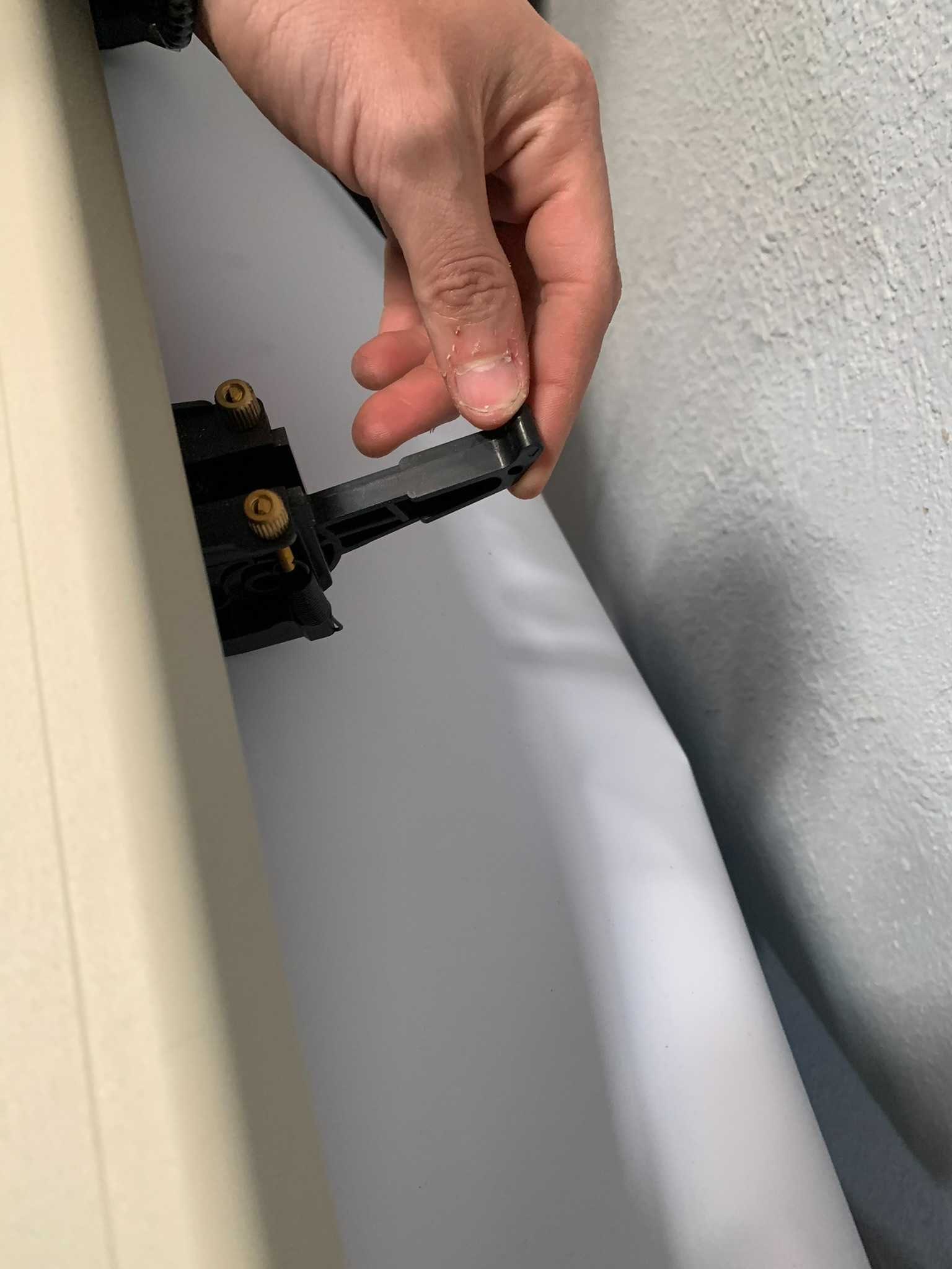
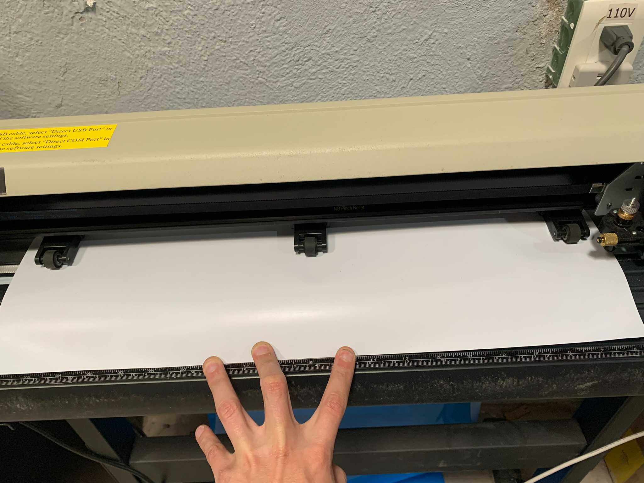
First we have to place our vinyl material on the cutter, we lift the levers found at the back of the machine, which hold still the material by pressing on it with rubber wheels. Then we insert the vinyl (with the shiny side facing down) and align it with the guide below.
When using the vinyl cutter there's two parameters of importance, Speed and Pressure, which are basically tell the machine how fast and how hard to cut the material, in this case, as textile vinyl is a bit thicker than regular vinyl film, I used a slightly more aggresive approach to cut the material: 280mm/s and 100g of force.
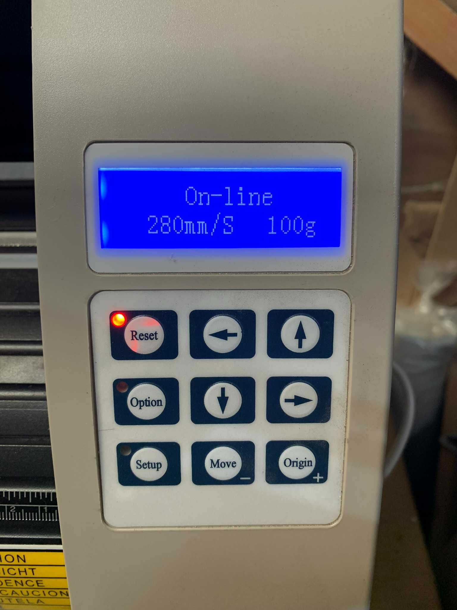
To move the cutting head, and define a starting point, we use the "Option" button combined with the arrows on the control panel, once moved to the position we want, we press the "Origin" button. The cutting head will drop and go back up again, indicating the origin is set.
Once this is done, let's go to the computer to prepare the cutting pattern.
Using the SignMaster software we can import any image or vector file in order to trace it and send it to the cutter. To do this we first import the file we want to cut using the menu FILE -> Import. The imported image will show on the blank canvas.
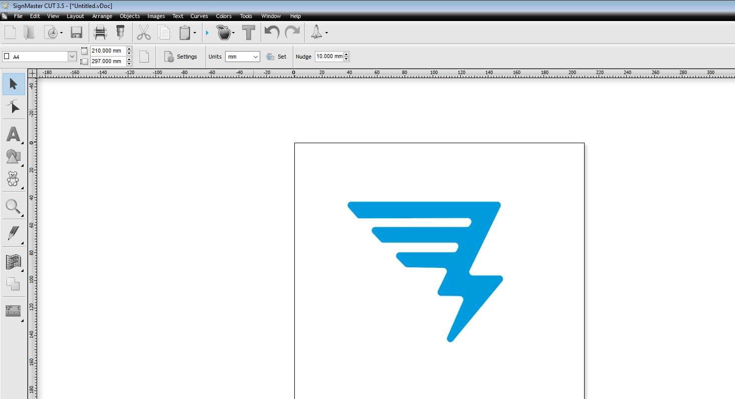
As you can see, I only placed the blue icon part of the logo, this is because when using the vinyl cutter, you have to do different cuts for every color in your final design, as you have to change the actual material being cutted. In this case I started with the light blue vinyl, in order to cut this part of my logo.
To trace the image in order to cut it, we press the "Trace Image" (apple shaped) button, a window will open showing us the expected output, if we are satisfied with it, which I was, then just click on "Trace".
A contour will be generated upon the image, so we can now delete the image below it, leaving us with just this:
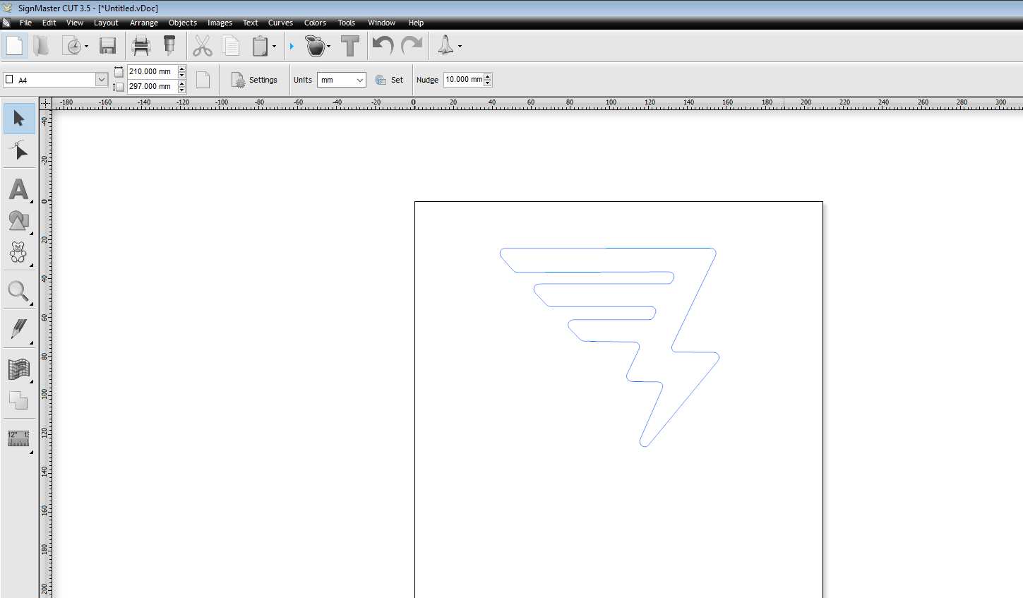
We can now freely re-size the contour according to our needs, by selecting it and modifying the dimension boxes on the top left corner. In my case I opted for a 40mm x 44mm shape. As the cutting is happening on the opposite side of the vinyl we need to horizontally mirror the image so it appears straight once we place it on the t-shirt. To do this, we right-click on the image trace, and click Transform -> Mirror -> Horizontal Mirror.
Once resized, mirrored and properly placed on the uppermost right corner of the canvas, we can proceed with the cutting.
Click on the "Send to Cut" button (Blade shaped icon) and a window will open:
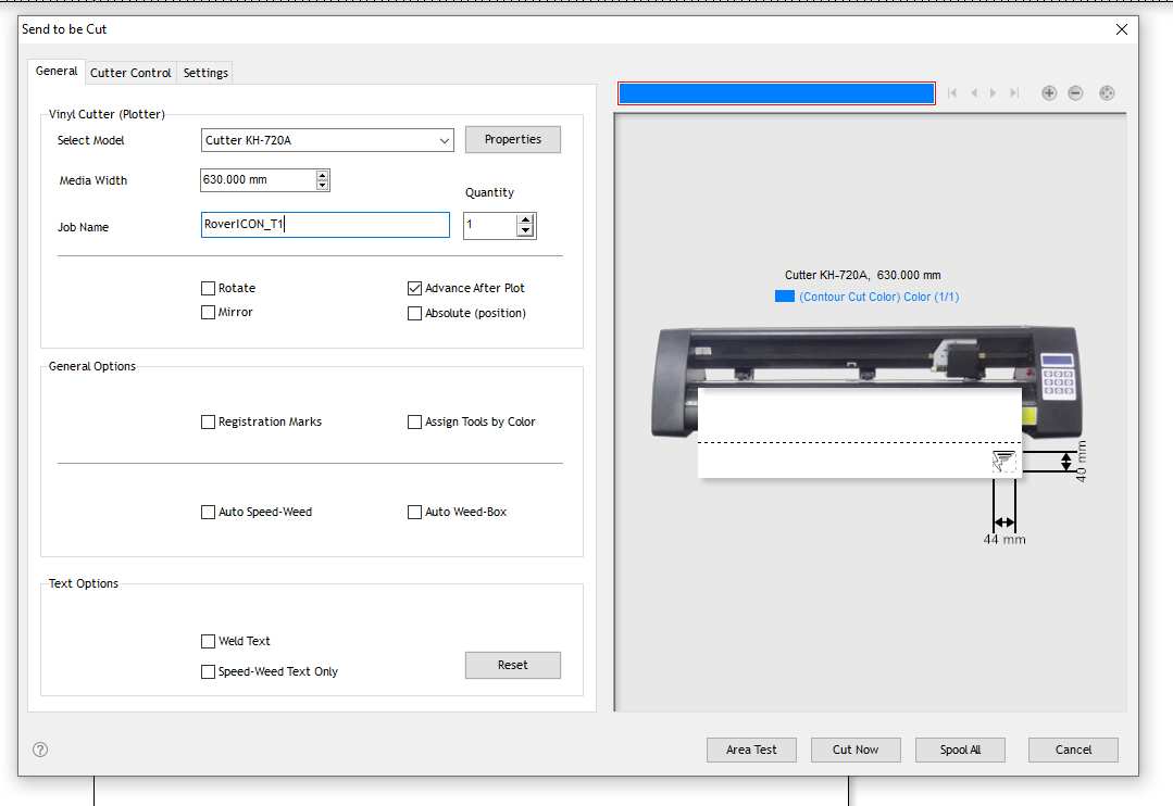
Once here, it's important to confirm the connection with the machine and that the proper "media width" parameter is correct, this refers to the available width of the material we place on the cutter.
If everything seems right, we click on "Cut Now" and the cutting process will start inmediatly.
Once the vinyl is cutted, we need to remove all of the vinyl that does not form part of the design, leaving behind only the shape of the icon that we want:
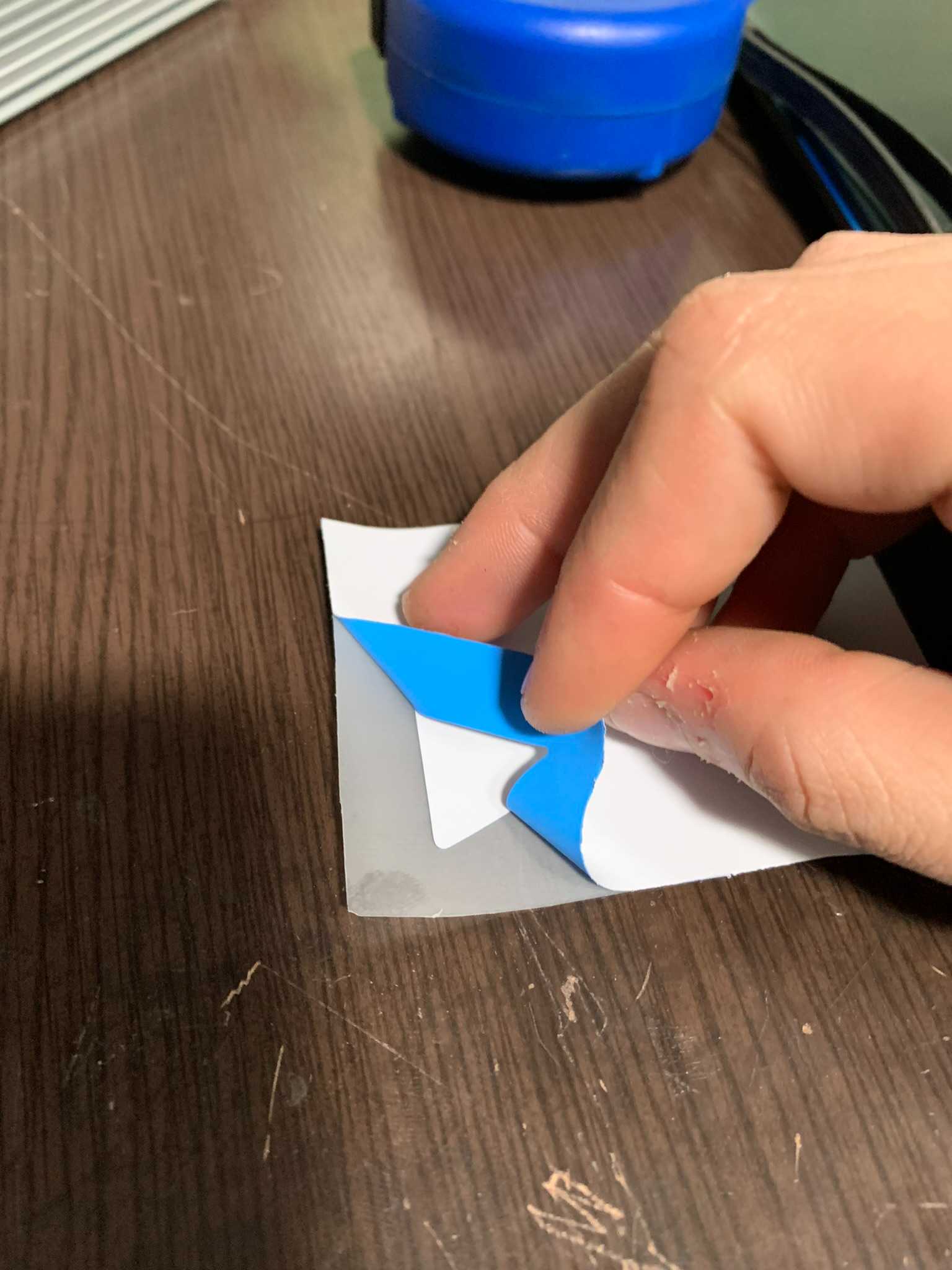
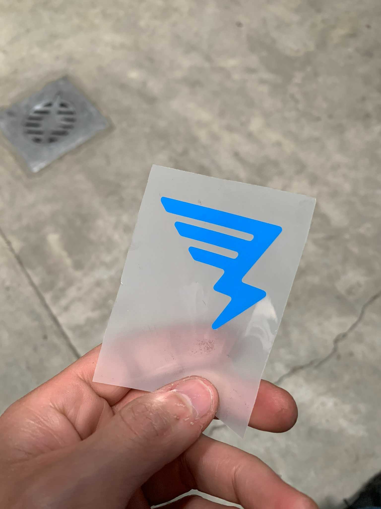
The thicker plastic film serves as a placeholder for the vinyl until we press it onto the textile, that's why we had to mirror the image, so when we press it, it stays the right way up.
Now, following the same steps than before, we proceed to cut the letters of the logo, in this case, changing the vinyl from the blue that we previously used to a black one. Then we peel off the vinyl we don't want, this time, there's also left-over vinyl inside the letters that we also have to remove. (I cutted the whole logo this time just because I wanted to also have an icon in black).
Now that we have both designs in the colors we need, it's time to press the design on the textile, but before I ruin my t-shirt I did a test-press on a spare piece of cloth. I configured the press to 200°C and the timer to 4 seconds using it's control panel. Then, I placed the piece of cloth on the press bed, then the vinyl cut with the thick plastic facing up, and using the handle gave it a squeeze. This was the result:
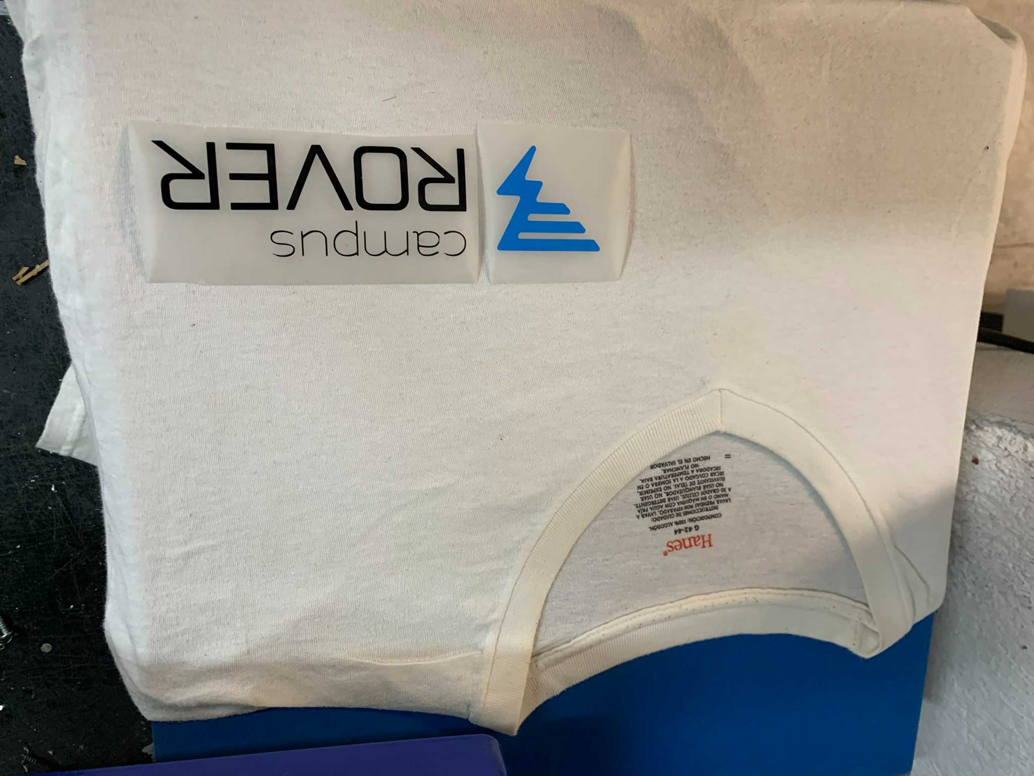
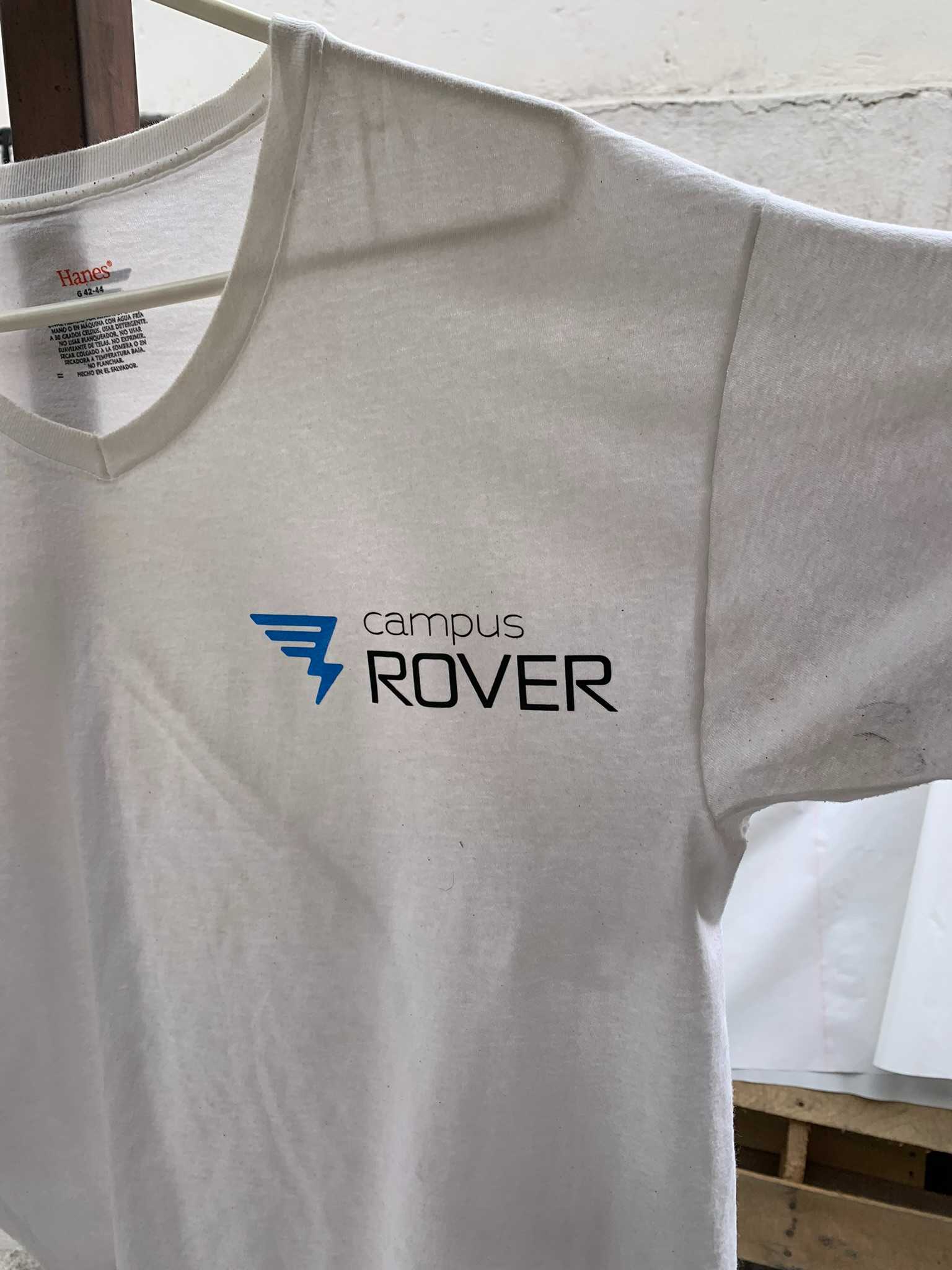
Satisfied with the result I proceeded with pressing the t-shirt, so, after arranging the blue icon and black letters within the space I wanted it to be on the t-shirt, I pressed it down with the exact same parameters. On the left you can see the arrangement before pressing, and on the right, the final result!
Making a Construction Set: Laser Cutting!
As previously mentioned, laser cutting is an incredibly powerful subtractive manufacturing method, capable of cutting materials with exceptional precision, regardless of whether they are soft or hard. In my case, I will be using a 100W CO2 laser cutter from CamFive, with a working area of 90cm by 60cm. Although this laser cutter is highly capable, it cannot cut many hard materials such as metal, stone, glass, or similar substances. Additionally, it is not particularly effective at cutting materials thicker than 12mm.
When laser cutting, there are two main parameters to consider in order to achieve the desired results: speed and power percentage. Speed, measured in millimeters per second (mm/s), refers to how fast the laser moves along its cutting path. Power percentage, on the other hand, denotes the amount of laser power (up to the machine's maximum capability) that is directed to the focal point on the cutting head. It's worth noting that the actual laser tube is located behind the machine, not on the cutting head itself. The laser beam is redirected towards the material being cut using mirrors. Exercise caution regarding the invisible laser beams along the X-axis, which run between the cutting head and the mirrors on the far left or right; exposure could result in burns.
Through its already known caracterization, I was able to define the correct parameters for the material I wanted to cut: You can cut 3mm MDF with this machine using 90% power and a speed of 25 mm/s.
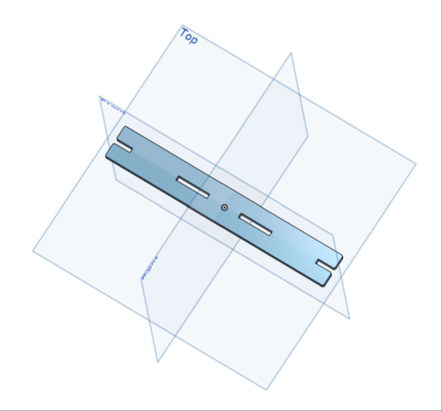
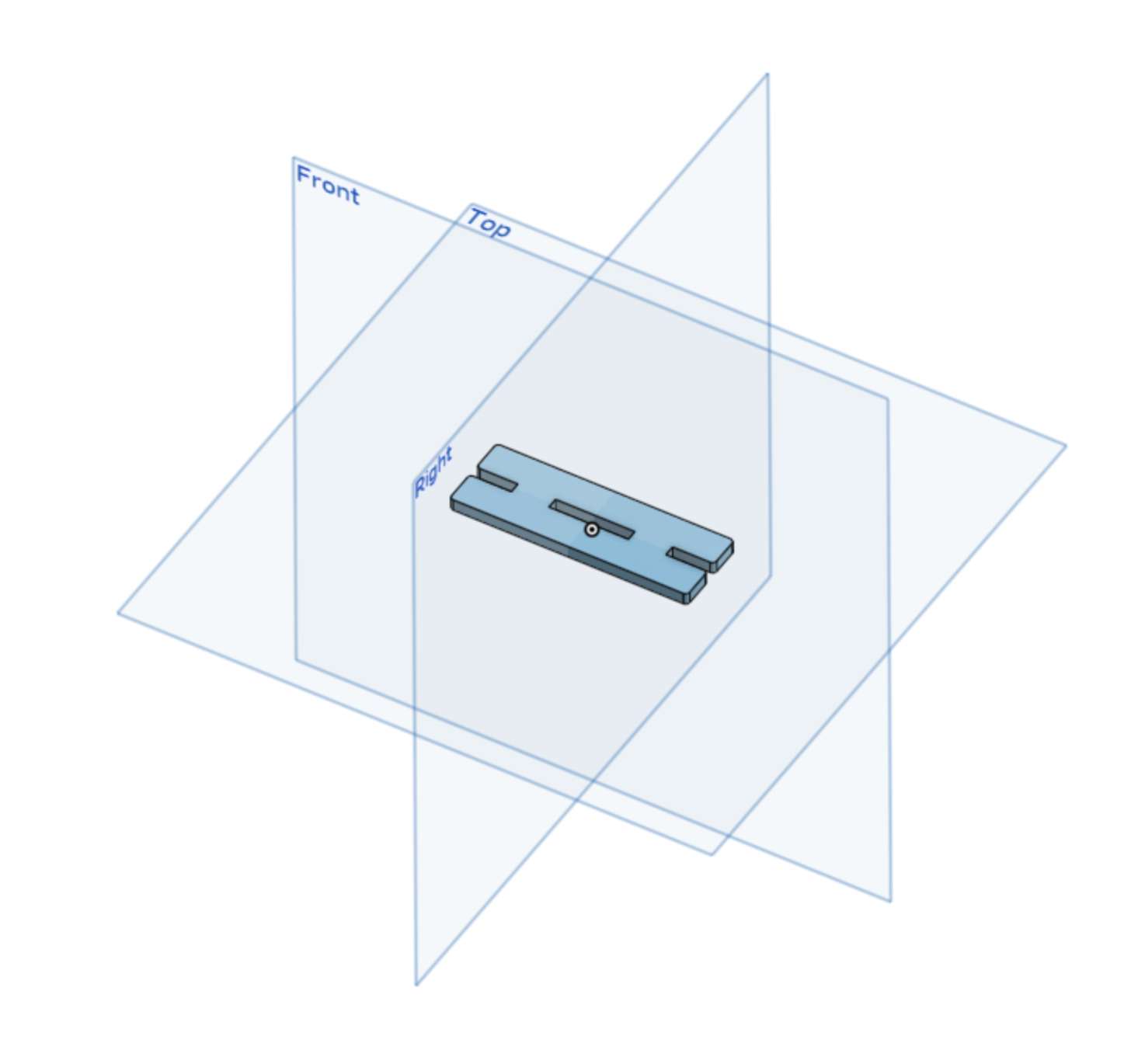
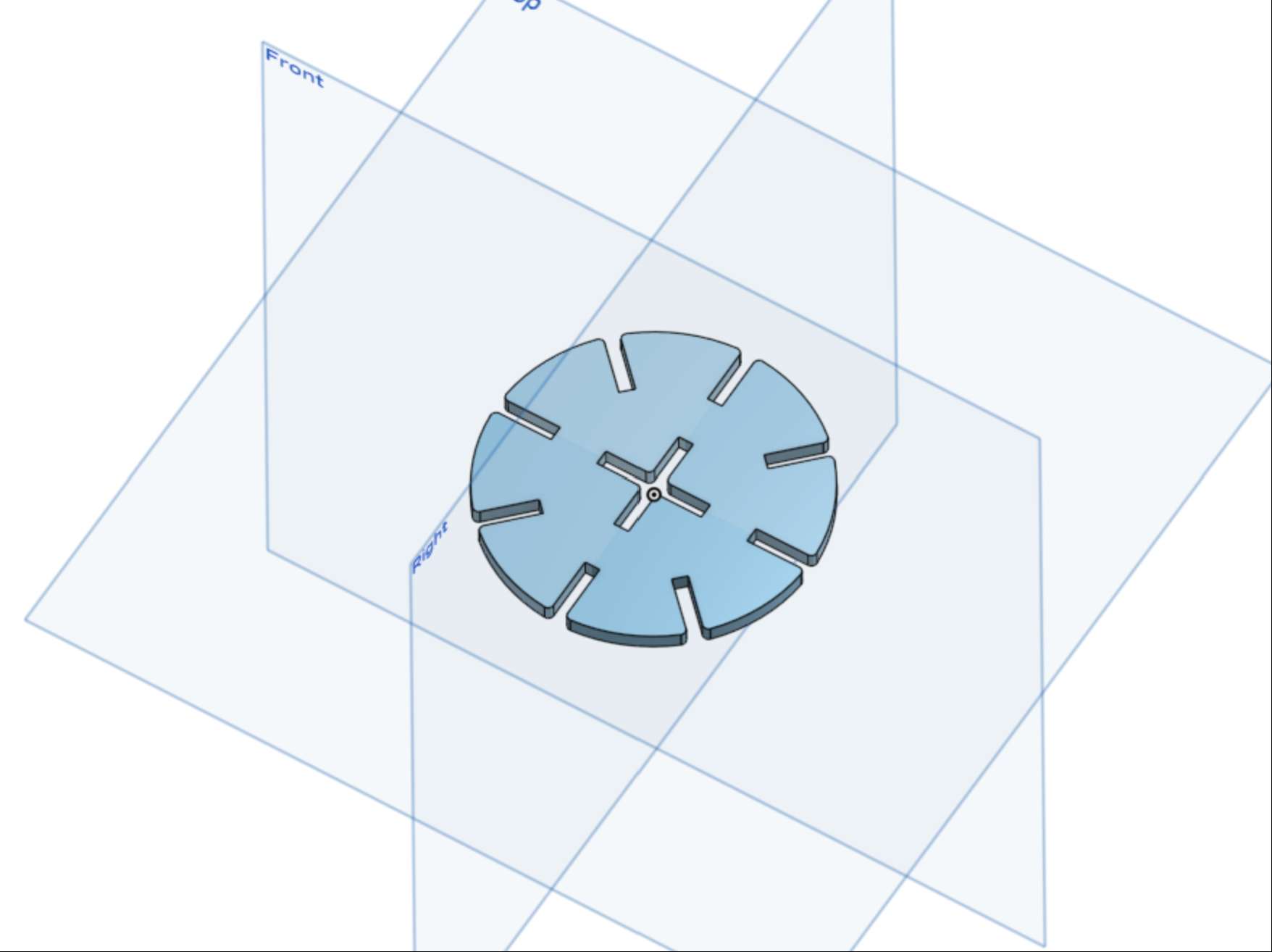
I previously designed the pieces for a construction set using OnShape, as shown on the past week's page:
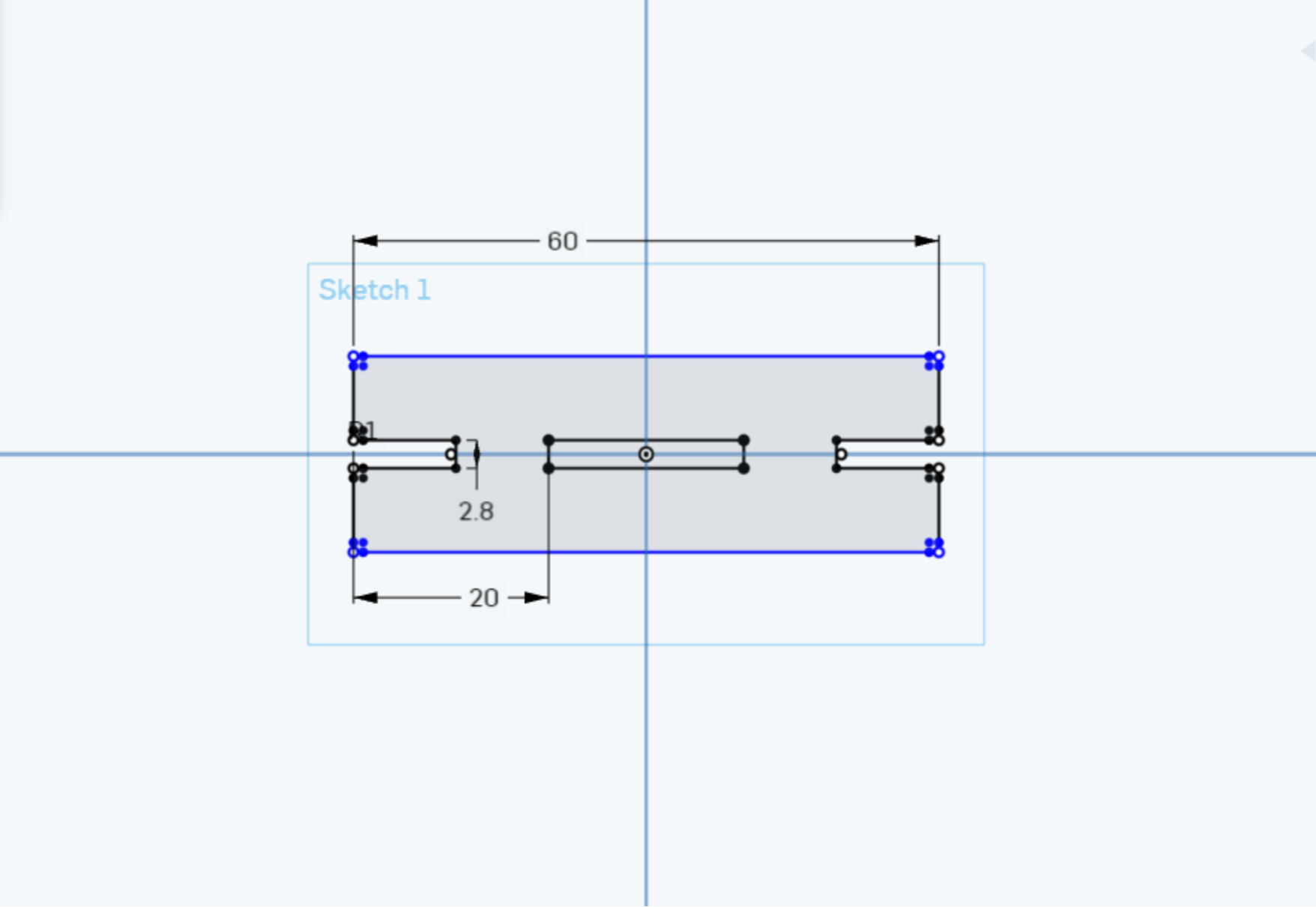
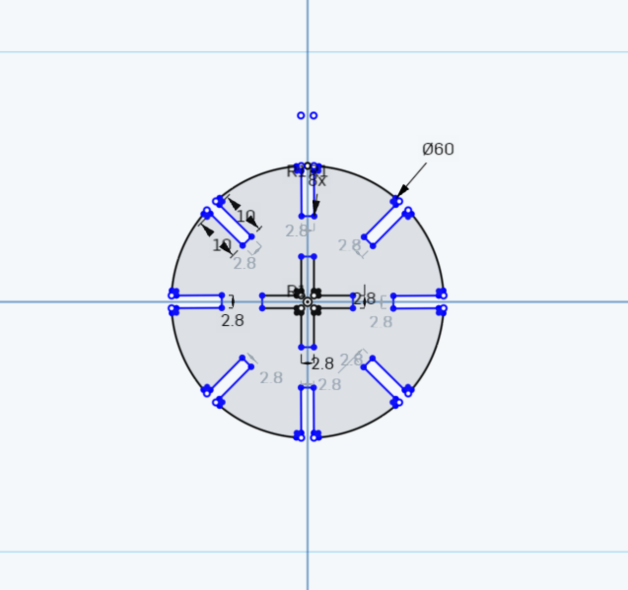
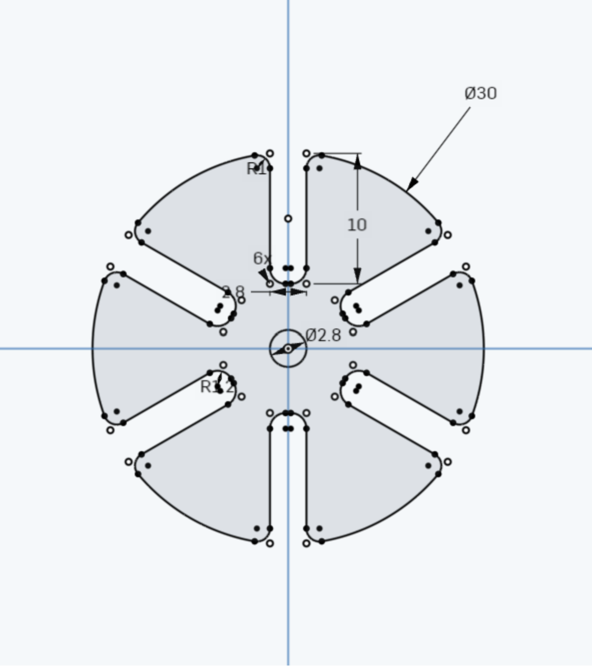
I then exported each design from OnShape as a .dxf file, an essential file extension when laser cutting.
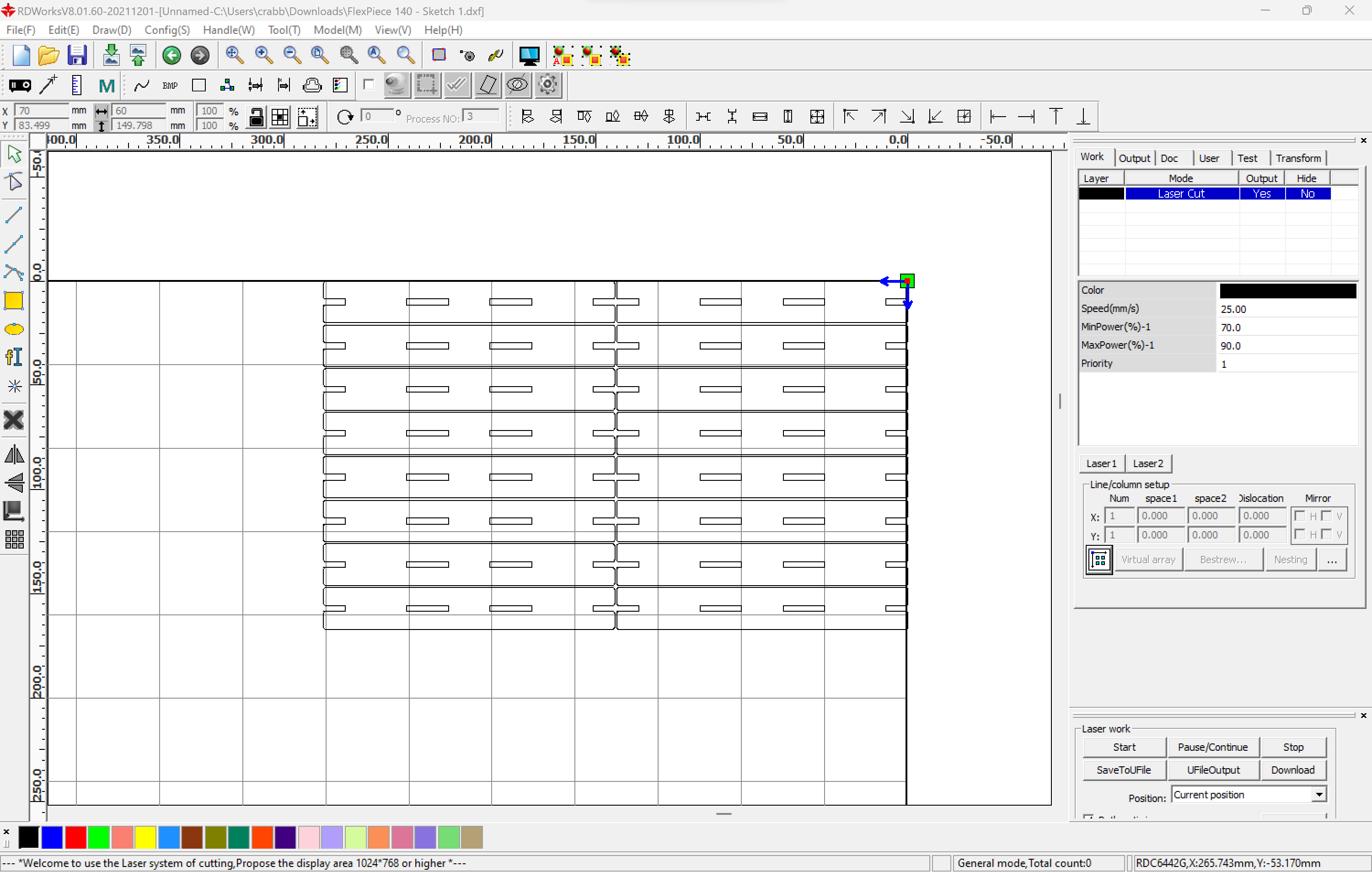
Then, I imported all the .dxf files into RDWorks, the laser cutter's included software. In the following image I placed every file at the same time for illustrative purposes, but this is not ideal, as it wastes a lot of material by allowing large spaces between figures.
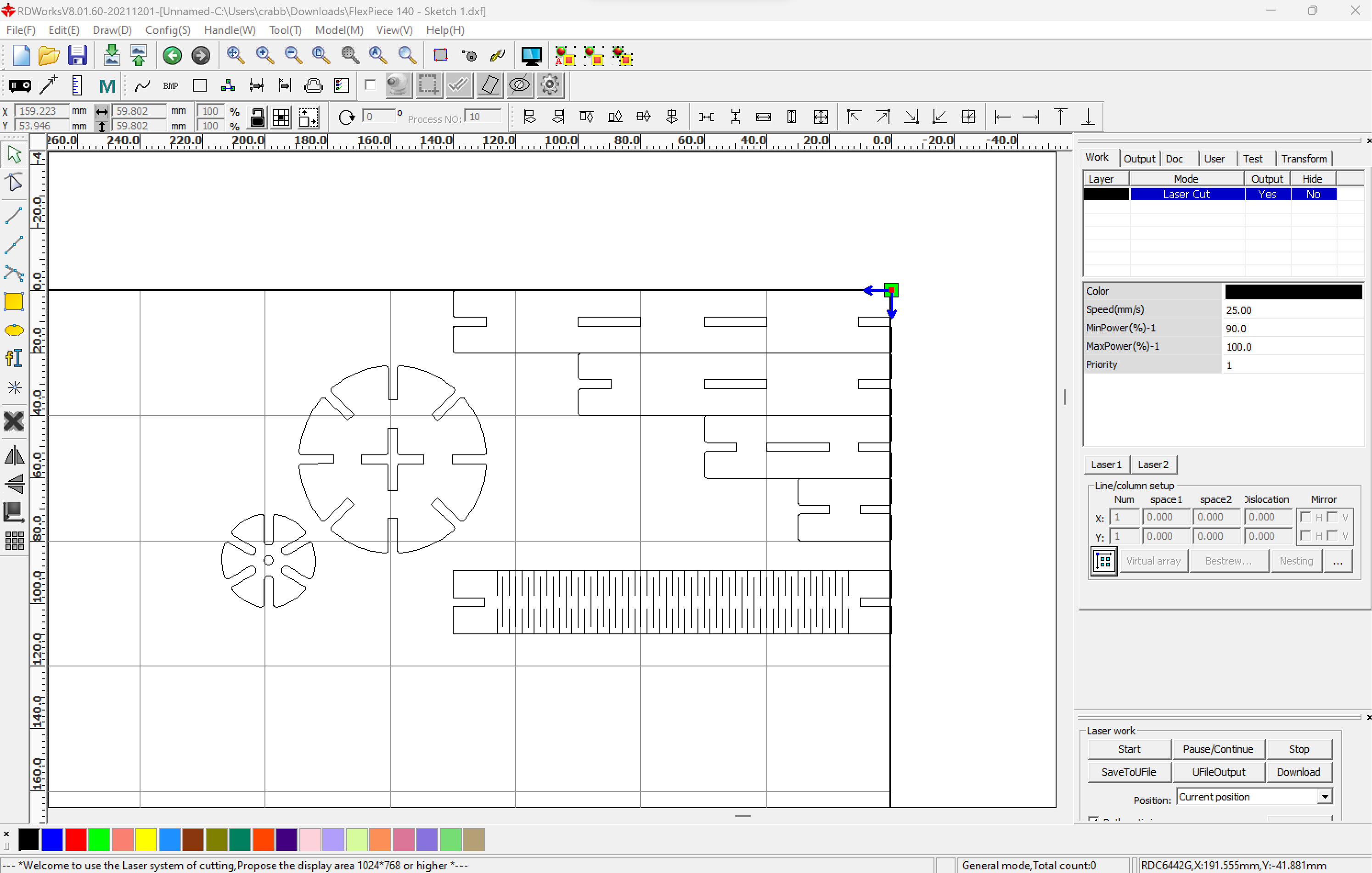
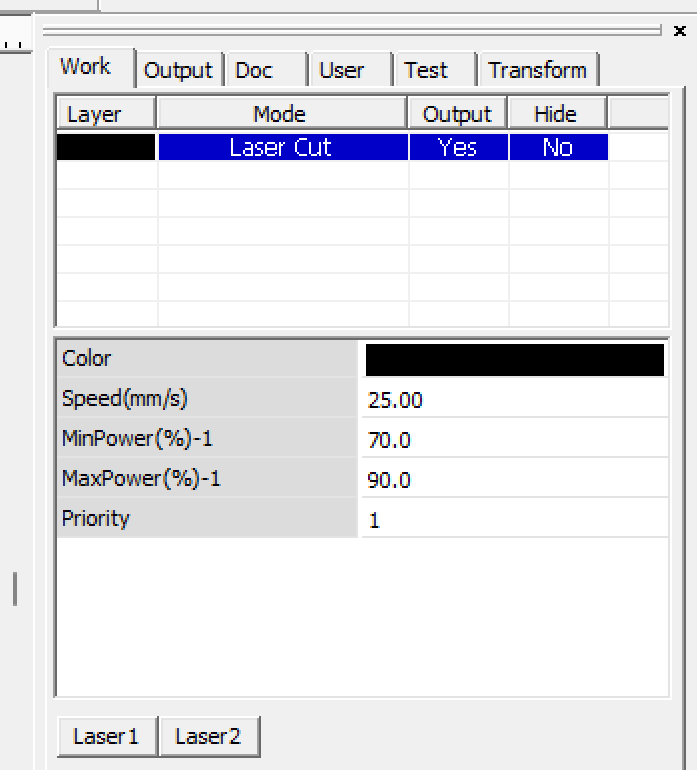
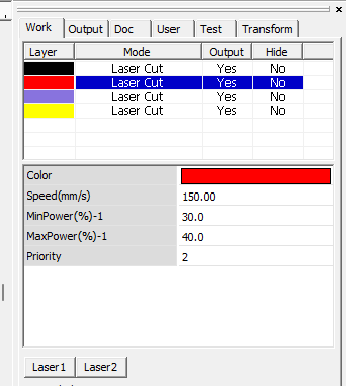
Now, I have to configure the cutting layer parameters for the 3mm MDF I wanted to cut, so let's do that using the right-side panel. If needed (in this case is not) we can create different colored layers in order to use different parameters on the same file, to, for example, cut and engrave MDF on a single batch (multiple layers shown on the left).
Now, let's make an actual cutting arrangement, in order to optimize the usage of the material. Clumping together similar shapes is useful to avoid creating empty spaces! So, if I want many pieces of one design, I simply duplicate them and place them next to each other, but leaving a small gap between them, so the cutting paths don't overlap, as that may cause double passes on the same spot, burning the material on those areas.
Now that the file is ready, lets prepare the machine for cutting!
Of course, turn on the machine, in my case I do that by flipping up this red switch on the right side of the cabinet. Once the machine has finished its inital calibration, we can move the cutting head wherever we want by using the arrows on the control panel. Once you have decided on a starting position (just like in the vinyl cutter) you can press the "Origin" button in order to set those coordinates as the starting point for whatever you want to cut.


We now have to check if the cutting head is 5mm above the material, if that is not the case, we need to calibrate it by placing an object between the head and the material which measures 5mm. You can use a USB Type-A male connector, a specially made spacer, or in my case, a 5mm metric wrench. By turning this golden knob, we can loose the cutting head assembly to change its height and calibrate it using our 5mm object.


Now, close the machine's lid so we are ready to cut the piece arrangement, which will result in 16 individual pieces. By clicking the "Start" button on the lower-right corner, the file is automatically sent to the machine for cutting.
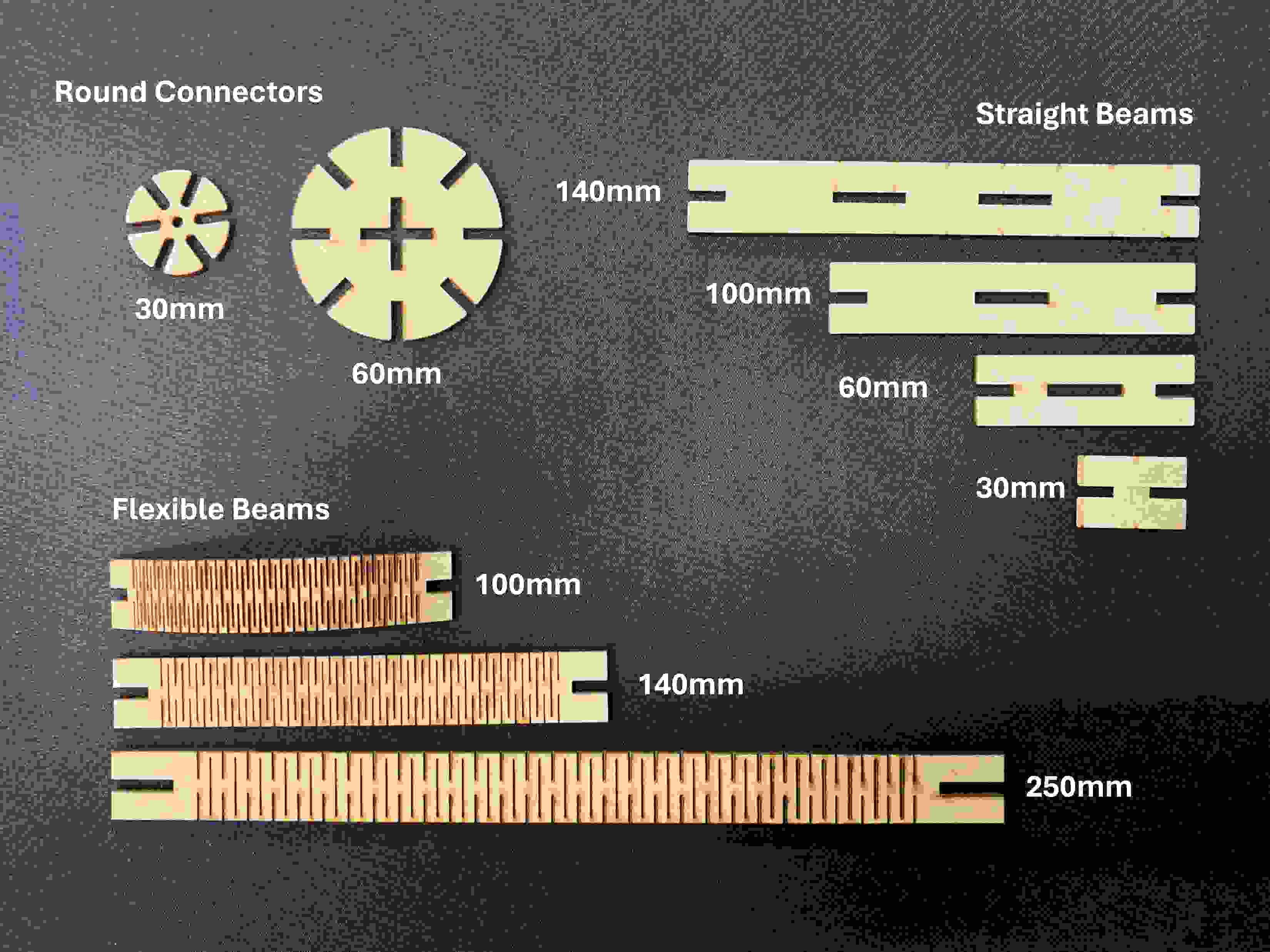
Once the cutting is finished, we can lift up the lid and take out our finished pieces. Following this process I made the following pieces for my construction set:
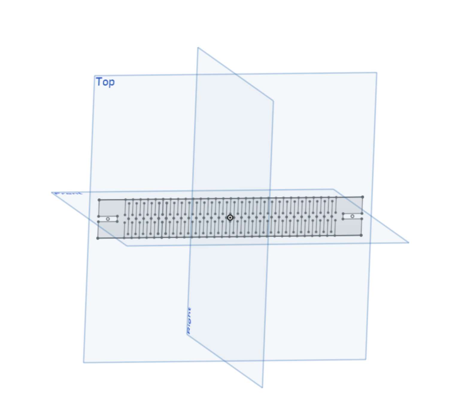
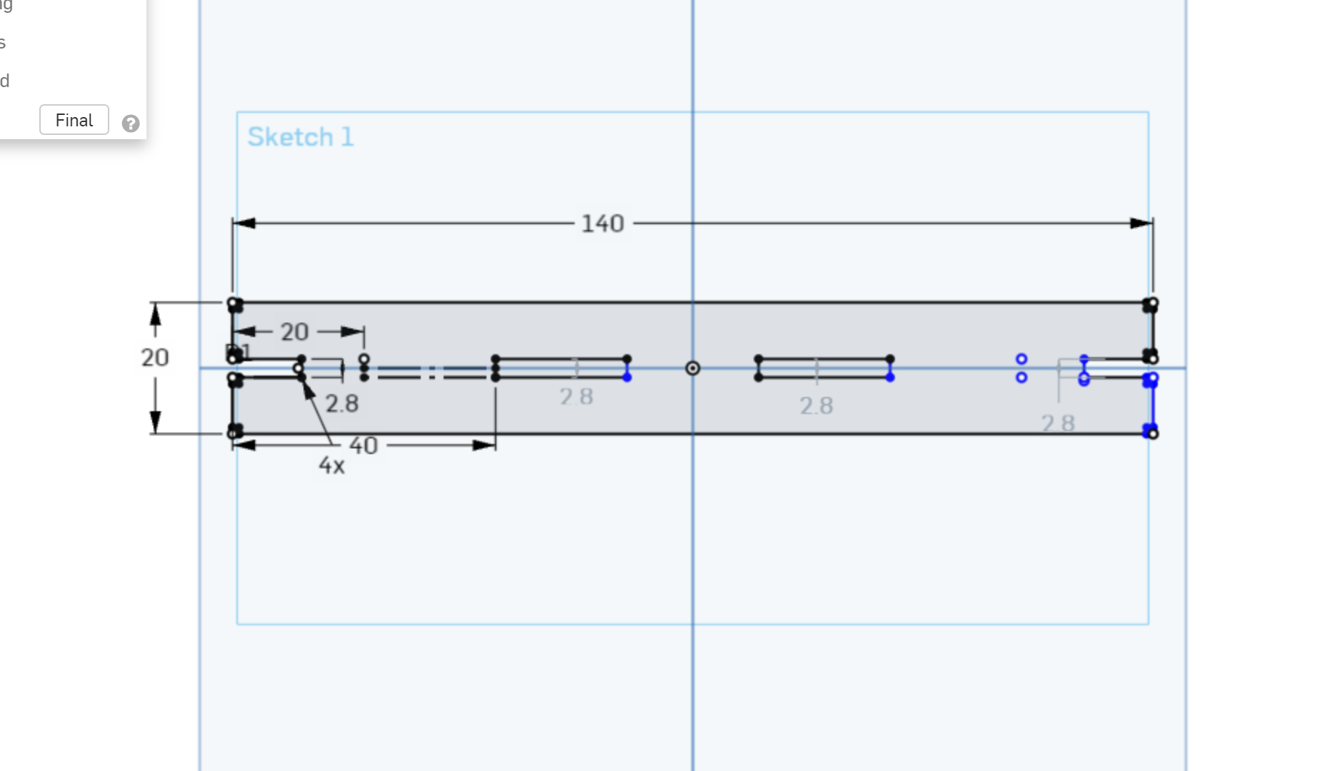
I chose to design a press-fit approach for the construction set because of its simplicity and durability. When designing in OnShape I accounted for a 0.2mm Kerf in my tolerances, making the joints between pieces quite strong, but easy to use at the same time. I even had the chance to test "living-hinges" adding another dimension of flexibility to my construction set.
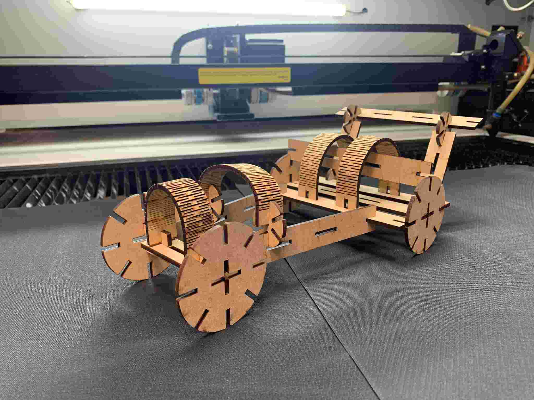
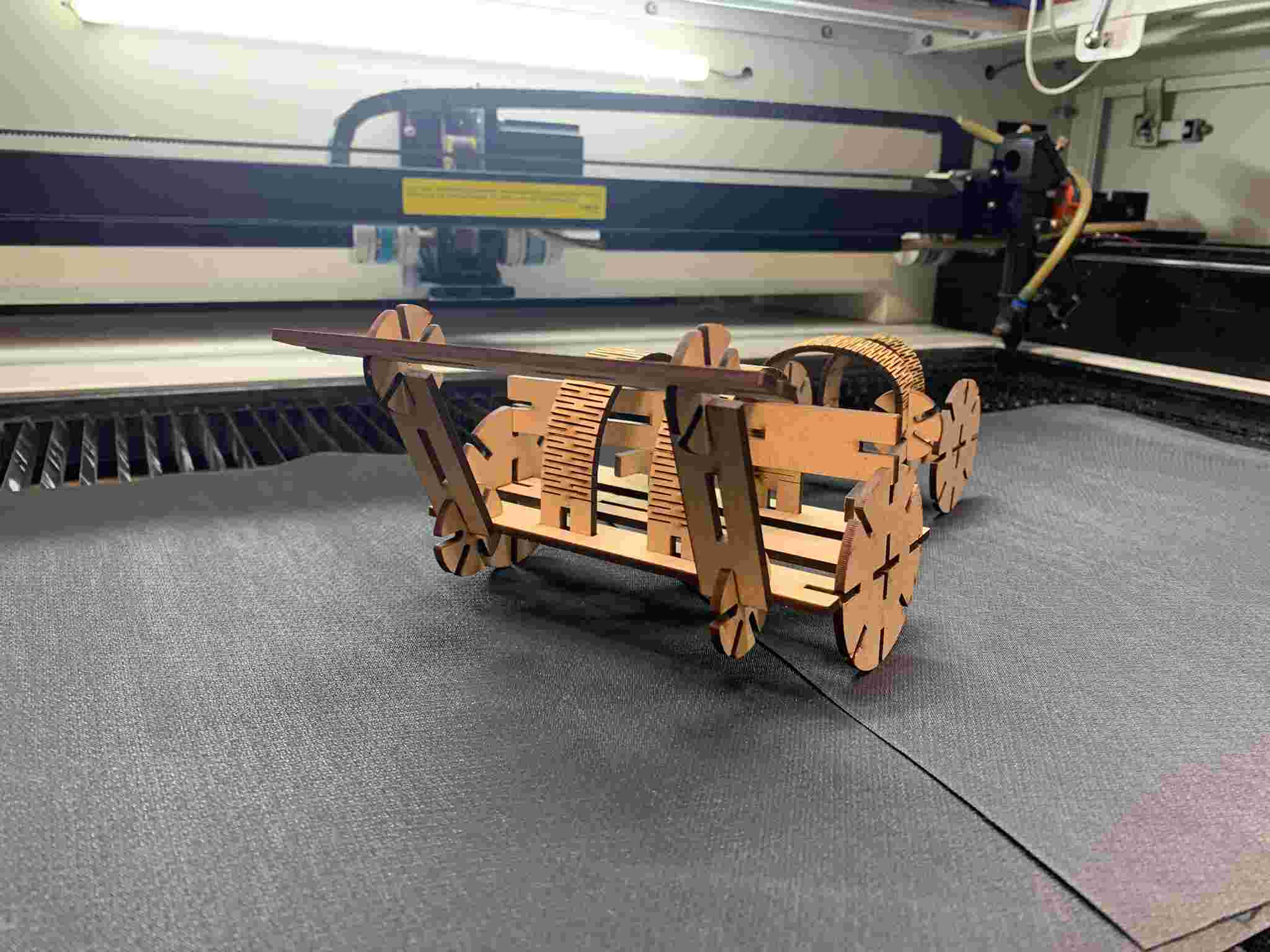
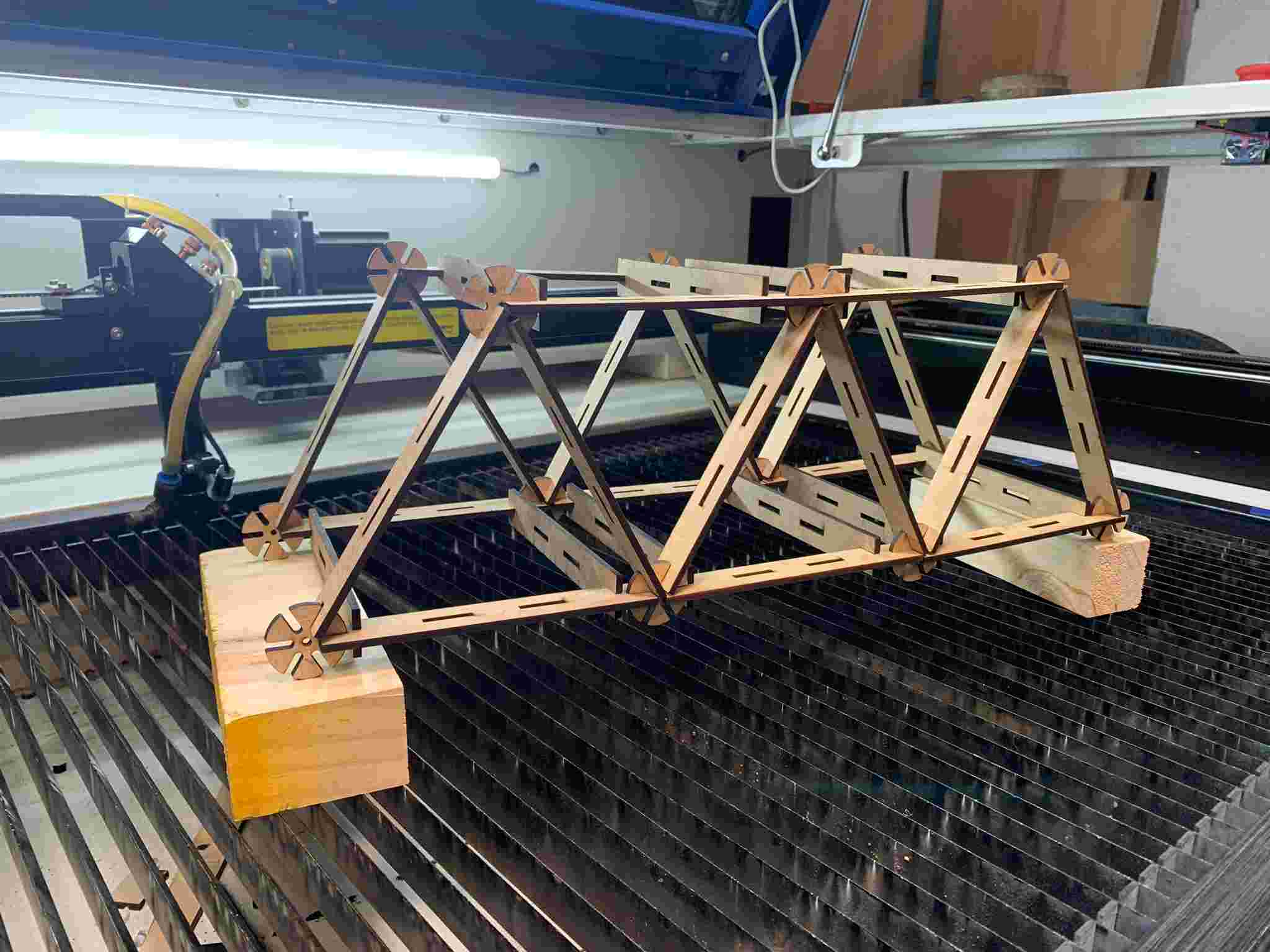
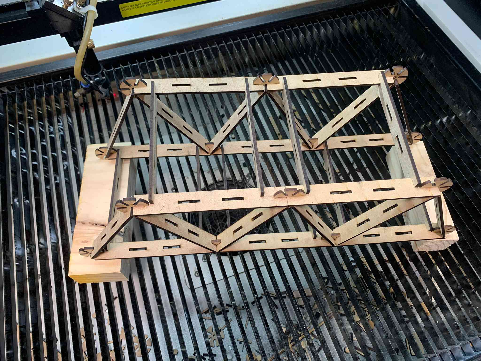
All the pieces within the set fit into each other, beams can be fitted between them using the exterior or inner slits, round connectors add the possibility of angles to the assemblies, while the flexible beams give texture, bouncyness and roundness to whatever you may build with it. Using those pieces, I devised two assemblies(what I could call a race car and a bridge) which I show on the following images:
Thank you for taking a look into my 3rd week's progress!