
2. Computer Aided Design (CAD)
This week I worked on getting used to the CAD tools I will use for the rest of the FAB Academy, in order to bring into reality my final proyect.
FAB Academy offers 3 CAD software licenses, and we're supposed to stick with one of them for the rest of the course. So let's dive into two of them, the ones I found could be the most useful to me.
In the case of the 2D drawing software, I chose Adobe Illustrator, just because it is the most popular and most documented, 2D design software out there, and I already own a license for it.
Let's Illustrate!
I want to design another logo for the "campusROVER" final proyect, as the previously made logo never convinced me that much.
As I am no graphic designer, and creativity is sometimes limited, I decided to take advantage of modern AI and asked ChatGPT for inspiration. With the following prompt, GPT gave me the below shown image: "I am designing a logo for an electric scooter brand. I need it to be minimalist, but that at the same time it shows movement, technology and simplicity. Could you generate an image for me to get some inspiration?"

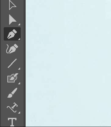
As you can see, it generated something interesting, but Im not talking about the whole image, but of the icon on top of the scooter, I thought it could serve as a really cool logo with some personal intervention. So I just cropped the image from a screenshot, and pasted it on a blank Illustrator document with the intention of recreating it using the pen tool. On the right-hand image you can see the result.

To finish, I just colored the icon in light blue, and added my branding using the fonts "Adrianna Extended" for the upper text, and "ZektonRg - Regular" for the one in the bottom.

I then created the horizontal variant for the logo, using the same fonts and icon but a different disposition:

Now, I will do this exact same process using Inkscape instead of Illustrator, which opposed from the Adobe product, Inkscape is free.
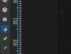
I started exactly the same with the intention of tracing the AI generated logo. Using Inkskape's pen tool I traced the image, which inmediately turned black after the tracing was finished.

After this, I deleted the background and painted the black silouhette in light blue using the paint bucket tool:


Now, using the text tool I placed some unformatted text next to the logo:


I then looked for the specific fonts I used in the design made in Illustrator, and applied that format and arrangement:

As you can see, the workflows in both software offerings are very similar, and although Inkscape is free to use, I think I'll stick with Illustrator just because I already have a license for it and I am more familiar with it.
CAD Design: SolidWorks Or OnShape?
SolidWorks is a very powerful CAD software, and in many places an industry standard, I have already experience using this software, which makes it easier for me to dive into this week's tasks.
Let's make a simple mechanical piece using SolidWorks 2024:
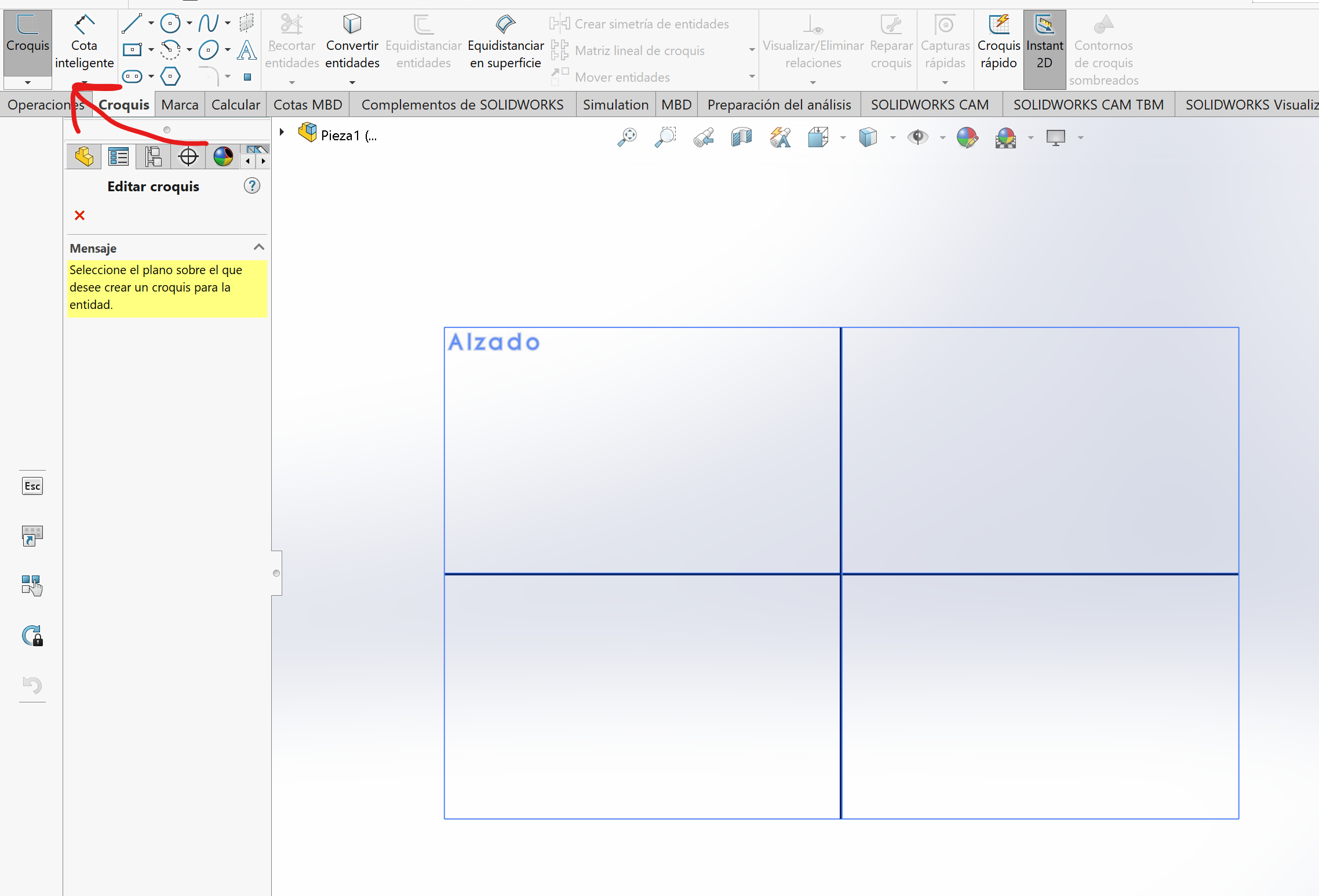
To start we create a Sketch and select a plane, in my case SolidWorks is set in Spanish, but the button arrangement is the same.
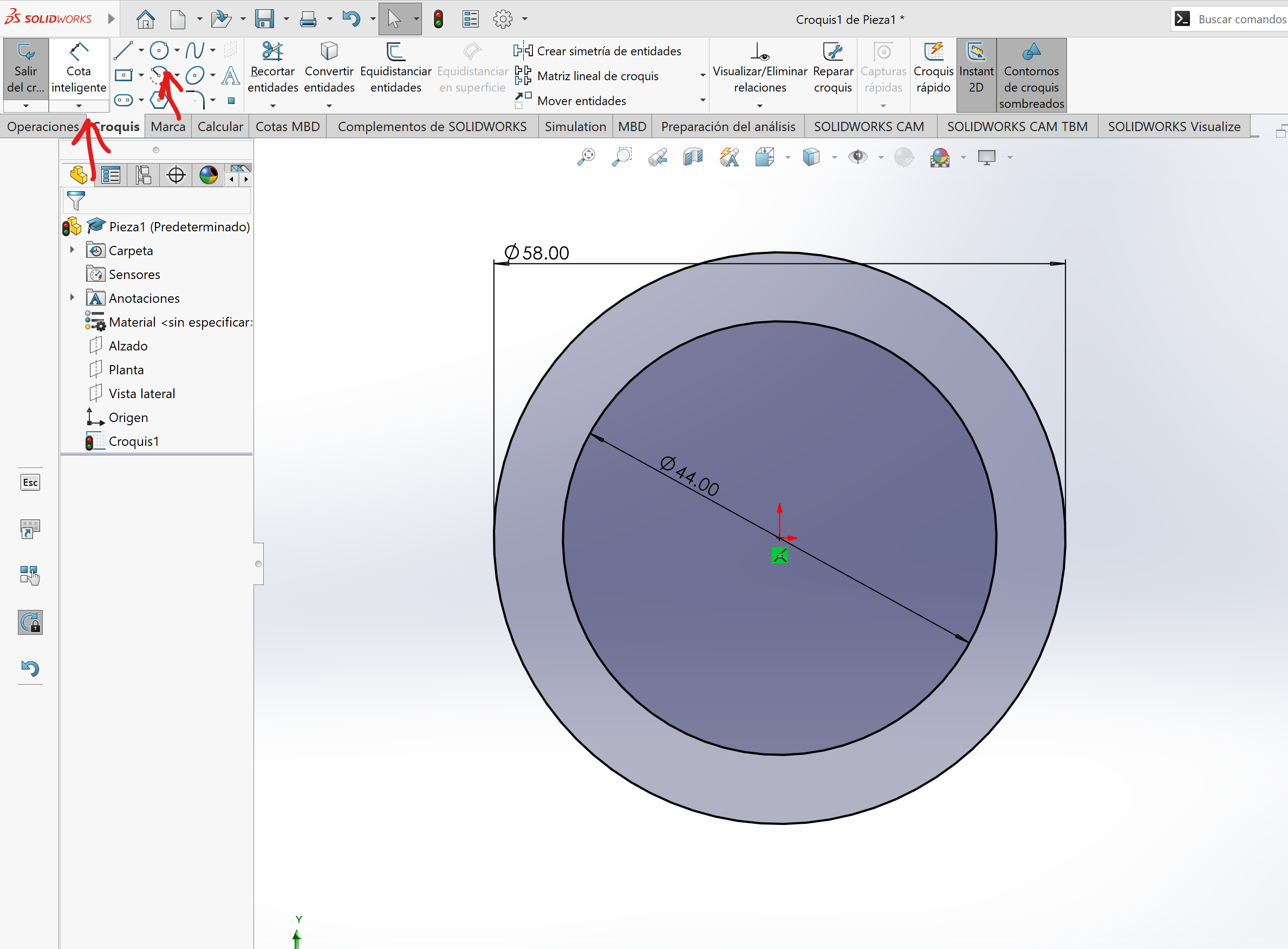
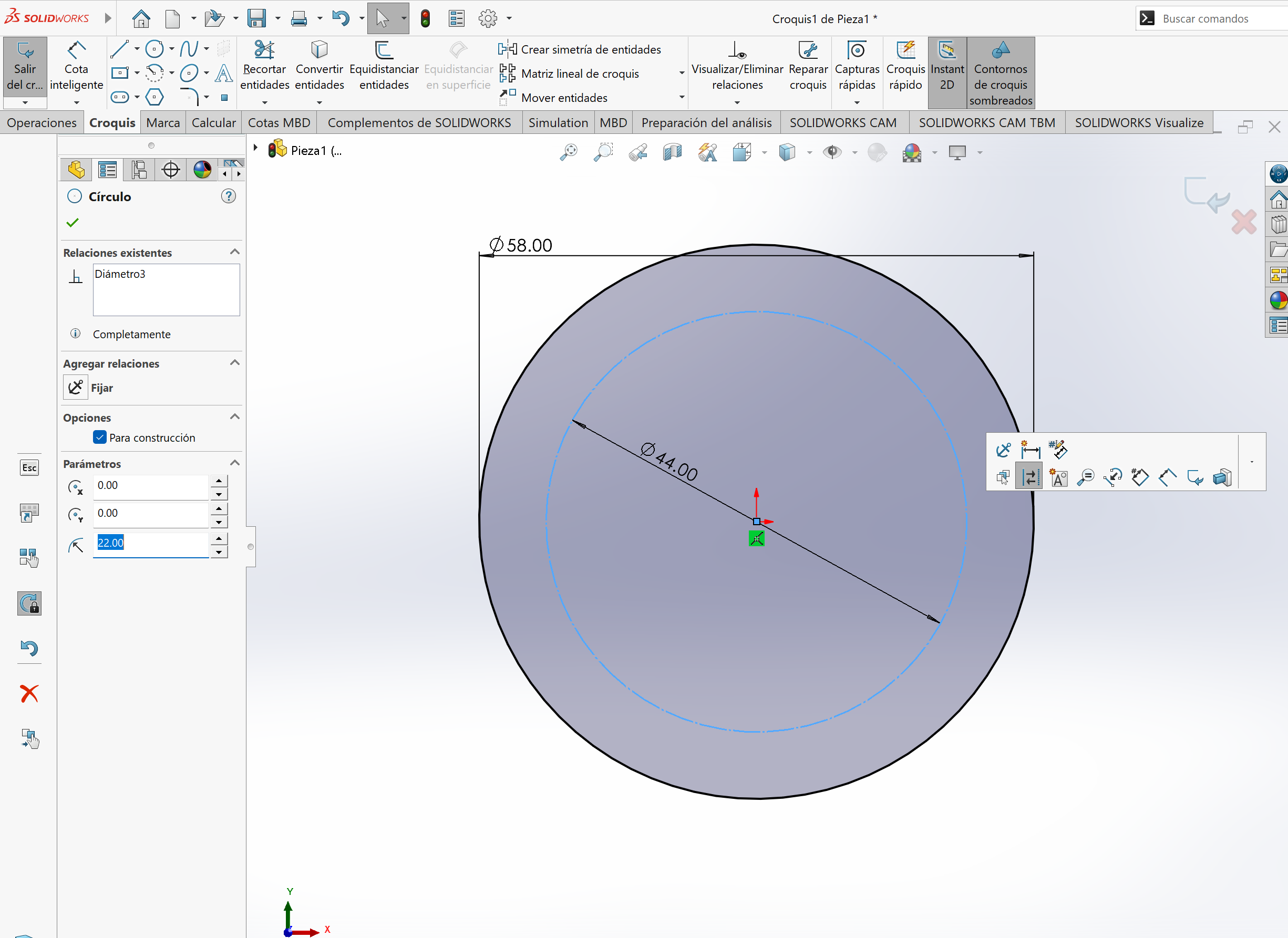
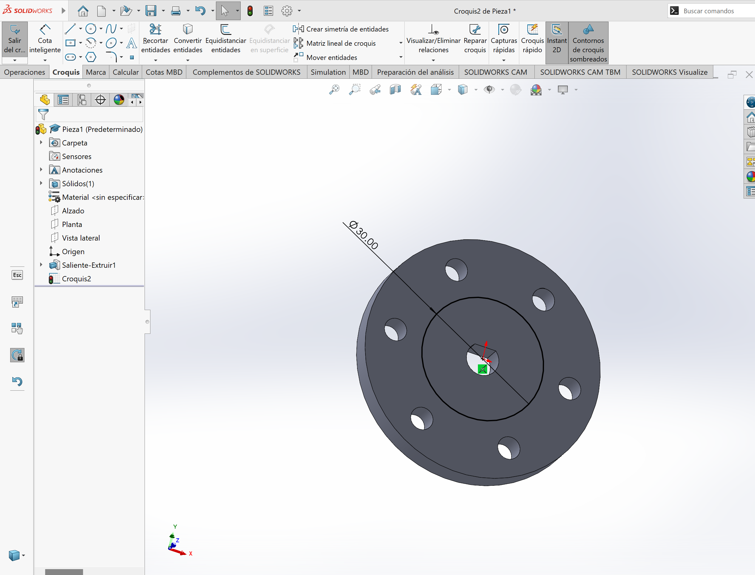
We then create two concentric circles and set their dimensions using the "smart dimension" tool. We then convert one of the circles into a constructive line.
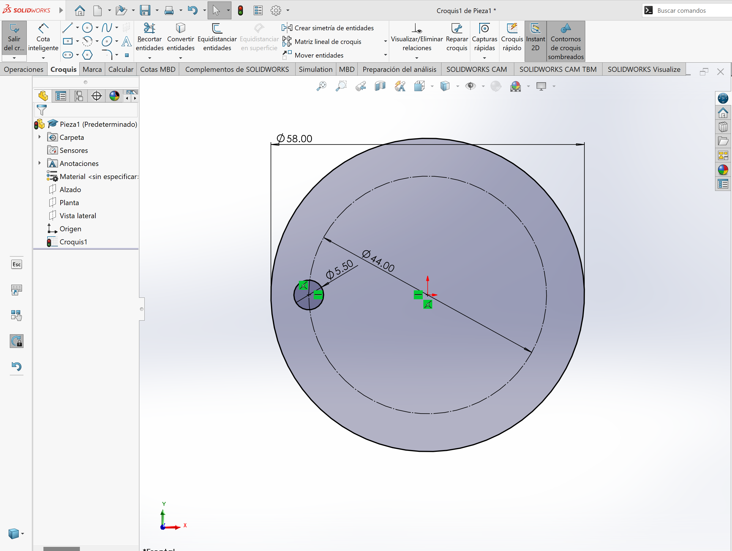
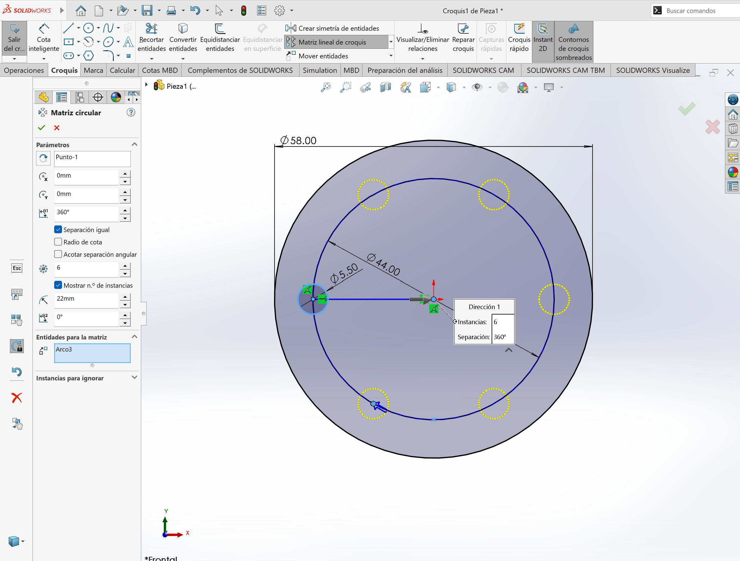
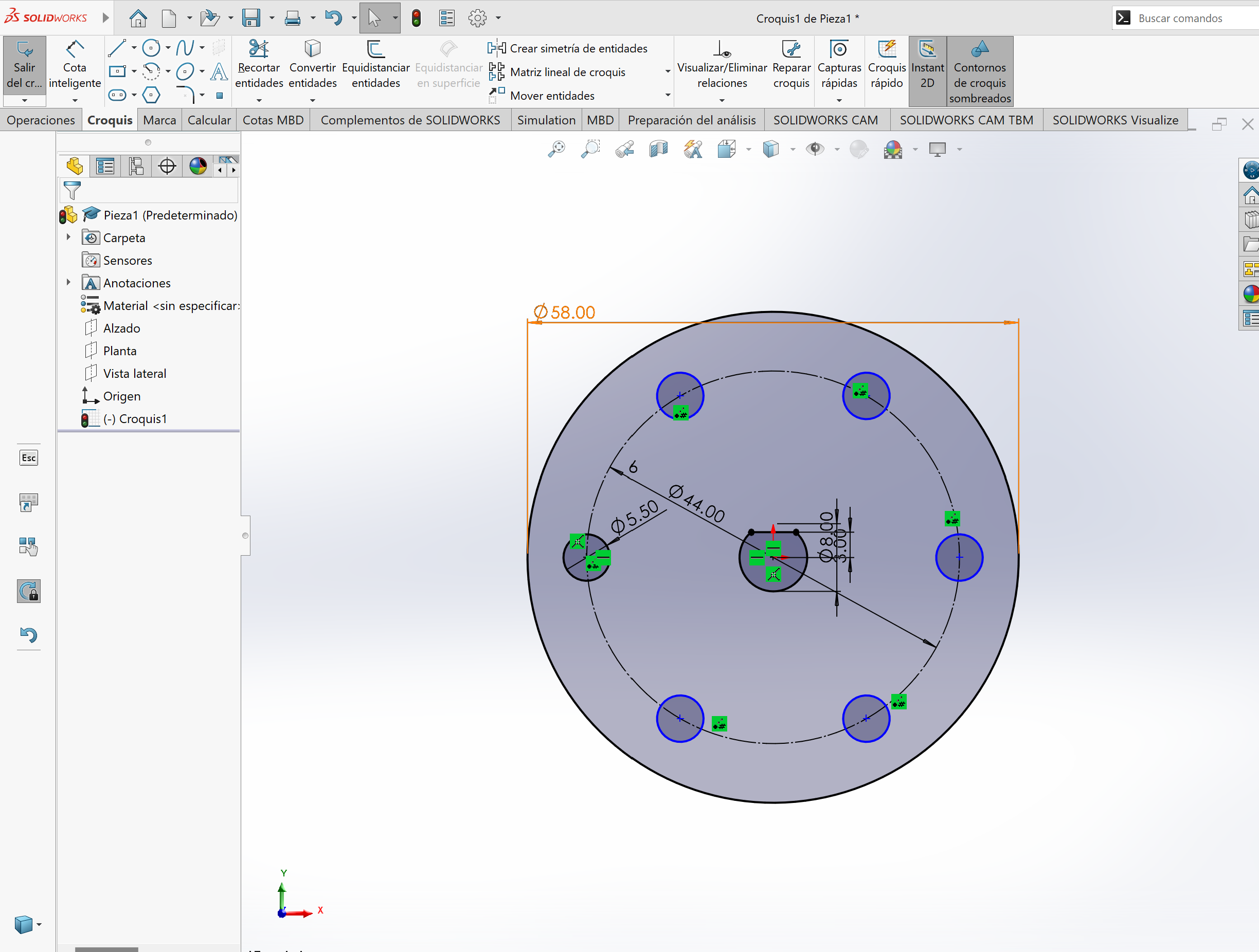
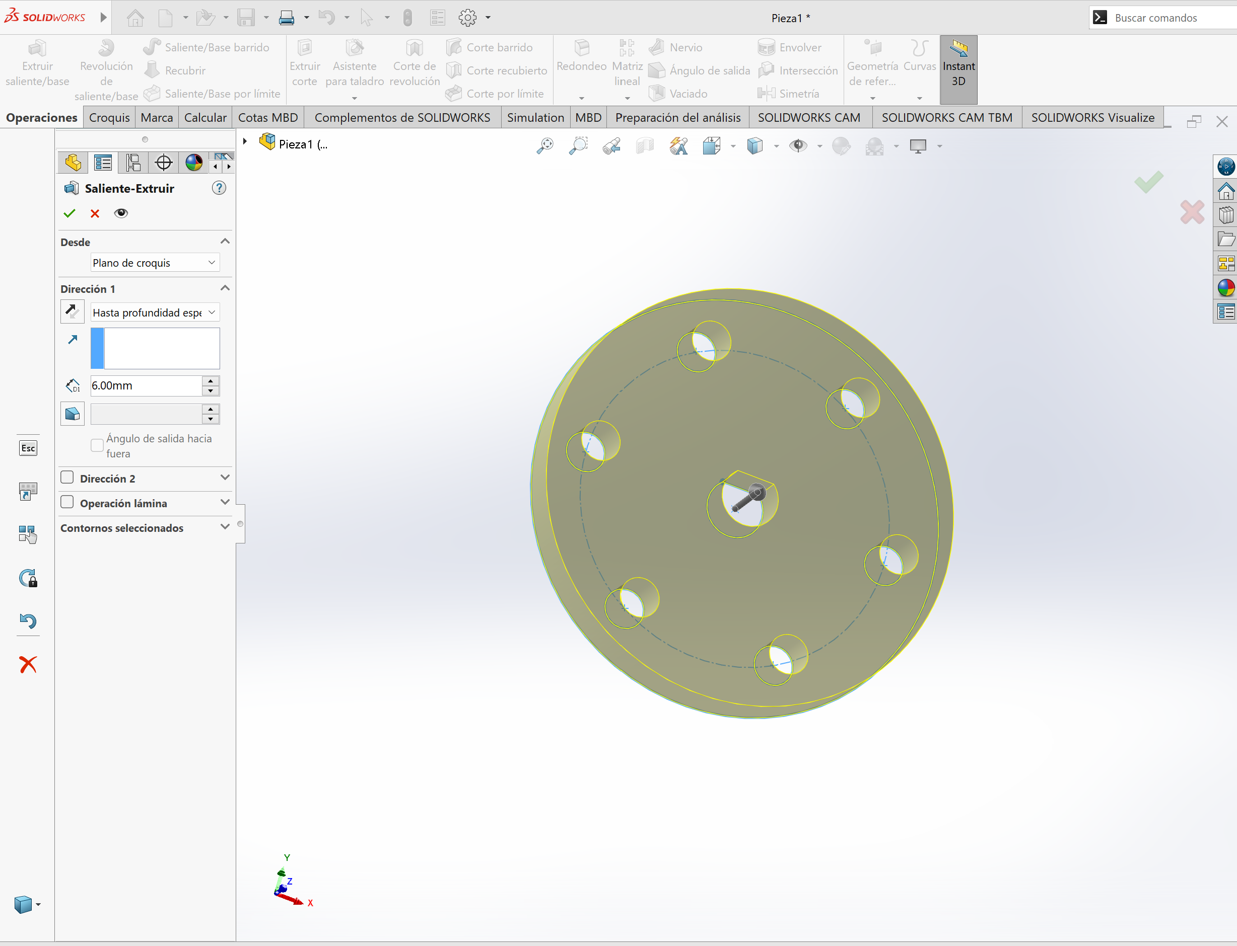
Then create a smaller (5.5mm) circle coincident with the constructive circle, and use the circular matrix tool to create 6 instances of it along the circle's trayectory.
Let's now create the center axis mount and extrude this sketch 6mm.
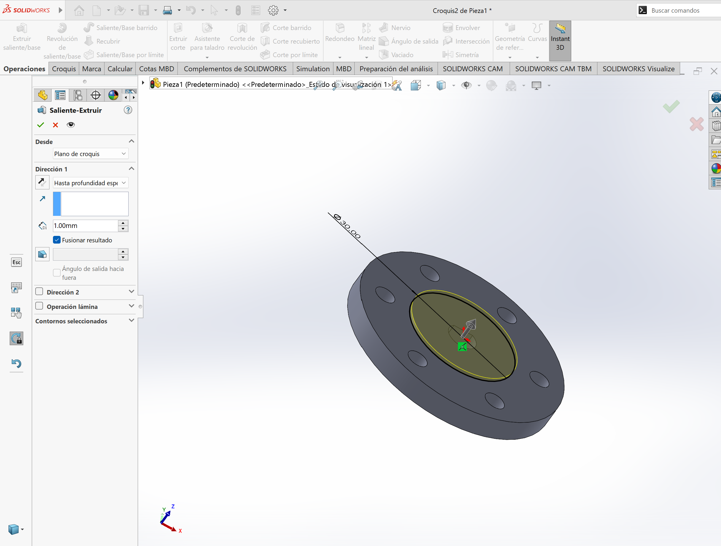
Once the main part was extruded, I created a second sketch for a little notch the piece needs. This notch was drawn and extruded by 1mm.
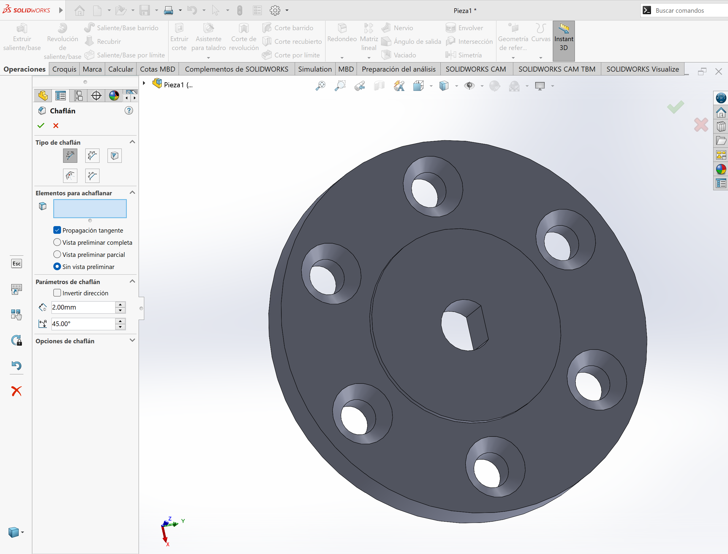
To finish the part I used the chamfering tool to create an area for some socket screws to fall in:
Even though I already have experience with SolidWorks, OnShape poses an interesting cloud-based alternative whose workflow is very similar with that of SolidWorks, making the learing curve much easier for me.
But why would I even bother with learning another CAD software if the one I already know how to use is available? Well, the cloud-based system and its ease of obtaining educational licenses makes it very attractive for me: Someone who has to be moving all the time and has to be able to work and sync my data in up to 4 computers throughout my day.
Also, OnShape is easier on computing resources, allowing me to comfortably work in my designs on my laptop, not having to be forcefully tied to my more capable desktop computer in order to have a fluid and productive experience.
Of course, OnShape has it's limitations, Finite Element Analysis and Realistic Rendering is a no-go with this software (at least using an educational license), but, for most of the purposes of FAB Academy and most of the work I do, OnShape gets the job done with extra points on practicality. I wont be leaving SolidWorks behind though, throughout my progress on FAB Academy you will see how SolidWorks helps me with rendering product images!
Basics of Designing on OnShape
Once you've signed in and created a new document using the big blue button on the top left corner, you will land in a 3D environment, classic of virtually every 3D-capable CAD software.
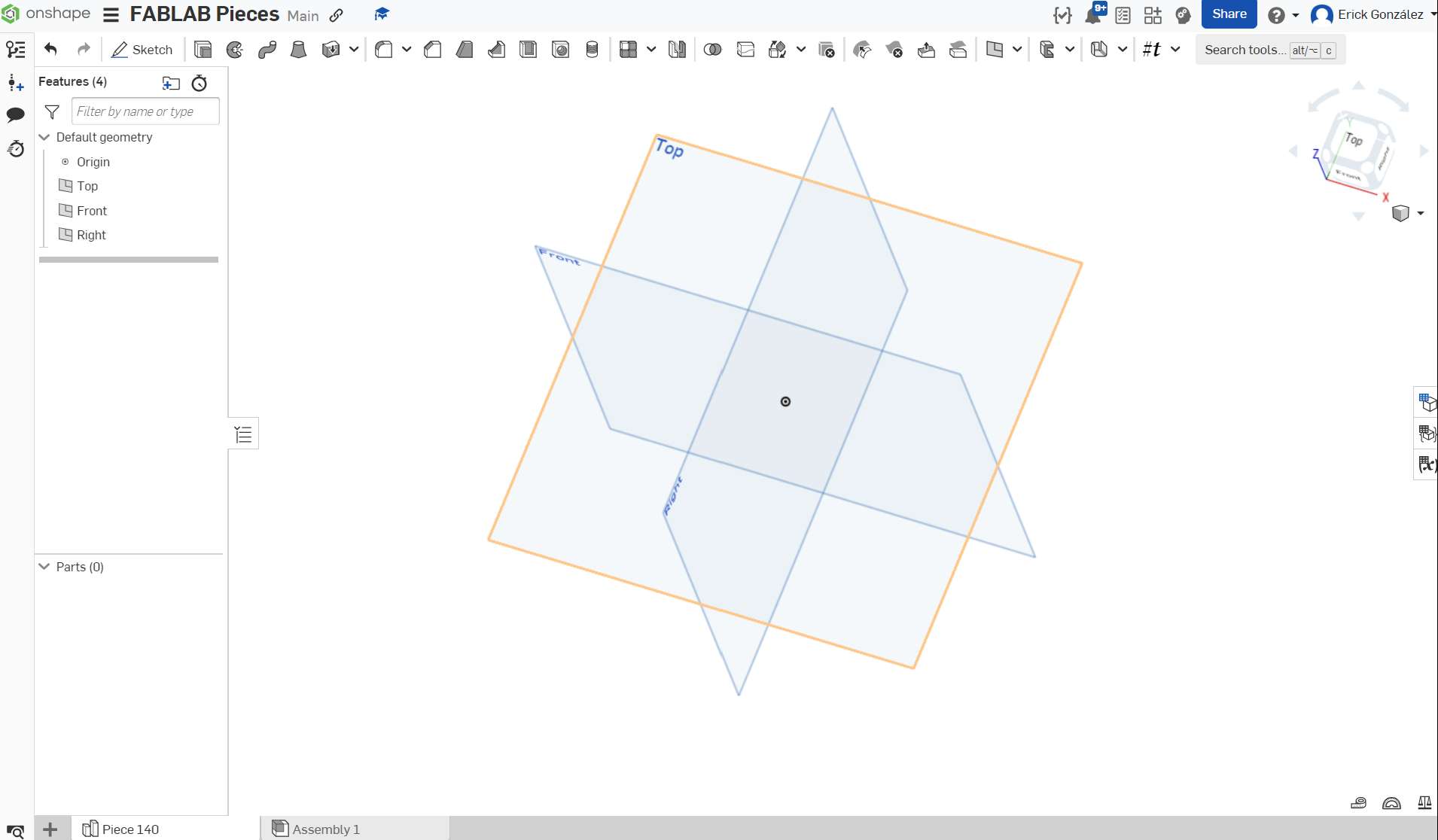
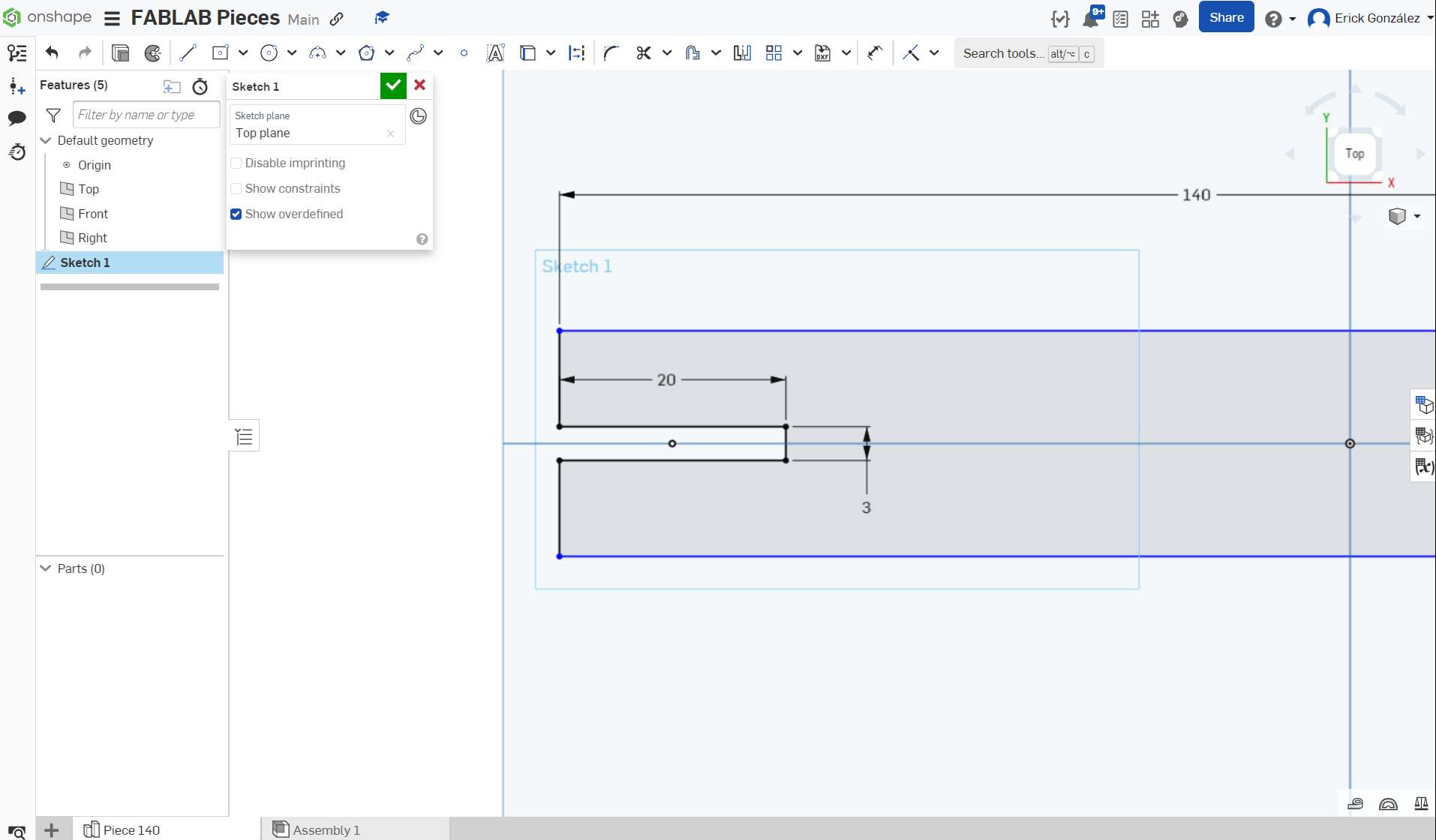
Let's create a simple piece for my design of an MDF building piece set. Click on "Sketch" and select a plane over which you'll start drawing. In my case, I chose the top plane. Once the plane is chosen you get access to all the drawing tools, lets create a square!
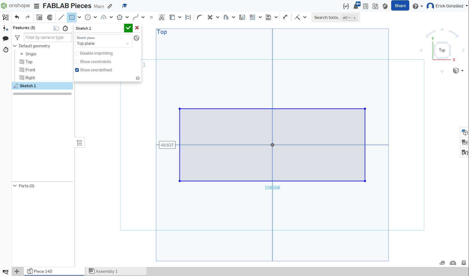
The square is now drawn from the center, but it has no specified dimensions, lets size it to 140mm long and 20mm wide using the dimension tool!
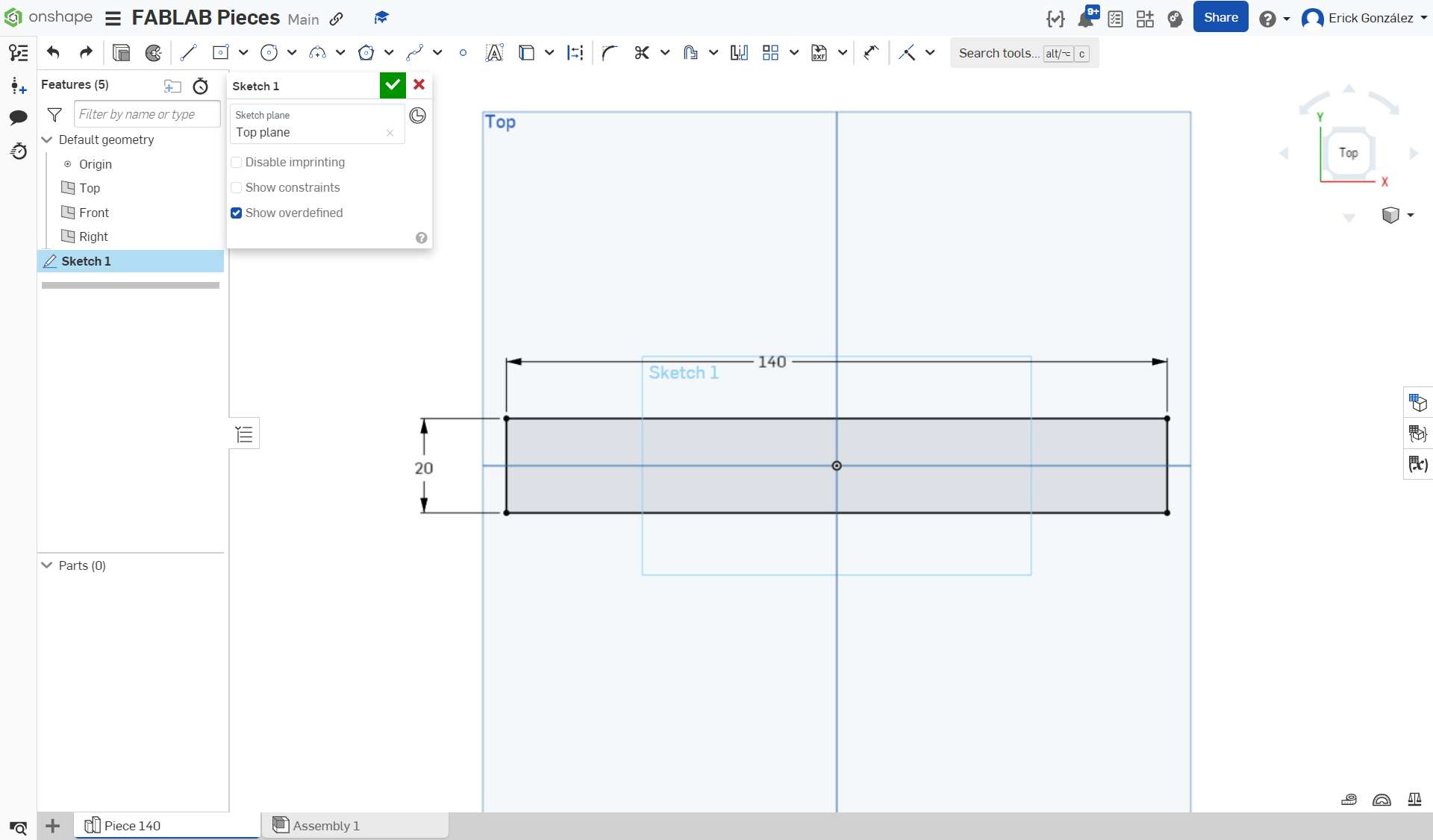
Now that the square is parameterized it's lines have gone black instead of blue, meaning those have now dimensional limits on them. Not all lines have to go black, but it is certainly desirable in order to minimize the possibility of lines shifting places / dimensions in order to accomodate changes made to the sketch. With that being said, let´s draw some identations for the pieces to connect with each other:
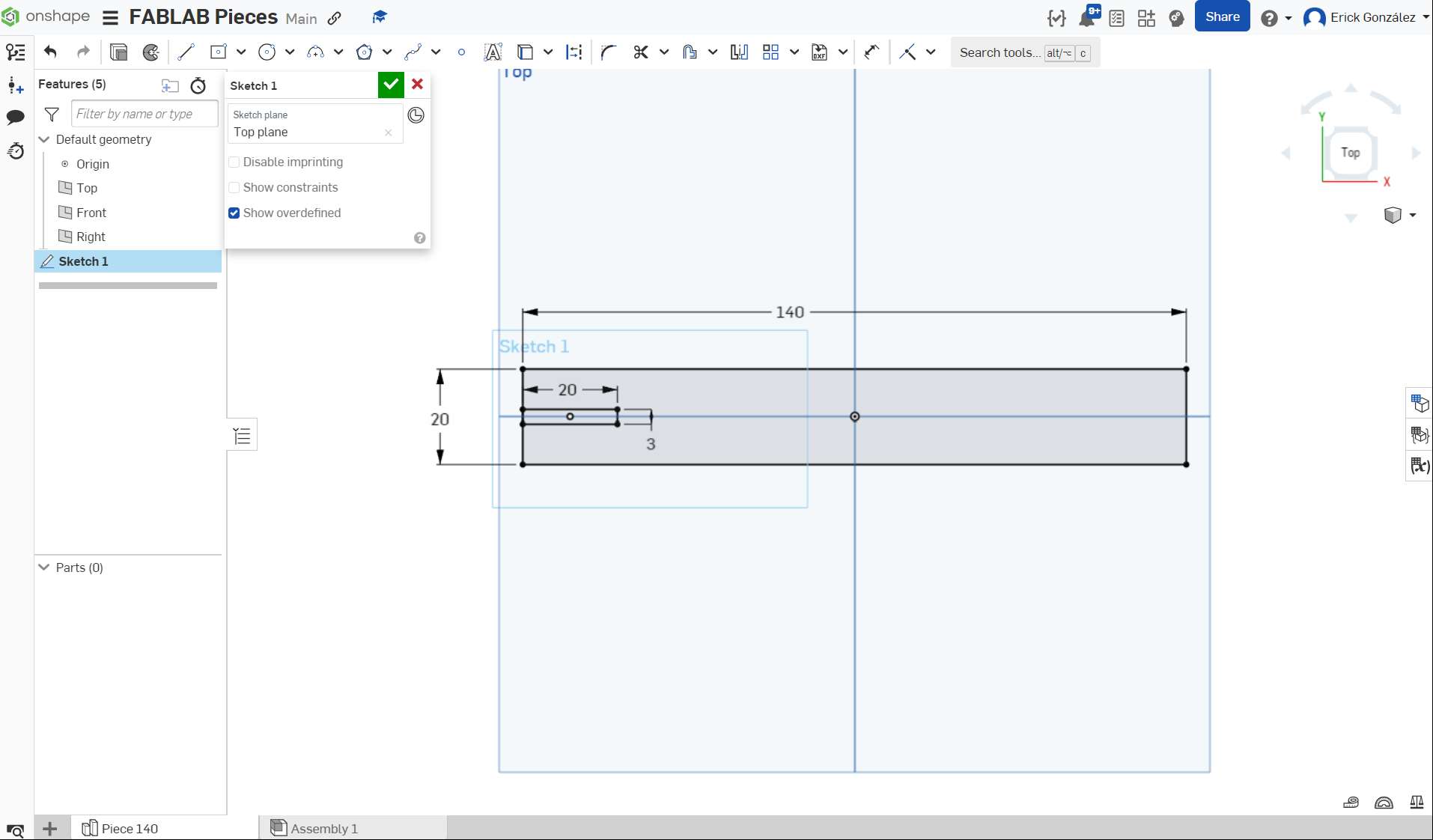
The dent is dimensioned to 20mm long and 3mm wide, as I'll be eventually using 3mm MDF to make these pieces. But we have a problem, we want that square to be open so we can insert other pieces, and that's when we use the "trim" tool which allows to remove sections (delimited from point to point) of lines we dont want in our sketch.
Now the dent is open, we have to create another three slits on the design. We could do this manually by drawing them individually, but luckily OnShape gives us a useful "Linear Pattern Tool" to create as many shapes we want along a path (in this case a straight line) while maintaining a specified spacing between them. I created 4 slits, spaced 40mm (beggining to beggining) using this tool:
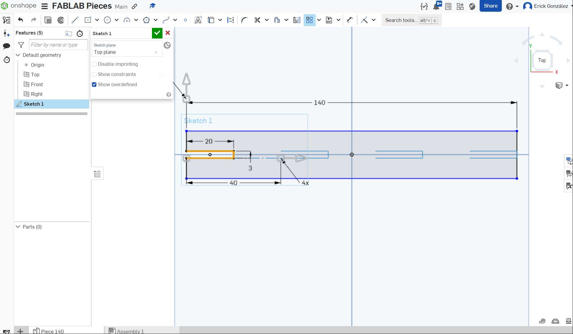
I have created all the slits I needed, so the last thing to do to this sketch is to trim the unwanted lines. Once we've done that, we confirm the sketch with the "green tick" button.
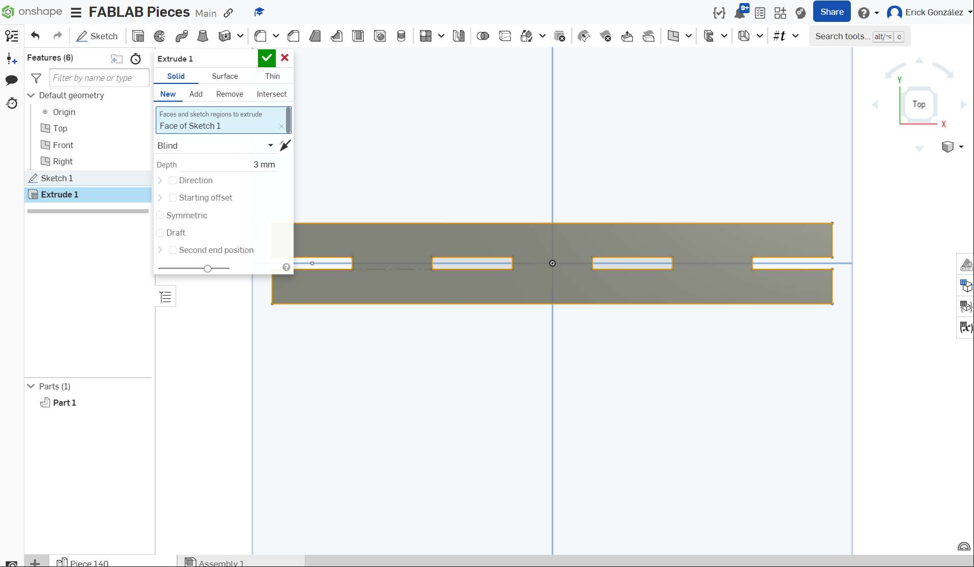
When having a finished sketch we can extrude it using the provided extruding tools, or simply export the .dxf file for laser cutting. In this case I want both, a 3mm extrusion to visualize how the piece will look once its cut, and the .dxf file export to do the actual cut. First let's do the extrusion: Right of the "Sketch" button, we find another button with the icon of a cube, that is the extrusion tool. To use it we have to select our previously drawn sketch (it has to be a closed shape) and click then on the extrusion tool button; a window will pop up, asking for an extrusion depth, which in this case is 3mm (the thickness of the MDF I intend to use).
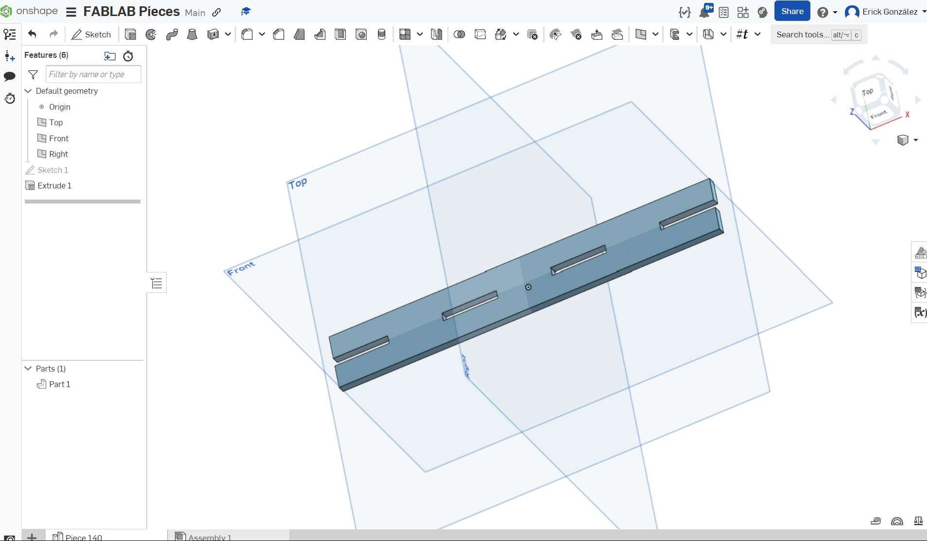
Once this is done, the final 3D piece is complete! Albeit, a very simple design, I think it shows well the very basics of using OnShape.
The process to export our .dxf file for laser cutting is very straightforward, we just find the sketch we designed in the left-side panel, we right click on it and a small menu will open, we select "Export as DXF/DWG" another window will open, where we get export options for the DXF file, we select the "2018" version and hit the "Export" button. The file will be then automatically downloaded!
Getting a bit more complex!
Creating more complex 3D models often means we have to create multiple sketches that build up on each other. In this example I will be creating the same mechanical piece I did in the beggining using Solidworks, a brake disk mount that will be used in my final proyect!
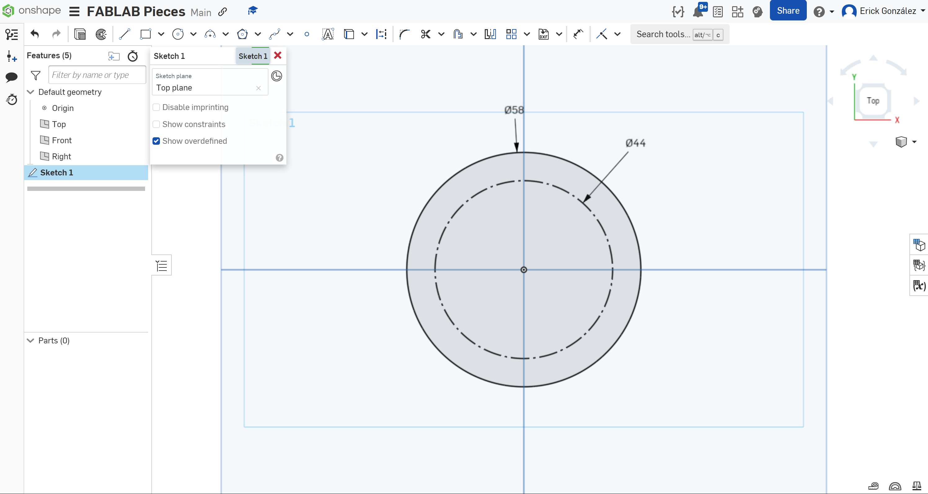
I start by creating a Sketch on the top plane, and drawing on it two concentric circles. Then I select the inner circle, and convert it to a constructive line, using the "Construction" button or by pressing the "q" key. Constructive lines do not form part of the design as is, but serve as useful reference points to place or intersect other lines that do appear on the design. In this step I also defined dimensions for the inner and outer circles.
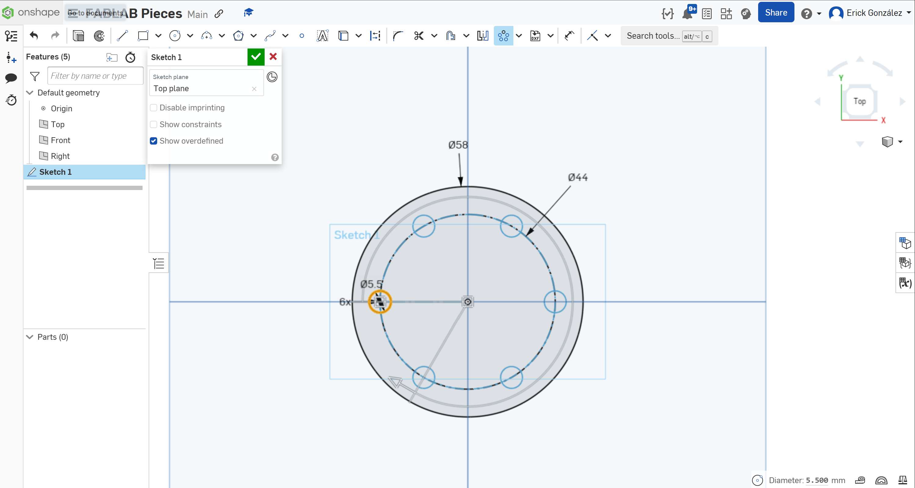
After drawing the concentric circles, I drew another smaller circle in the intersection between the plane's horizontal middle line and the constructive circle, then, using the "Circular Pattern Tool" (similar to the previously used linear pattern tool) I created six evenly separated circles, that follow the constructive circle's circumference. These holes serve as mounting points for screws to pass through without a thread.
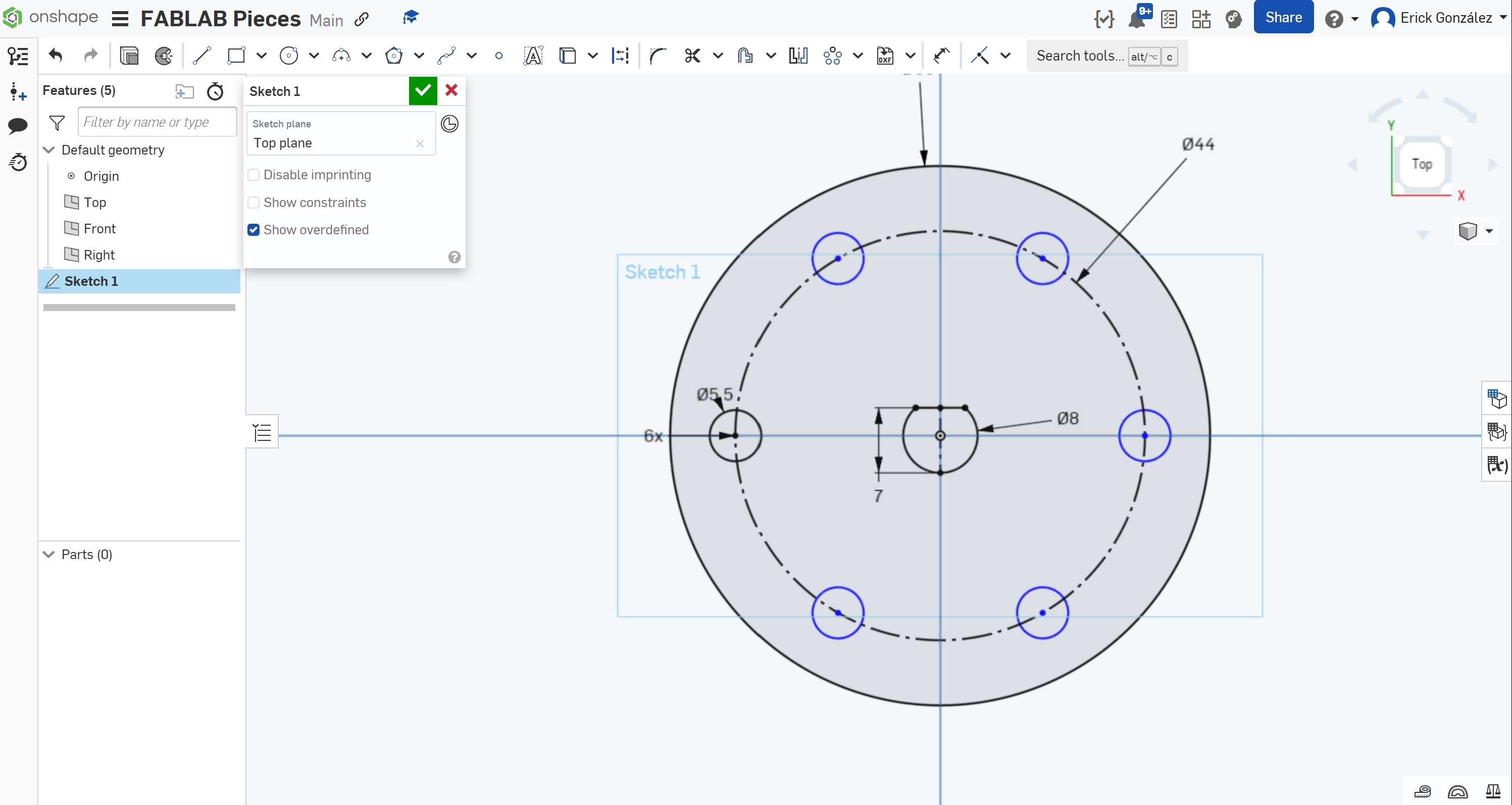
After the circle array has been created, I then drew another circle for the motor's axis in the center of the design, but with a small dent created using a constructive line:
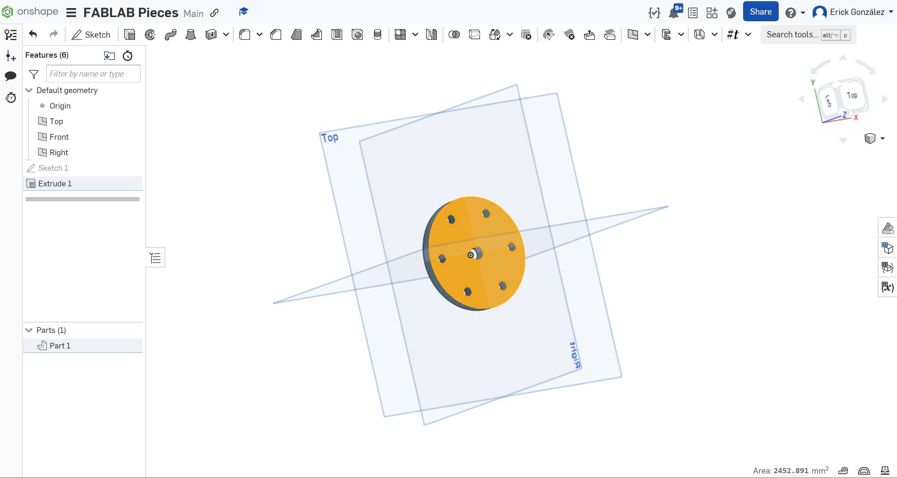
Once this is done, we have to extrude this shape to a 6mm thickness. To do that we follow the exact same procedure we did in the previously made extrusion.
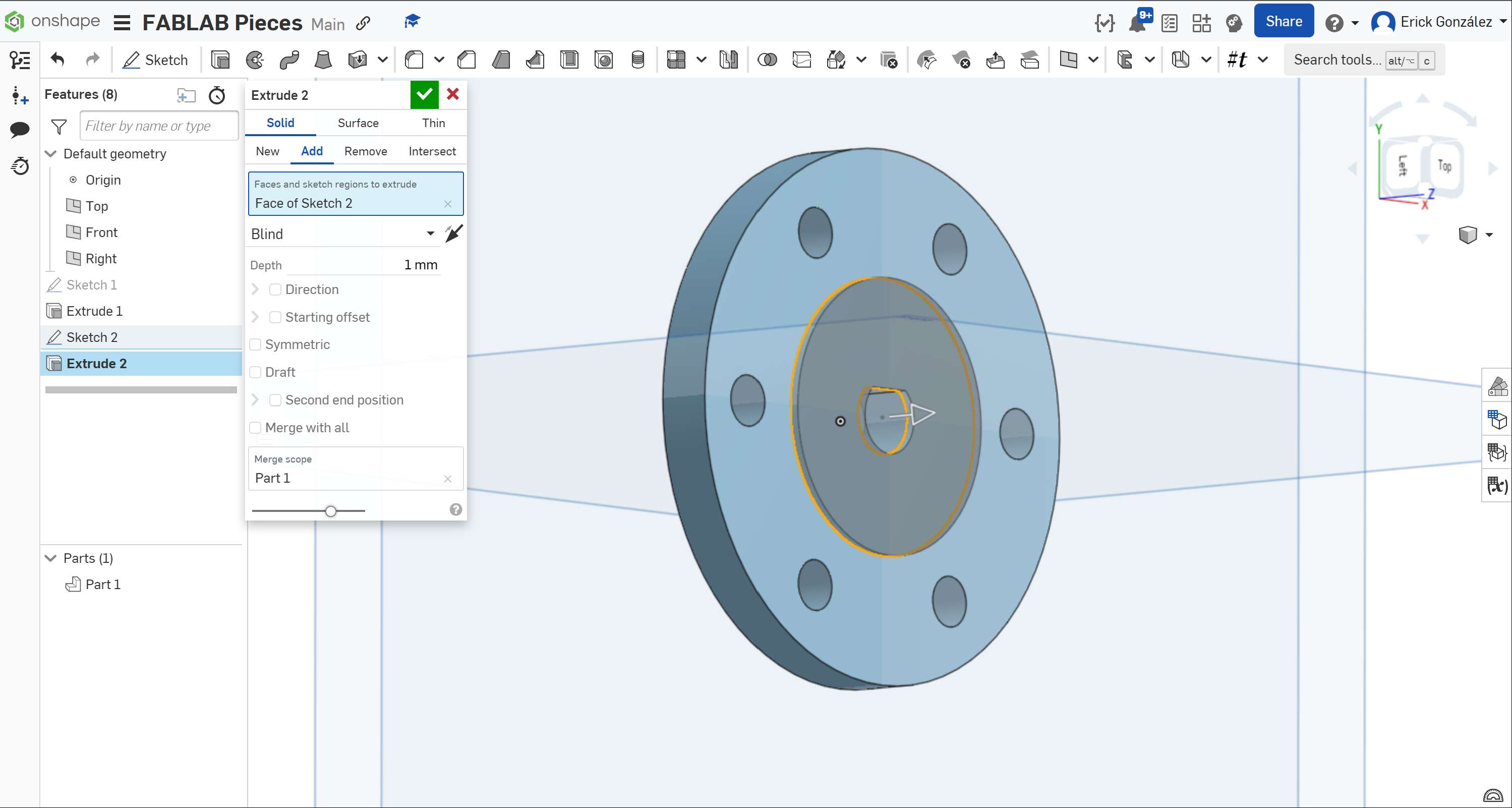
With the extrusion made, we then select one of the object's flat faces, to create in it a new sketch in order to make a small protrusion.
On the selected face we draw another concentric circle, this time measuring 30mm. Once it is drawn, we extrude it to a 1mm thickness.
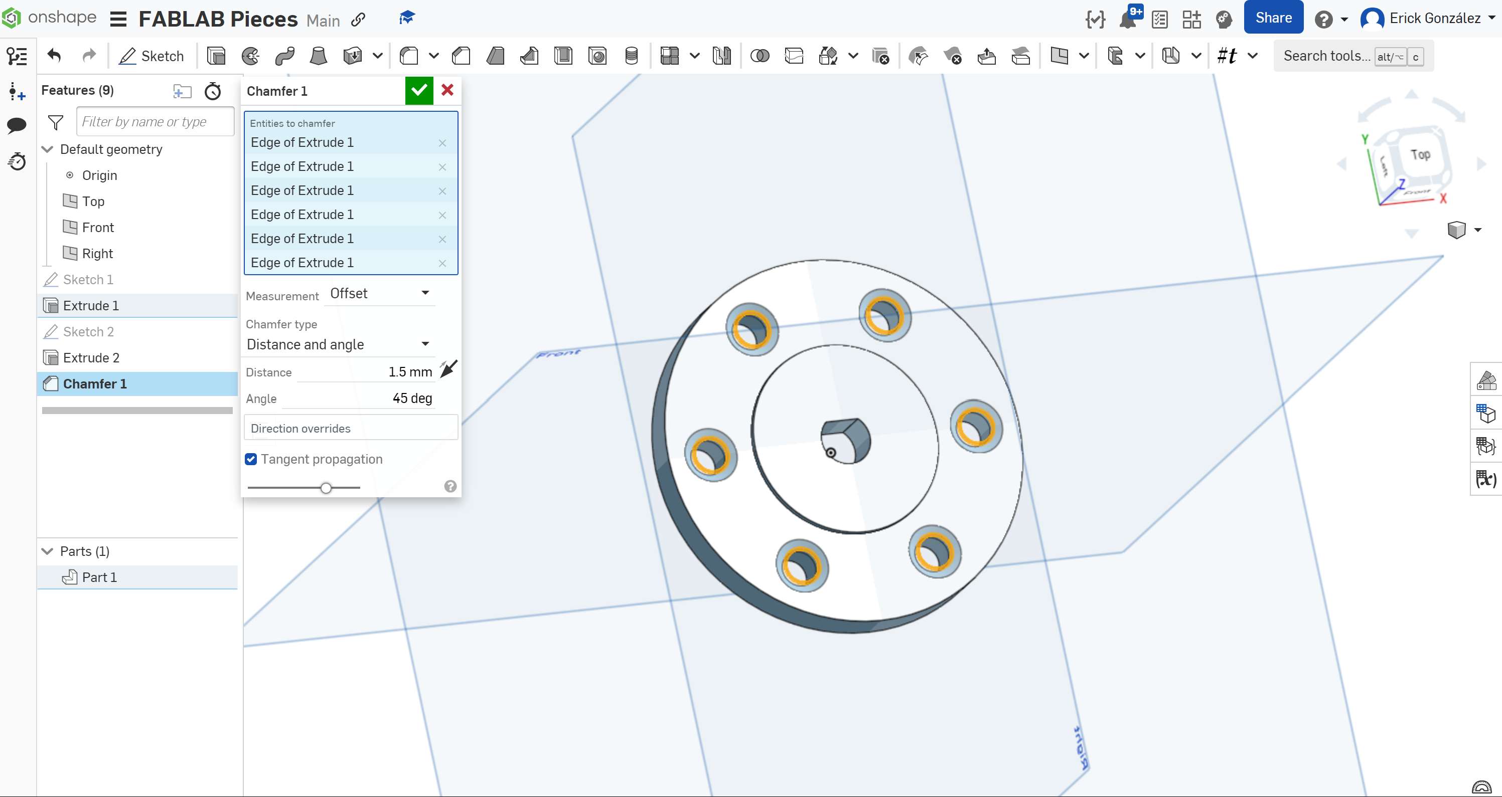
The piece is almost finished, but we need a way to hide the screws' heads once they pass through the mounting holes! We use the "Chamfer" tool directly on the 3D piece (outside any sketch drawing interface) we click on the tool, select a 45° degree, 1.5mm chamfer, and click on all the edges we want this applied to, in this case, only the circumferences around the holes is chamfered.
We have now finished this second piece!
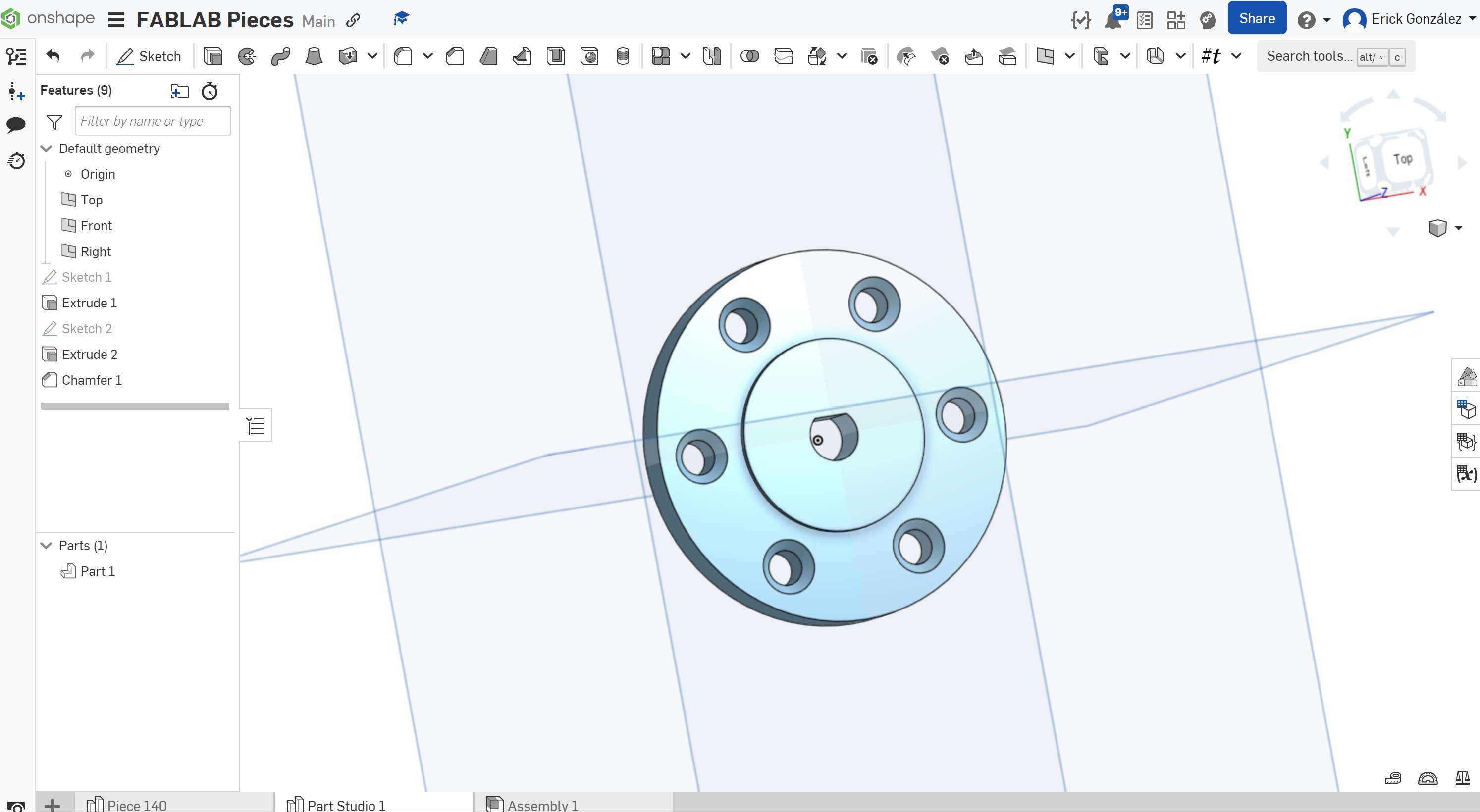
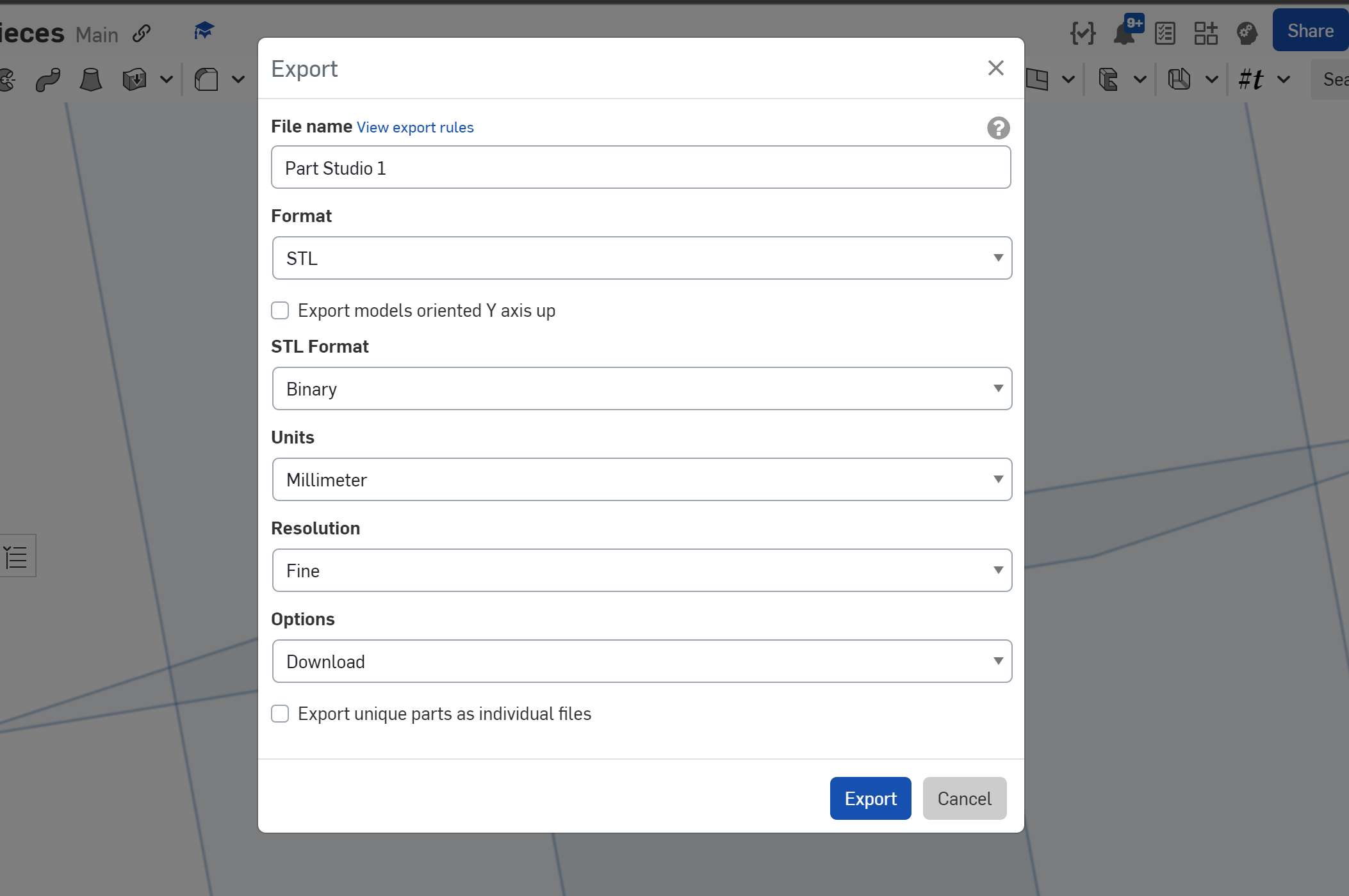
We can now head down to the "Tab Menu" below our design space, right-Click on this piece's tab and click export using the following settings:
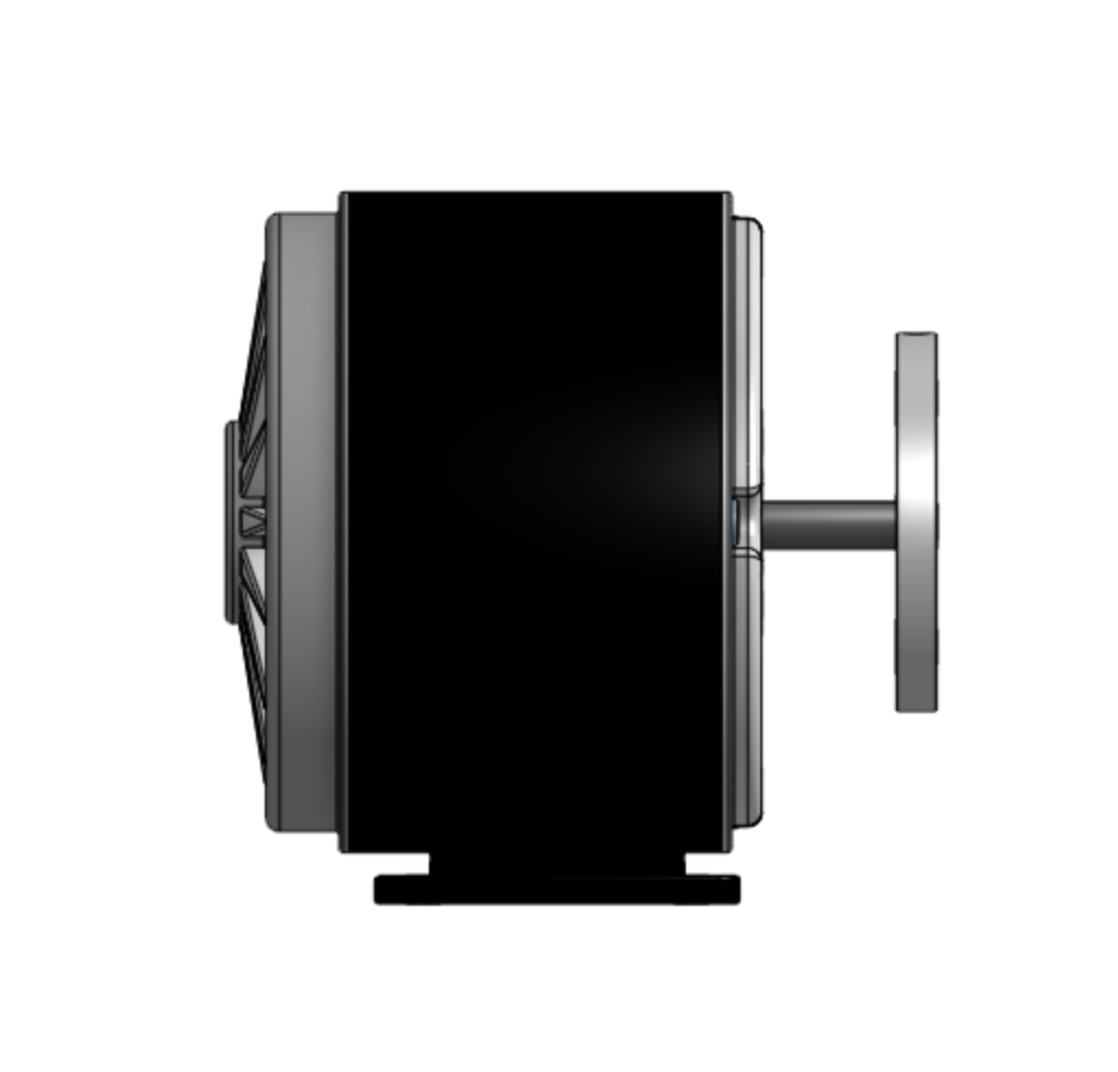
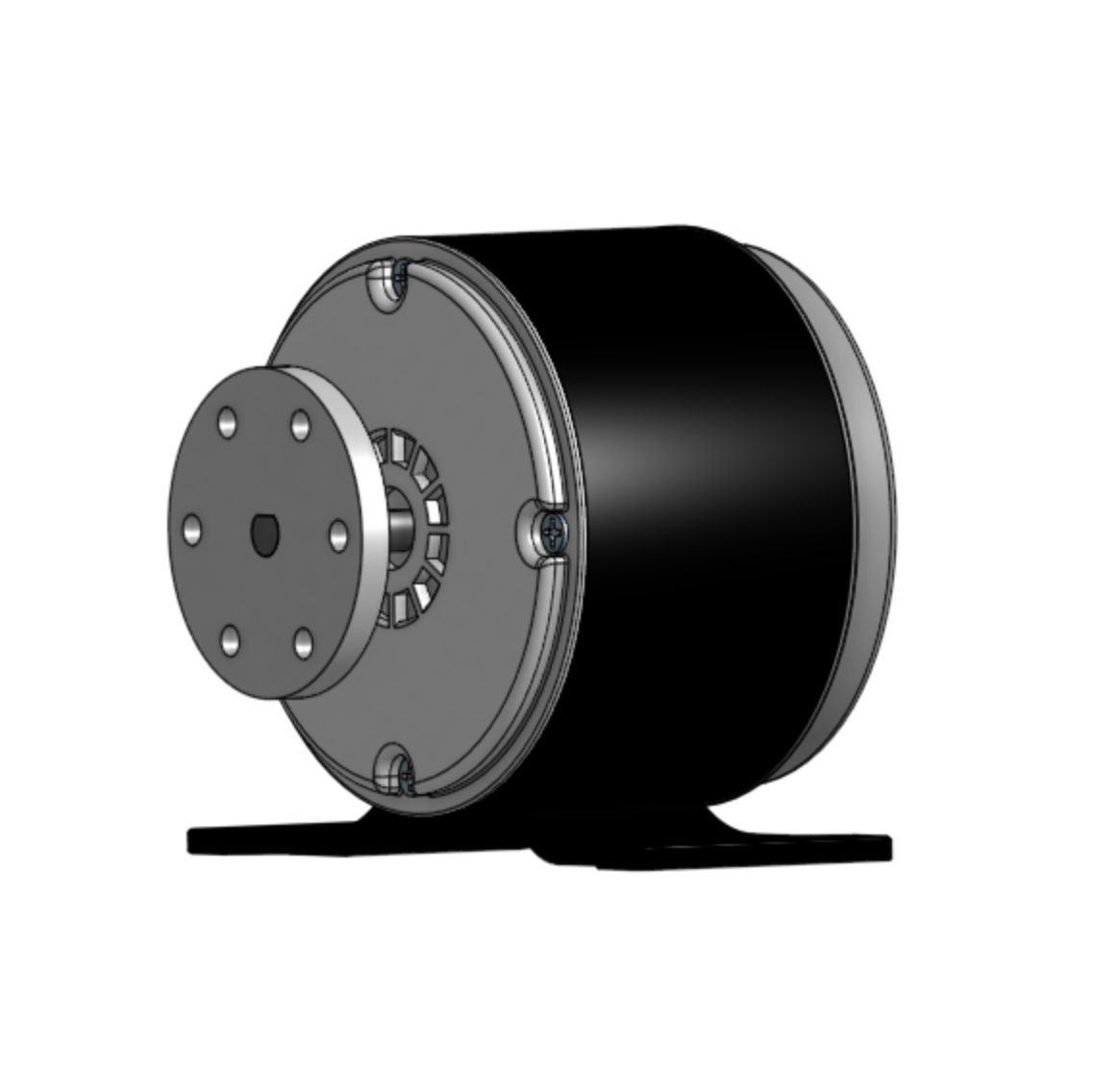
To put in context the implementation of the circular adapter on the motor's axis, here's a 3D assembly showing both parts connected.
Thank you for taking a look into my 2nd week's progress!