

My Final Project: The Campus ROVER
P1 - Powertrain
The first thing to start designing is the powertrain, the part of the scooter that actually makes it move, and I would argue that is the most important aspect of my proyect. On a drawer in my FABLAB I found two 300W DC motors, on which I will be basing my first design. The original plan (as shown on the hand-drawn sketch) contemplated the motors mounted directly on the wheels' two axes, but I quickly saw that plan to be unviable as the motors didn't have enough torque by their own to start the scooter moving; also, all the weight of the user would fall on the motors' axes, what would quickly damage them.
So I devised another plan, on which I provided a mechanical advantage to the motors and also removed the weight load from the motors' axes. The following design, contemplated a chain and sprocket mechanism in a 3 to 1 configuration, taking the maximum torque and speed of the motor (1Nm @ 3600RPM) and multiplying the torque rating at the output, at the expense of speed: (3Nm @ 1200RPM). I designed the pieces for them to be made in machined aluminum, and installed four rowlocks and dual 5/8" high carbon steel axes, one for each motor.
The plan for manufacturing the needed custom pieces in aluminum also flunked, as in our FABLAB we apparently don't have the means to work with metal the way I needed to, and manufacturing them somewhere else, was prohibitely expensive. Because of this, I modified my designs, and made them so they could be fabbed on a 3D printer and still withstand the forces involved in the scooter's mechanism.
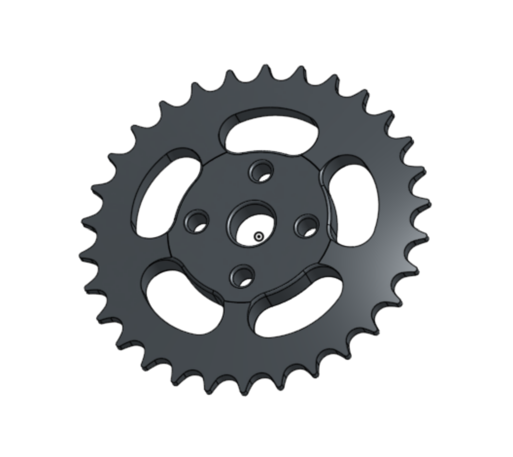
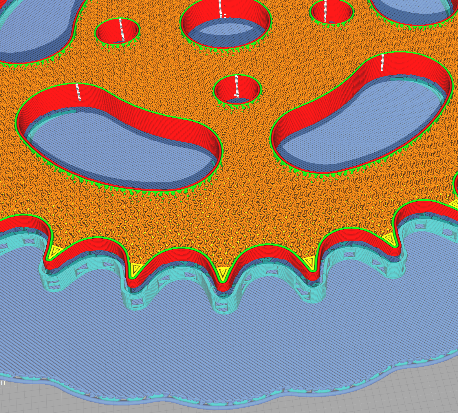
The chain main and secondary sprocket consecuentially changed, from a 2D design made to be plasma cutted from sheet metal, to a 3D model designed to be printed. Printing it in PLA using a 50% gyroid infill resulted in a very strong and mechanically capable part.
Once the main parts were designed, I made a first assembly of the whole powertrain for a single wheel, both wheels are identical, but mirror mounted on the steel axis:
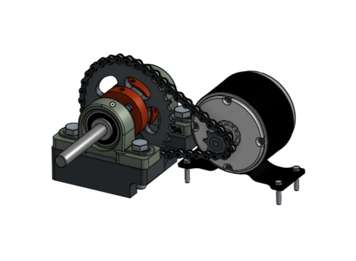
I actually assembled and tested live the whole mechanism, and came with a series of problems that had to be solved:
- The gears and wheel assemblies slipped along the axis when submmited to high-torque loads.
- The chain assembly produced a lot of noise.
- It was difficult to align the large sprocket correctly with the chain.
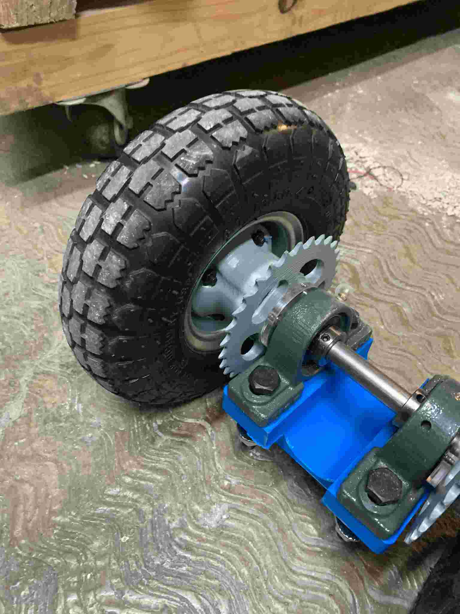
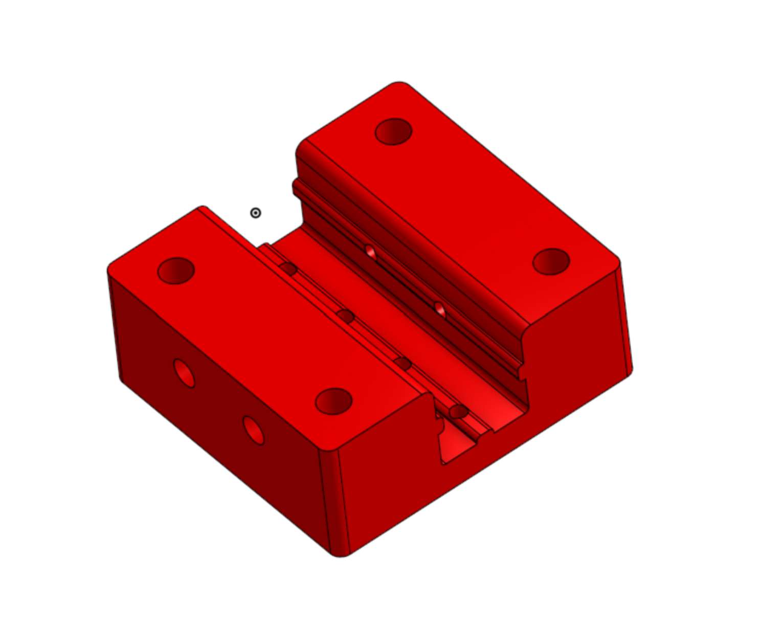
To solve this issues I tried a lot of corrections to the current design, from increasing the number and width of set screws used to fix the pieces to the axis, to decreasing 3D printed tolerances, none of which made an actually difference. So, in order to definitely solve those issues, I changed mi point of view: Instead of making the axis turn the wheels, why not transfer power to the wheels directly and use the axis just as support? With this approach, many things were simplified, and the mechanical principles were the same, so no need to change the design of my sprockets. I needed new designs though, a way to mount the sprocket and brake disks onto the wheel directly, and allow for them to spin freely along the axis, for this purpose I designed and 3D printed this two pieces:
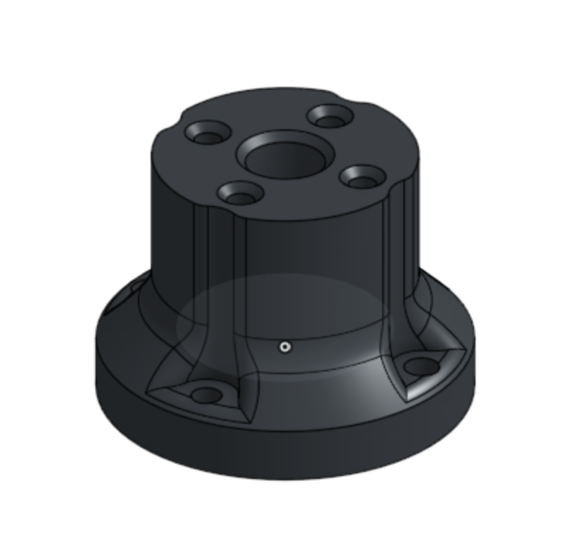
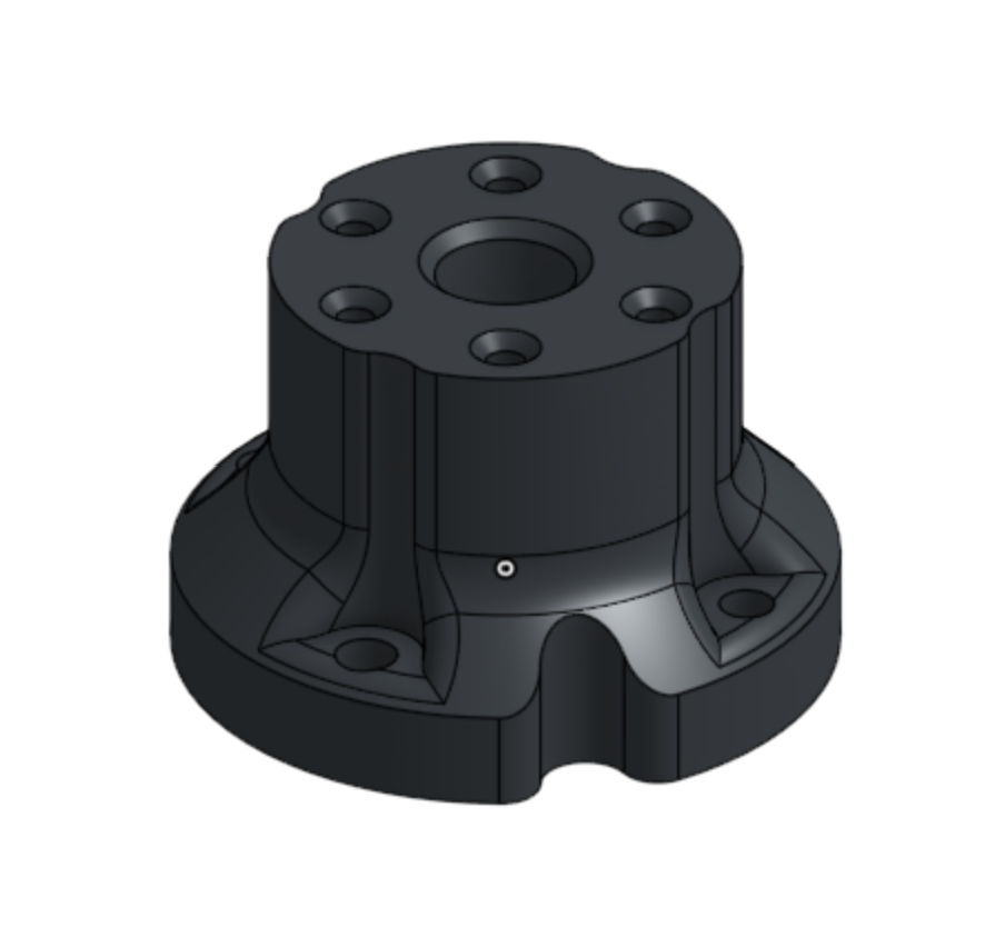
The part shown on the left is where the large sprocket is meant to be mounted along the wheel's rim, while the other part holds the braking disk, all is mounted using M5 and M4 hex screws accordingly, with their corresponding nuts inside the printed pieces. This results in the following assembly:
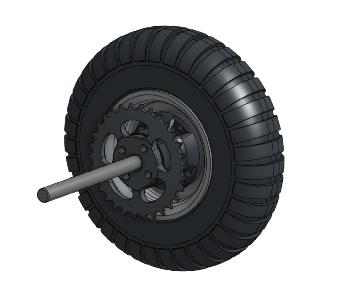
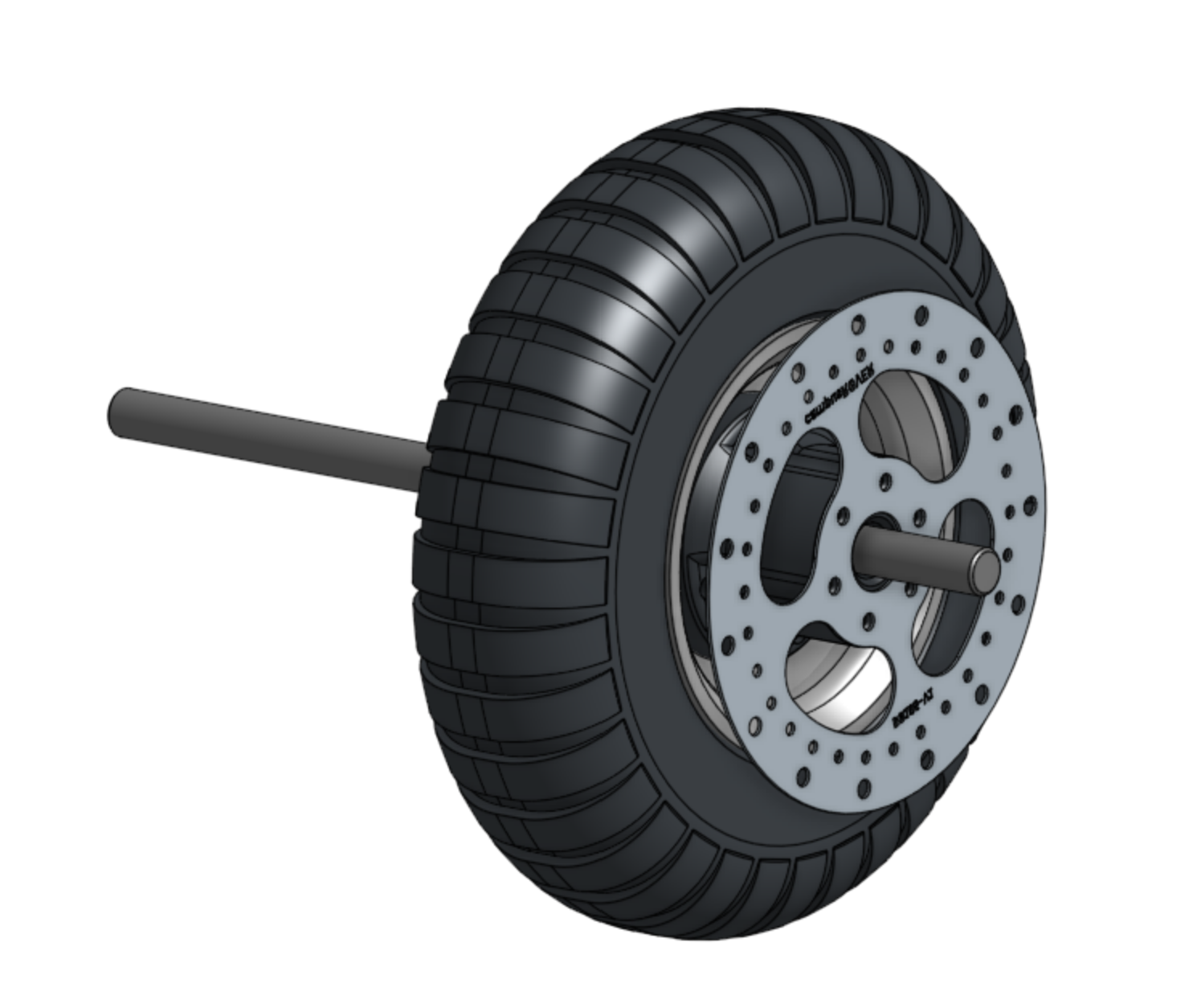
This assembly, though for one wheel only, represents the mechanism that transfers power to the wheels. In this configuration there should be no axial slipping, as power is transfered directly to the wheels and the axis just holds everything in place. To allow the wheels to spin freely and with minimal friction, a ball bearing is mounted inside each wheel adapter.
The real assembly inmediately looked more promising than the previous attempts:
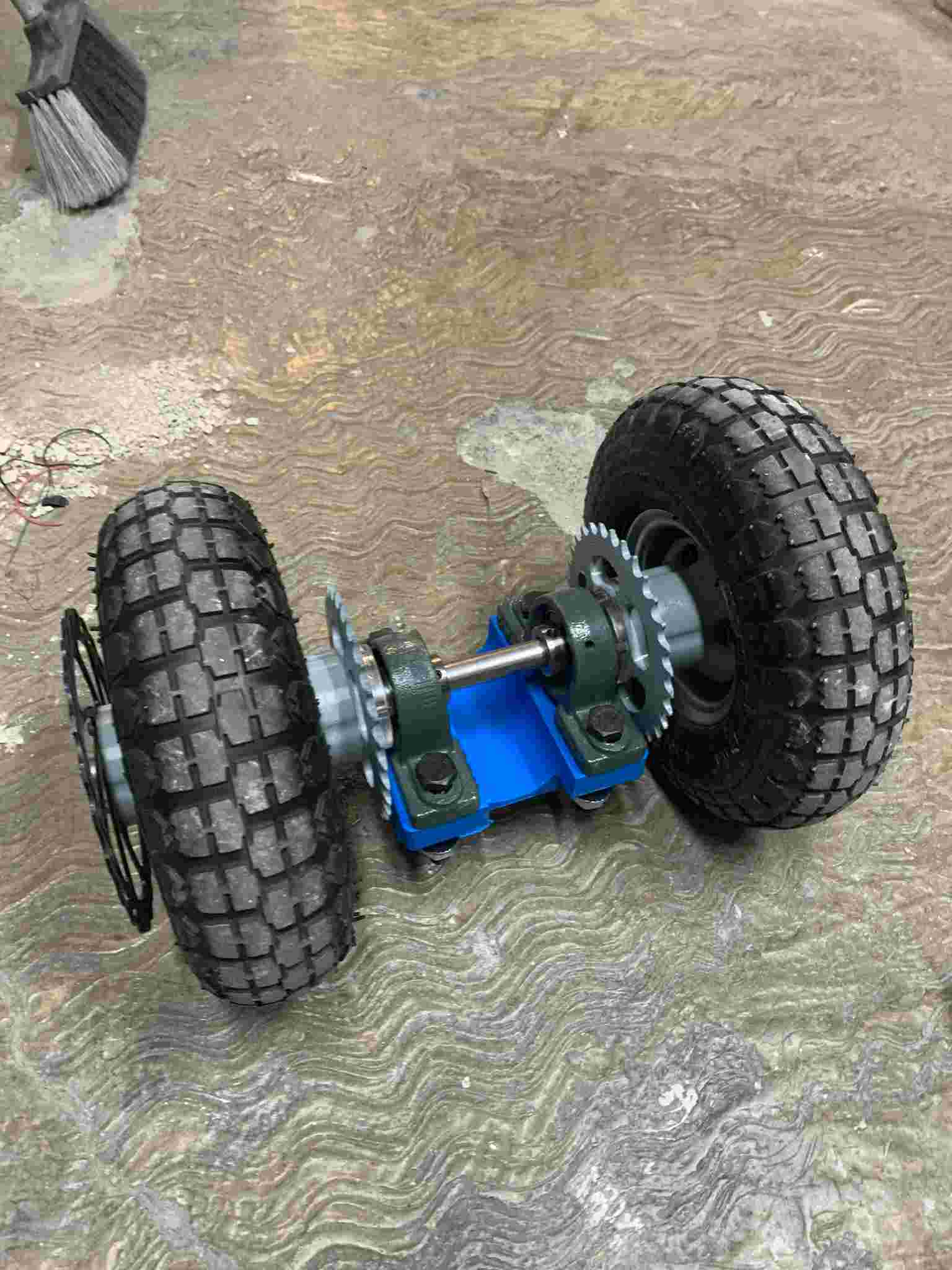
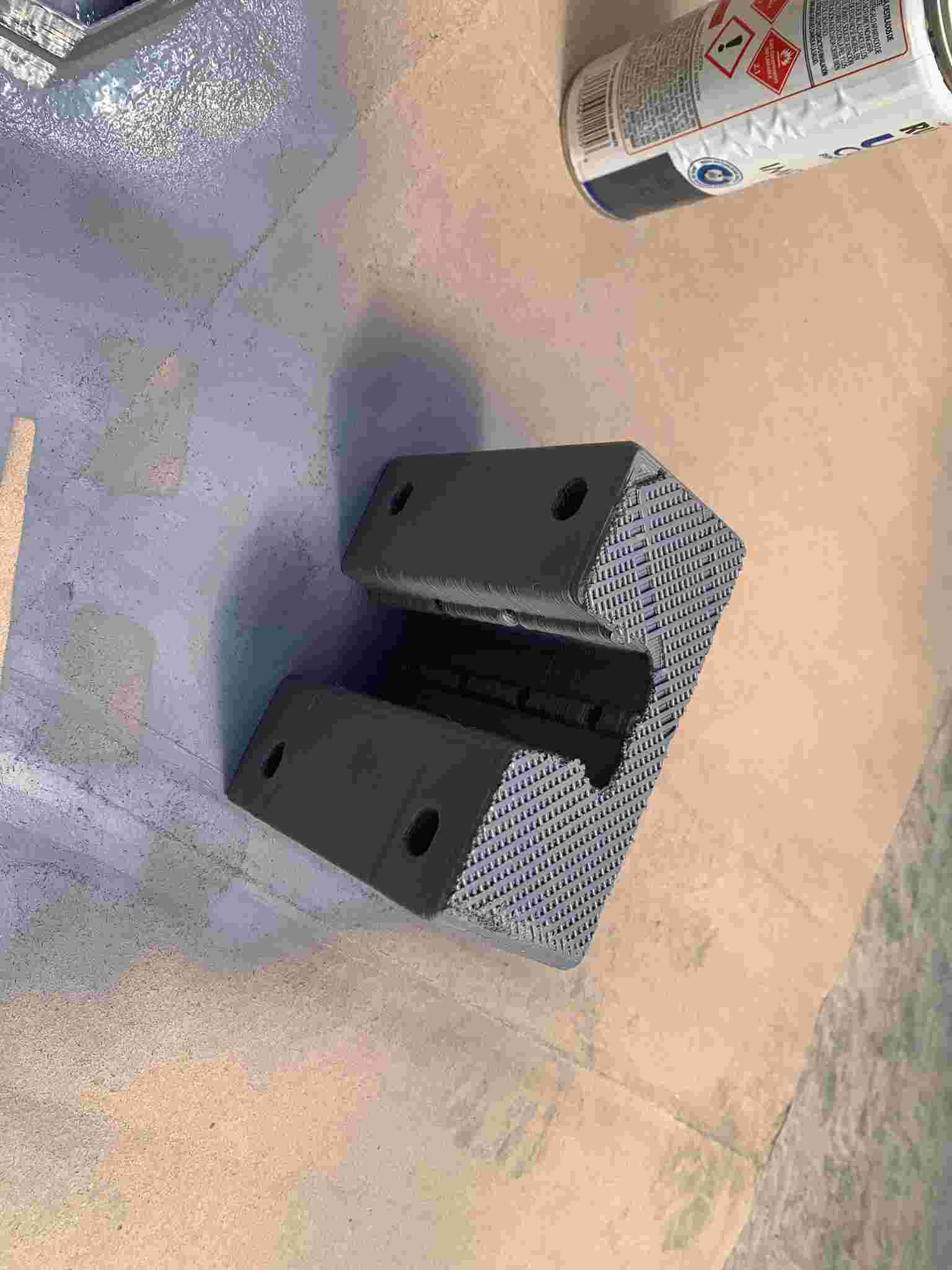
It still needed work though, so I designed another 3D printed part to mount all the powertrain assembly into a 40x40mm T-slotted aluminum profile, that would serve as the main structure to the whole scooter. I 3D printed it using a 1mm nozzle, which gave the final piece thicker walls and an overall much better resistance. After 3D printing, and because of the thicker layers used, I sanded and treated the surface with some primer, which gave it a nicer surface finish.
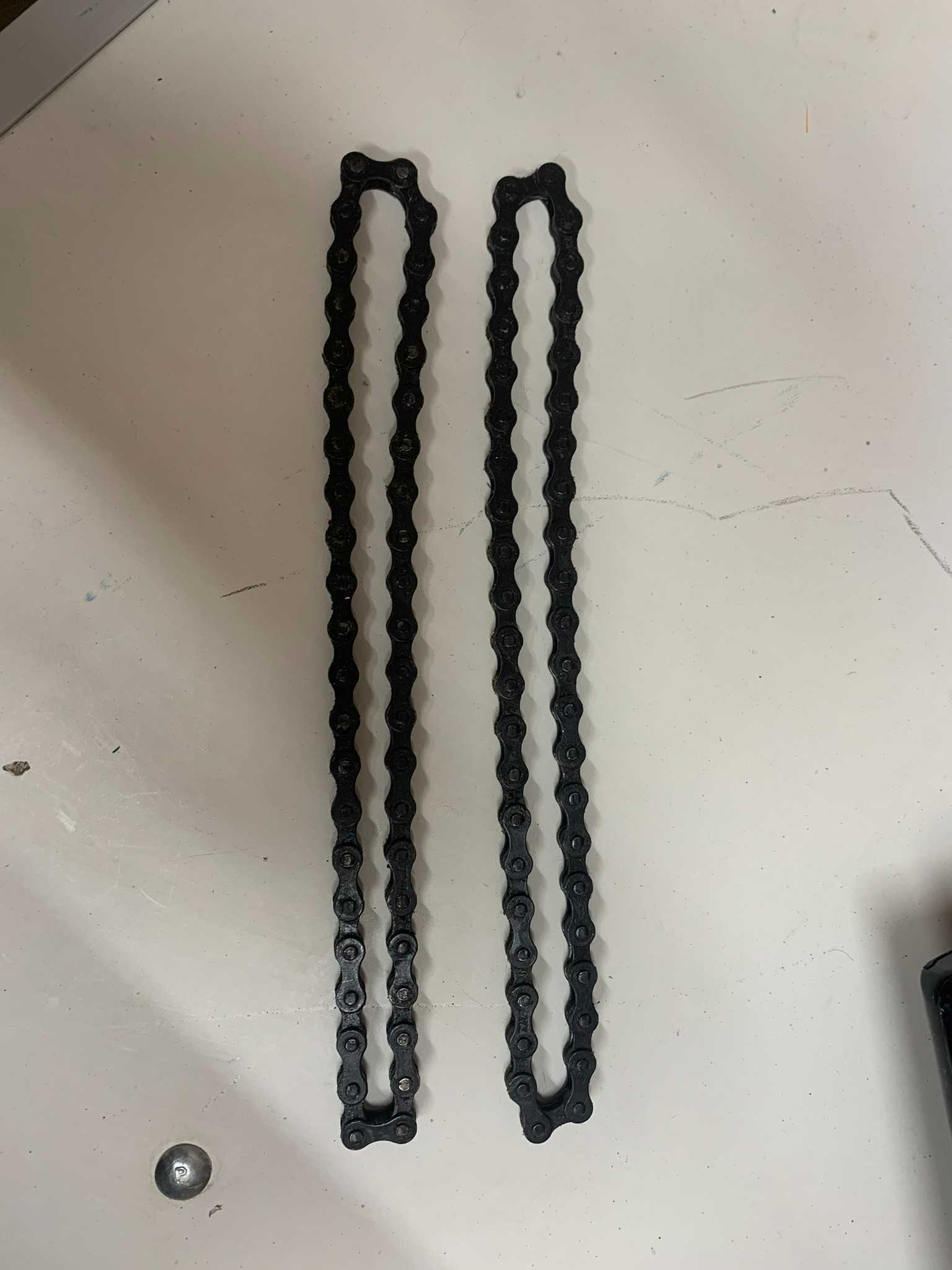
I then laser cutted in a 12mm plywood board a mount for the motors, which would be placed onto the T-slotted profile and held down by two M6 screws. The intention of this arrangement was to make the installation and removal of the two chains that transfer the power to the wheels easier, as tensioning or loosing up the chain is easily accomplished by sliding the motor assembly along the aluminum profile. I then prepared the chains to the desired and equal length and mounted everything together (including the before shown wheel arrangement).
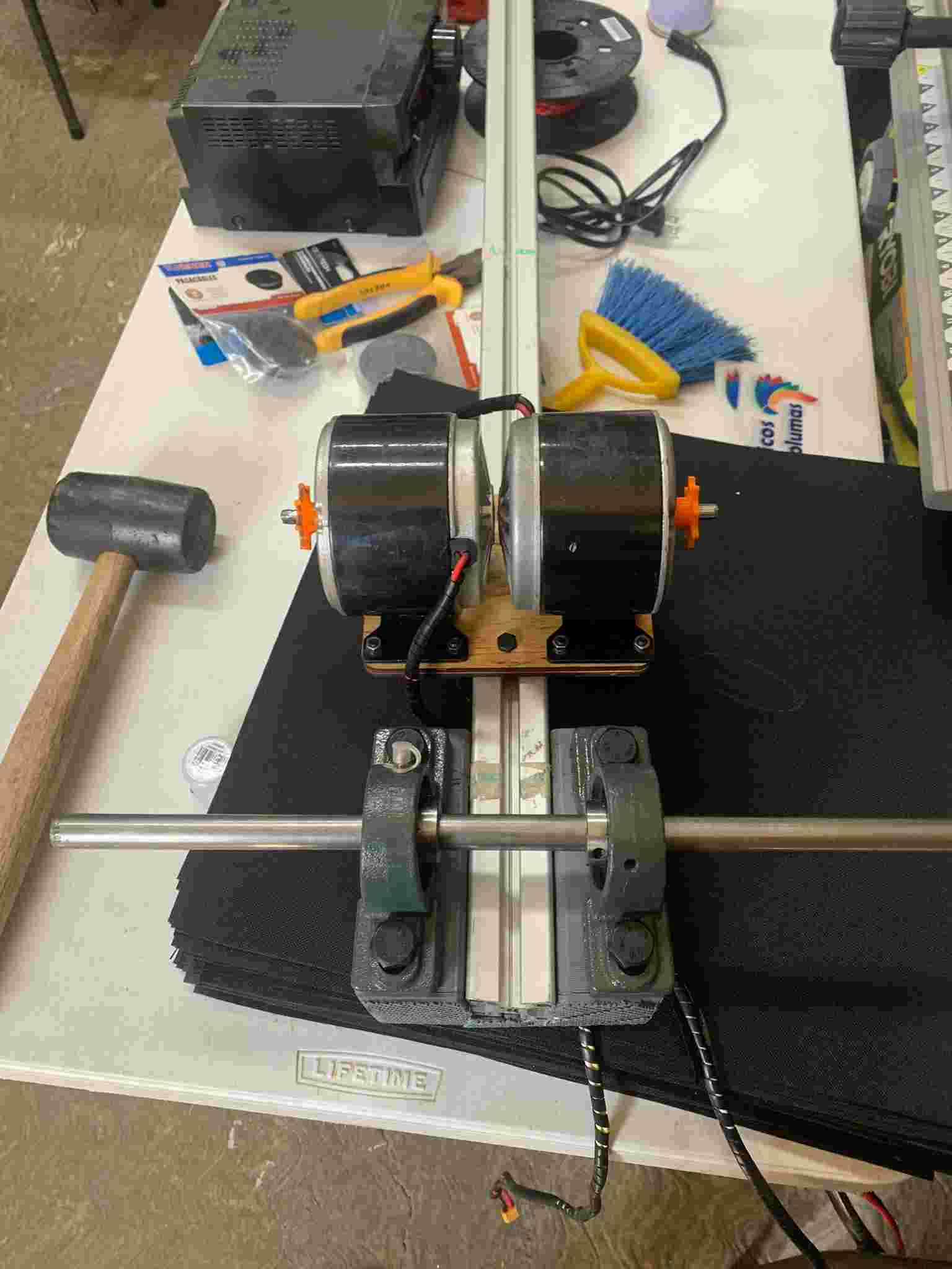
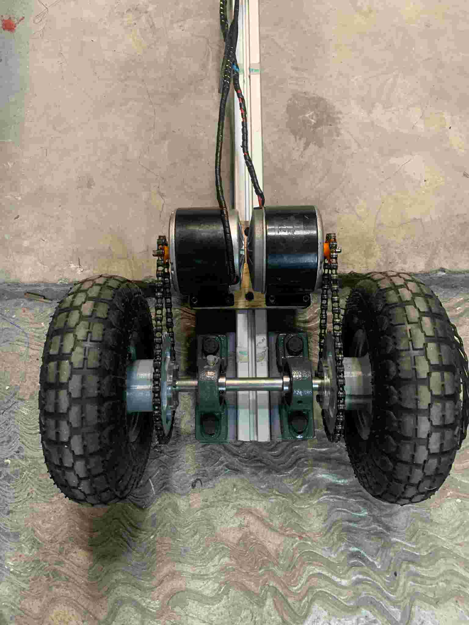
I greased everything to reduce noise and prevent wear and tear of the mechanical parts, and then tested the mechanism with an H-Bridge module (shown in the Electronics section) and a custom accelerator (shown in the Drivetrain section). You can watch the accomplished powertrain in action in the following video:
This mechanism worked correctly, and had enough torque to allow the scooter to break static friction and start moving on its own, nevertheless, some things had to be improved again in order to make the design more durable:
- The 3D printed block wasn't strong enough to hold the expected user's weight.
- The wheels are not yet fixed to the axis, in a way they can't slide out of it.
- It would be more difficult to mount dual brakes on the rear wheels (as the original plan).
To solve these issues I removed the 3D printed block and fixed the rowlocks directly using the same M12x80 screws to the previously assembled chassis (shown here)
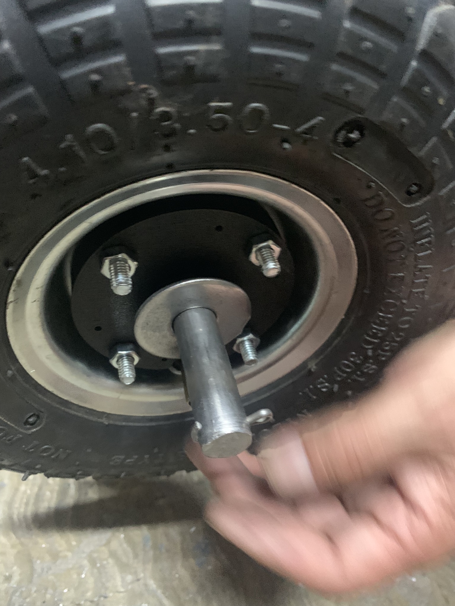
To prevent the wheels from slipping outwards over the axle and as the original plan of rear mounted brakes was discarded, I designed another set of pieces that would hold the wheel to the axle and allow for a washer and a pin to be placed, in order to fix the wheels to their horizontal position. The second piece as intended as a decorative cover for the washer and pin assembly, allowing also for the air valve on the wheels to be easily accesible.


The pin assembly is done like shown below:
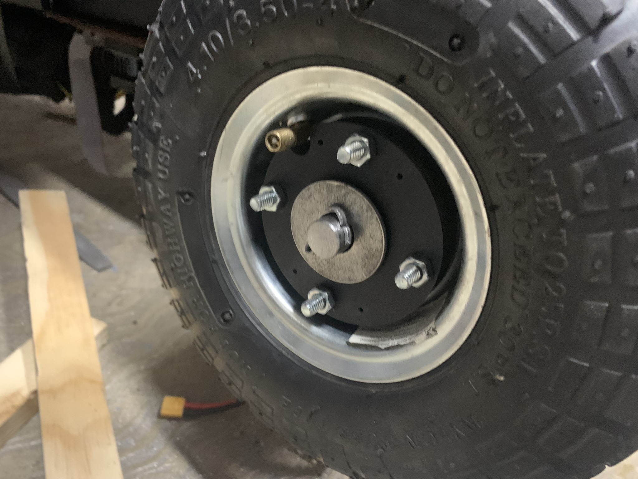

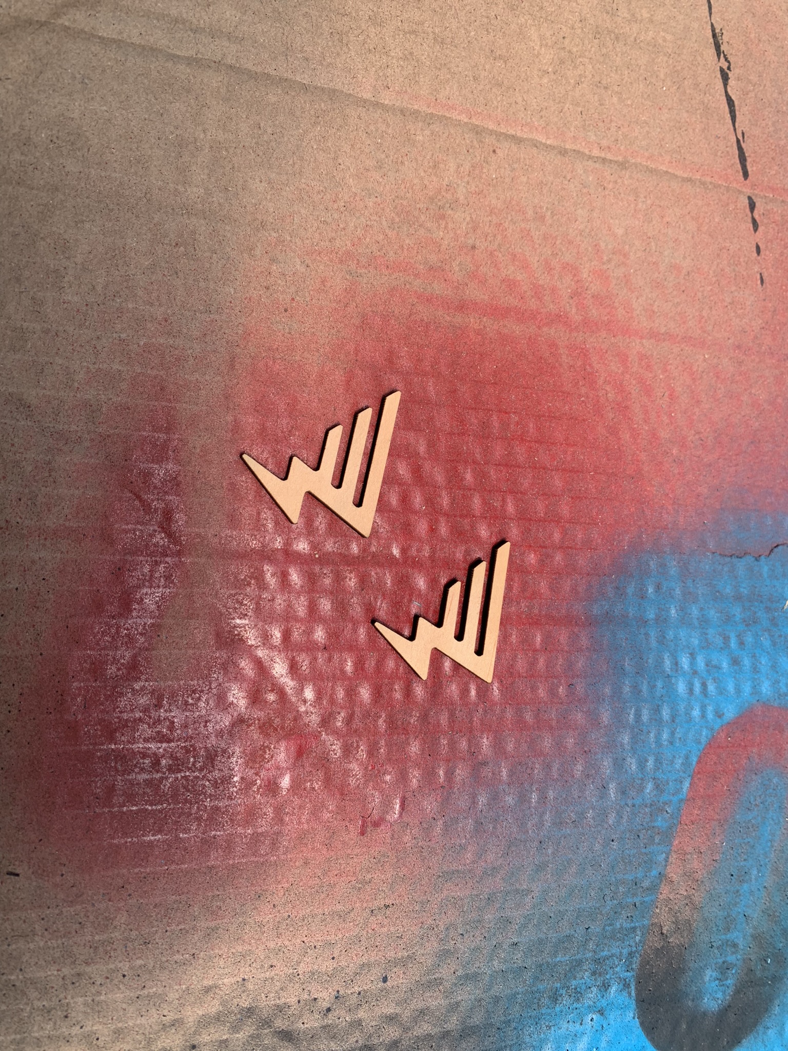
After everything has been set in place, we can add a decorative campusROVER logo onto the wheel covers. This logo is laser cutted from 3mm MDF and then glued onto the covers.


This is it for the powertrain design! See next page (Drivetrain Assembly)
Download all final proyect assets here!