Maybe I celebrated too early...
A new beginn-failure
In the world of embedded systems and electronics, input devices are how a system can sense the environment, user input, or any other external parameter. Here are various types of input devices you might consider for different projects:
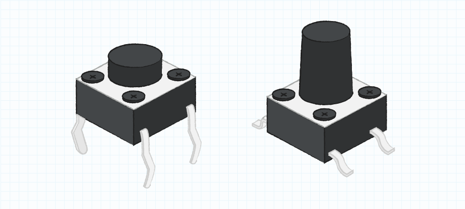
- Switches and Buttons:
- Tactile Switches: The most basic form of input, used for actions like reset or mode selection.
- DIP Switches: Allow for multiple on-off settings and are often used for configuration settings.
- Rotary Encoders: Provide input through rotation, often with detents to allow precise control over values.
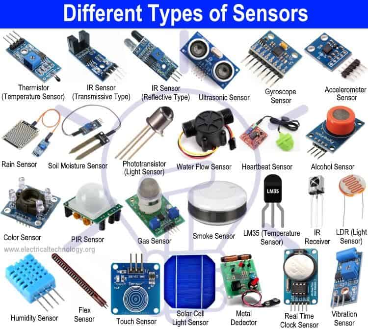
- Sensors:
- Temperature Sensors: Can range from simple thermistors to sophisticated digital sensors like the DS18B20.
- Pressure Sensors: Useful for detecting force or weight; some can measure environmental pressure for altitude.
- Humidity Sensors: Measure moisture in the air, with common types like the DHT11 or DHT22.
- Light Sensors: Photocells or photodiodes that change resistance or voltage in response to light intensity.
- Proximity Sensors: Detect the presence or distance of objects, often using ultrasonic or infrared technology.
- Motion Sensors: PIR sensors detect movement within an environment, commonly used in security systems.
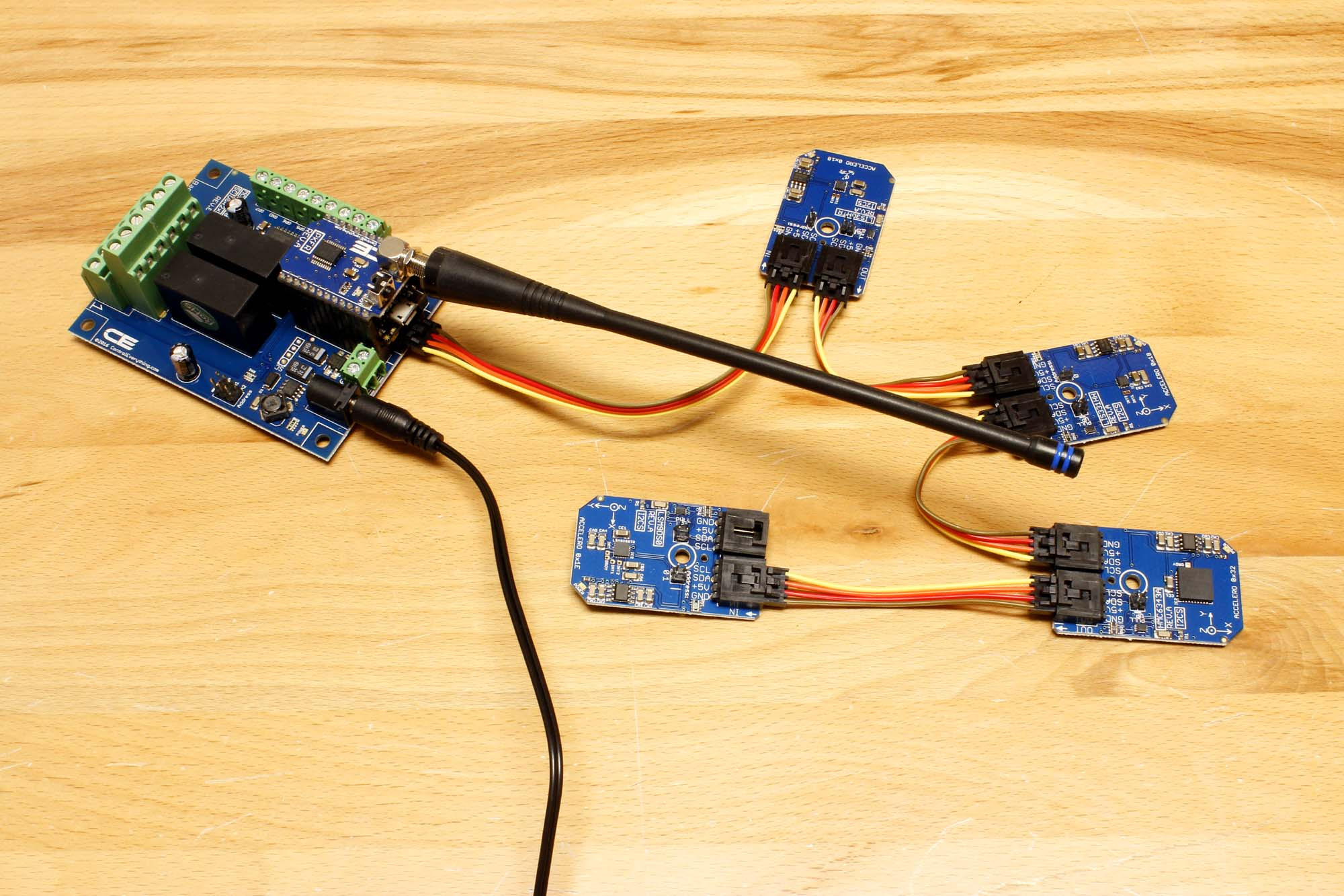
- Positional Devices:
- Potentiometers: Analog devices that provide a variable resistance, useful for dial controls.
- Accelerometers: Measure acceleration and can deduce orientation or movement.
- Gyroscope Sensors: Detect rotational movement and are key in balancing or navigation applications.
- Magnetic Sensors (Hall Effect, Magnetometer): Detect magnetic fields and can be used for position or rotation detection.
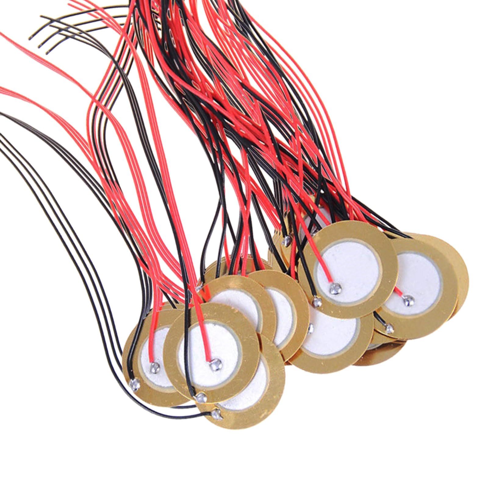
- Audio Devices:
- Microphones: Convert sound into an electrical signal, either as an analog output or with digital interfaces like I2S.
- Piezoelectric Elements: Can be used both as a buzzer for output and a vibration sensor for input.
- Environmental Sensors:
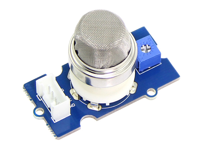
- Gas Sensors: Detect various gases like carbon monoxide, methane, or air quality indicators.
- Particle Sensors: Measure particulate matter in the air, important for air quality monitoring.
- Advanced Input Devices:
- Touch Screens: Provide both output (display) and input (touch) for interactive projects.
- Cameras: Capture images or video for processing or surveillance.
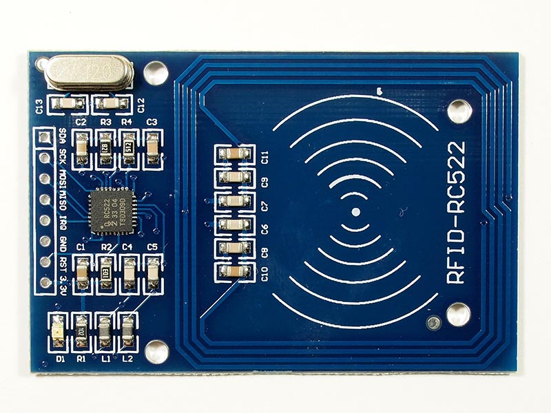
- RFID Readers: Read RFID tags for identification or tracking purposes.
- Barcode Scanners: Input data by scanning barcodes, commonly used in retail and inventory management.
- Custom Inputs:
- Soft Potentiometers: Flexible, touch-sensitive strips that can be used in wearable tech.
- Flex Sensors: Change resistance when bent, useful in gloves or other wearables to detect finger movement.
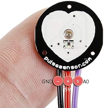
- Bio Sensors: Monitor physiological data like heart rate, muscle movement, or brain activity.
Each input device offers unique opportunities and challenges. Selection typically depends on the specific requirements of your project, such as the type of data you need to collect, the environment in which the device will operate, and the level of precision required.
Integrating these devices with a microcontroller involves both hardware interface—wiring them correctly to the board—and software interface—programming the board to read and interpret the signals from the input devices.
How To Program an Input Device
In order to program an input device, the user will need to harness the Serial library in the Arduino IDE, which is indispensable for facilitating communication. This library enables the user to send and receive data over the serial ports, TX and RX. It is recommended to set the baud rate for serial communication to 9600, but the library's versatility allows them to alter this speed to suit the unique demands of their application.
For the acquisition of analog signals, turn to the analogRead() function. This function is integral; it takes a voltage reading from an analog input pin and translates it into a digital representation. The conversion relies on the Arduino's reference voltage, standardly 5V, meaning a 5V signal yields a digital reading of 1023 due to the Arduino's 10-bit ADC that maps 0-5V into integer values from 0 to 1023. Therefore, a voltage of 2.5V will result in a reading of approximately 512, signifying the midpoint of the signal's potential range.
By implementing this method, the user can precisely decode and respond to a broad spectrum of analog signals from various sensors or input apparatuses, transmuting them into a digital format that the microcontroller is capable of interpreting and processing. This setup empowers the user to discern the intricacies and fluctuations of the input devices, crucial for imparting their project with exact and dynamic control.
You can see more info in this week's Group Assignment.
Here comes the problems
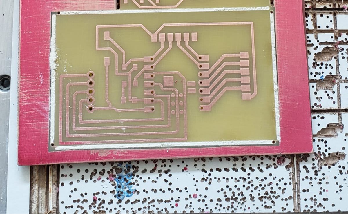
My confidence was high when I started out, based on the solid design groundwork I had laid for my PCB from the previous week. The design was straightforward: it was essentially a breakout board that would funnel all the signals from the Xiao ESP32-C3 module into accessible pins.
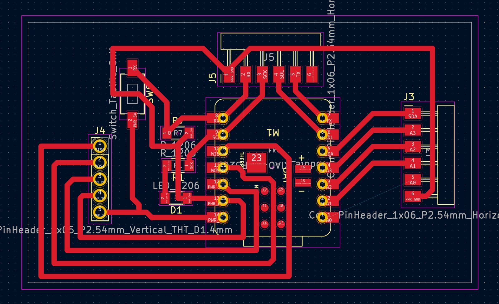
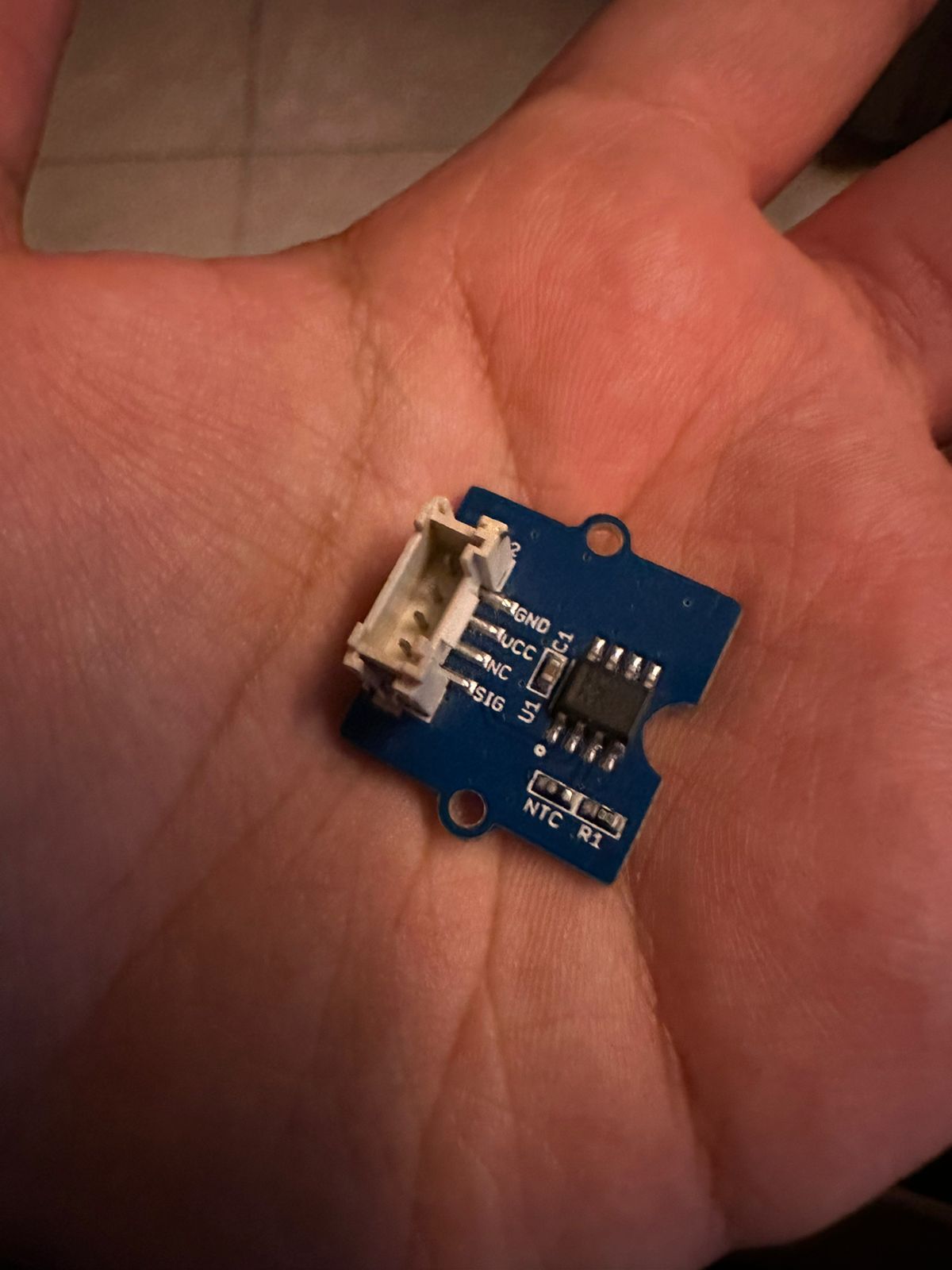
My plan was simple—take these signals and directly connect them to the temperature sensor I had procured. This sensor, like many, had the standard pinout: GND, VCC, NC (not connected), and SIG (signal). The idea was that once connected, the Xiao would power the sensor and be able to read the temperature data from the SIG pin.
I had meticulously ensured that my PCB design accounted for the necessary connections. All I needed to do was to solder the Xiao onto my PCB and use jumper wires to connect the PCB to the sensor. With the ground and power pins providing the necessary supply to the sensor, and the signal pin ready to transmit data, it seemed like a foolproof plan.
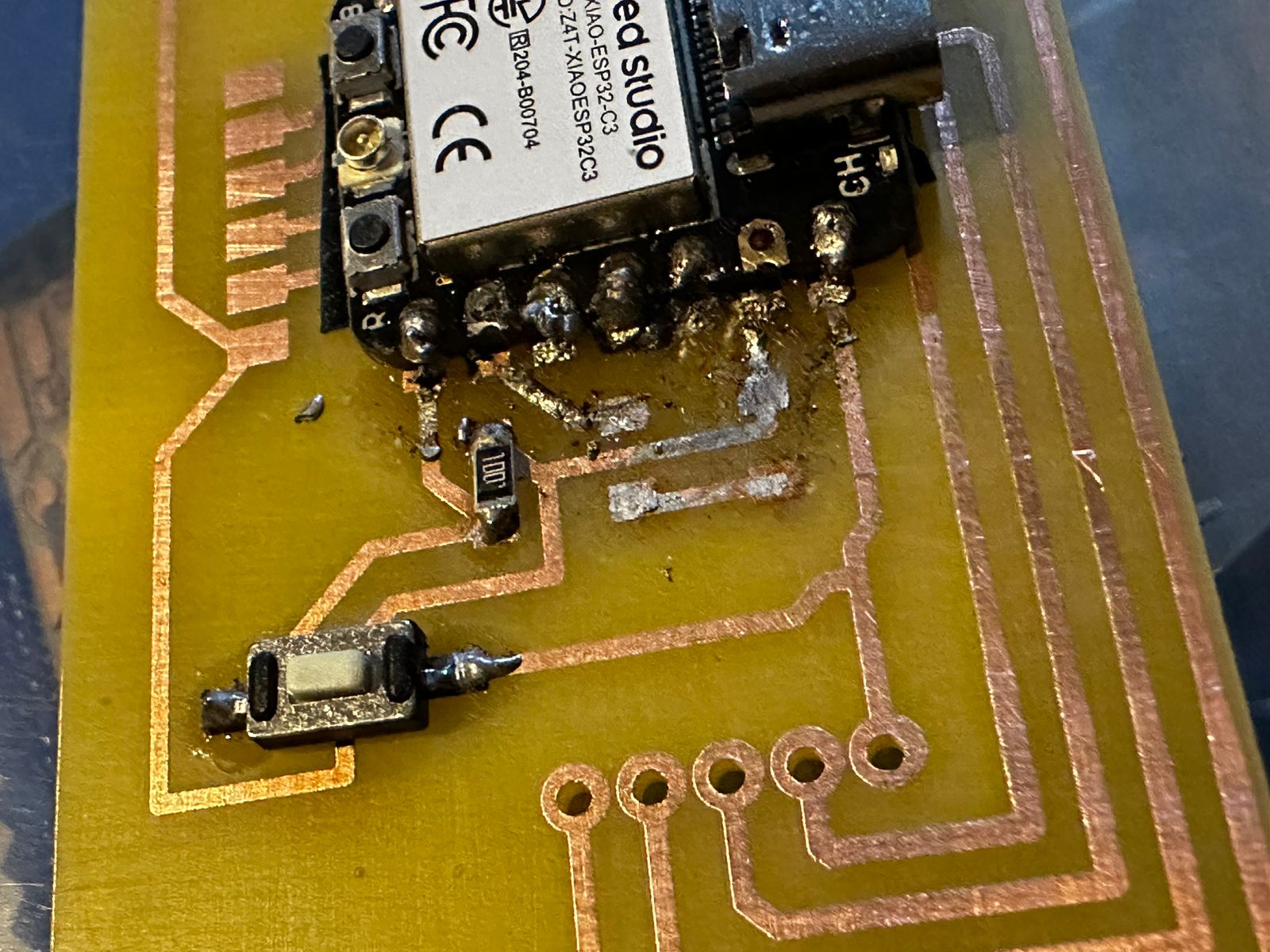
However, the soldering process turned out to be my undoing. Despite my prior experience, the subpar solder I had bought led to a frustrating mess. The solder spread where it wasn't supposed to, creating shorts and risking damage to the Xiao module itself. The experience was disheartening, and for a moment, I feared that my entire project was compromised.
TRIGGER WARNING
With this mess it was clear that I wasn't able to use this board anymore and I couldn't finish the assignment on time. After the soldering debacle, I had to learn to desolder quickly. Thankfully a friend of mine taught me what materials I should use to desolder quickly and efficiently without causing more damage that was already done. Here are the list of materials I used to desolder:
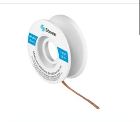
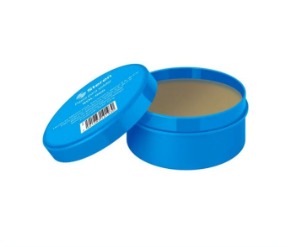

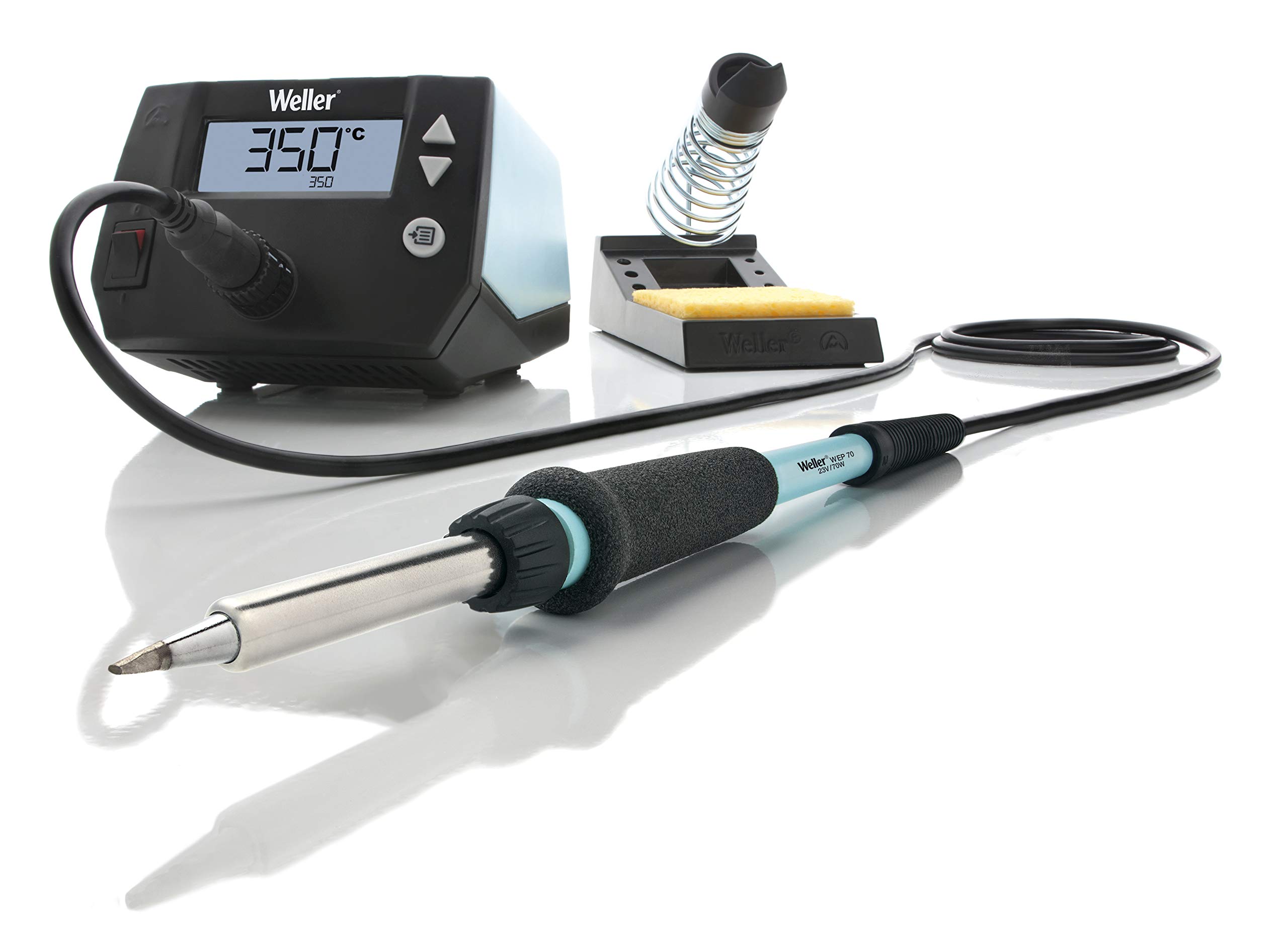
Using desoldering mesh that was submerged with Flux and applying heat with the Heat Gun and the Weller, I painstakingly removed the excess solder from the board. This process was new to me, and while challenging, it was also a valuable skill to acquire. Following this, I understood the importance of solder paste and its role in facilitating proper soldering.
However, I was able to save my, quite expensive, Xiao ESP32C3!
.jpeg)
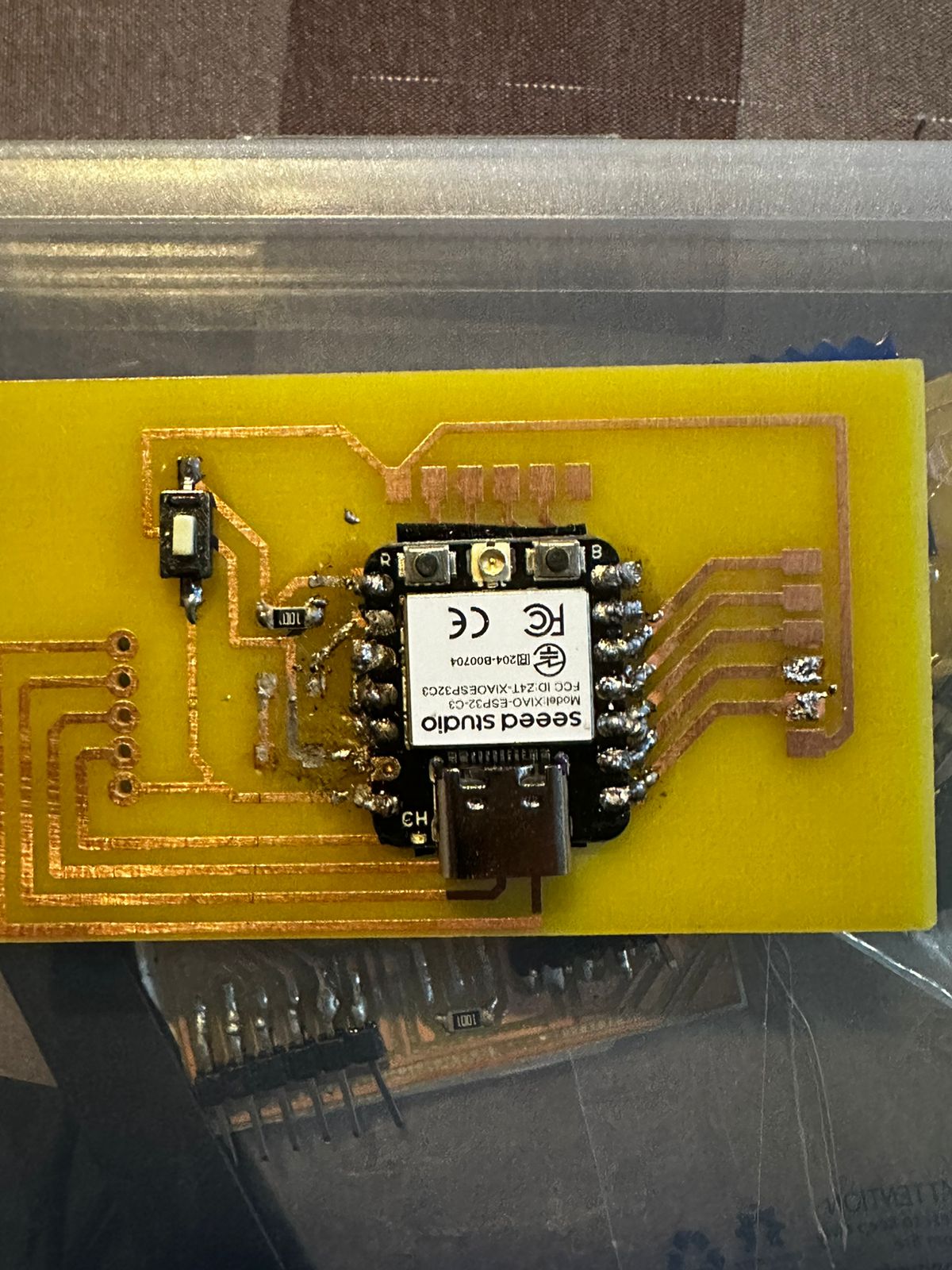
And here is what the board was like after cleaning everything up...
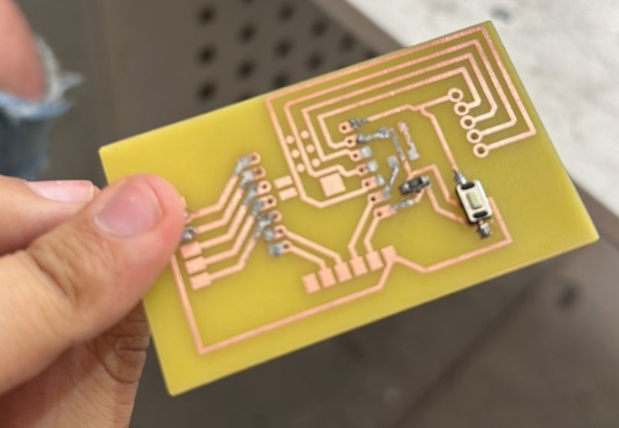
As you can see, it's beyond saving... there is solder everywhere!
Reflecting on this journey, I realized that my initial confidence, while well-founded, had perhaps made me overlook the finer details of soldering quality and material choice. The lessons learned were clear: patience is just as important as confidence, and the right materials are crucial for success. As I prepare to reattempt soldering my PCB, I'm more cautious and informed, ready to proceed with the wisdom that setbacks are often the best teachers. I also realized that I can make my PCB safer by adding female pins into where the XIAO is supposed to go, this way, if I mess up, it won't damage the XIAO and I can change it easily.
Conclusion:
In conclusion, my journey from a confidently designed PCB to facing the trials of poor-quality solder has been both humbling and instructive. What began as a smooth path paved with clear intentions—to seamlessly integrate a temperature sensor with my Xiao module—became a testament to the unpredictability of the physical world and the craft of electronics. My ordeal with the solder taught me the irreplaceable value of quality materials and the importance of meticulousness in the soldering process.
The desoldering mesh, an unanticipated yet crucial tool, helped me salvage my components and, more importantly, served as a practical lesson in electronics repair. This experience, frustrating as it was, enriched my understanding of the assembly process and reaffirmed the notion that behind every successful project is a series of lessons learned through perseverance and adaptation.
As I look ahead, I am equipped not just with a better-soldered PCB but with a deeper appreciation for the art and science of electronics—a field where even the smallest details can make the largest difference.
Update: 05/20/2024
After fixing the PCB Design I decided to go back and work on input devices.
Transition from XIAO ESP32C3 to XIAO ESP32S3:During the development process, I transitioned from using the XIAO ESP32C3 to the XIAO ESP32S3. This change provided additional capabilities and better suited the project's needs, particularly with the touch-sensitive input functionality. The XIAO ESP32S3 offered enhanced performance and reliability, which was crucial for the accurate detection and handling of touch inputs in my project.
Input DevicesIn my project, I utilized the XIAO ESP32S3 touch pins to detect input signals. The XIAO ESP32S3 features touch-sensitive pins that can detect capacitance changes when touched by a finger. This functionality allows for innovative ways to capture user inputs without mechanical buttons.
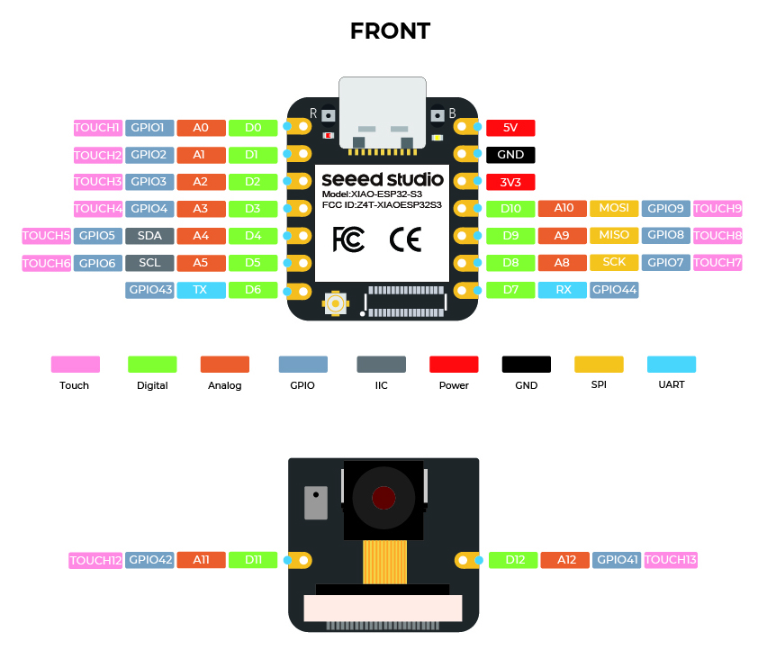
How the XIAO ESP32S3 Touch Pins Work:The touch pins on the XIAO ESP32S3 work by detecting changes in capacitance. When a finger or another conductive object comes near or touches the pin, it alters the electrical field, which the microcontroller can sense. This change is converted into a digital signal that the microcontroller processes to determine whether a touch has occurred.
Below is an image that shows the touch pin configuration of the XIAO ESP32S3:
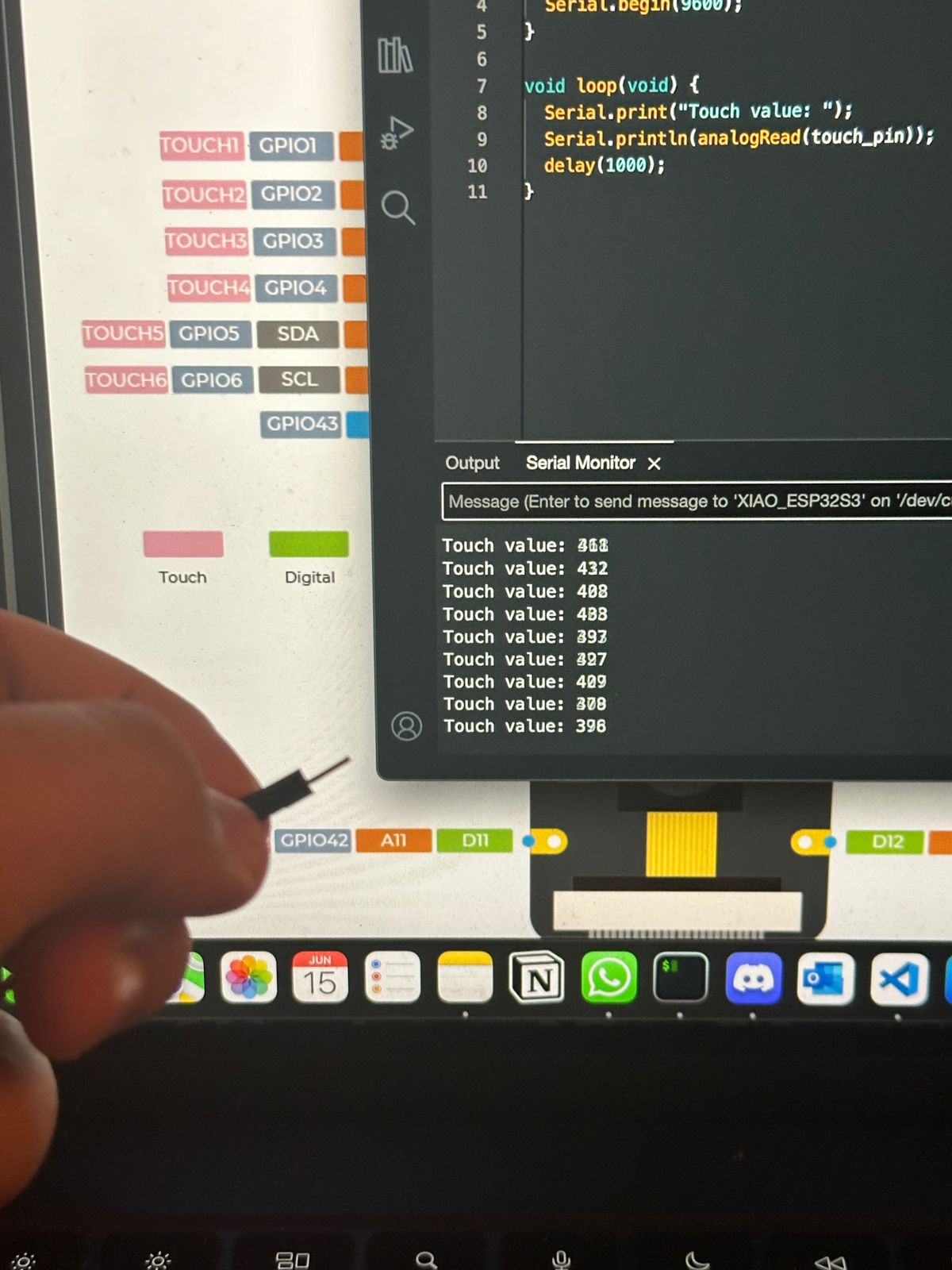
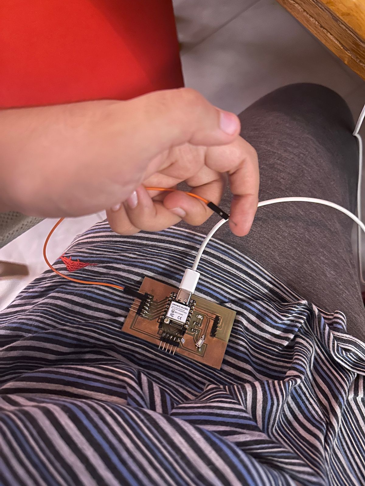
Detecting Signals with Finger Touch
To explore how effectively the touch pins could detect signals, I started by simply passing my finger over the pins. This method demonstrated that the pins could reliably register touch inputs. Here is the basic code I used to test this:
const int touch_pin = A5;

void setup(void) {
	Serial.begin(9600);
}

void loop(void) {
	Serial.print("Touch value: ");
	Serial.println(analogRead(touch_pin));
	delay(1000);
}
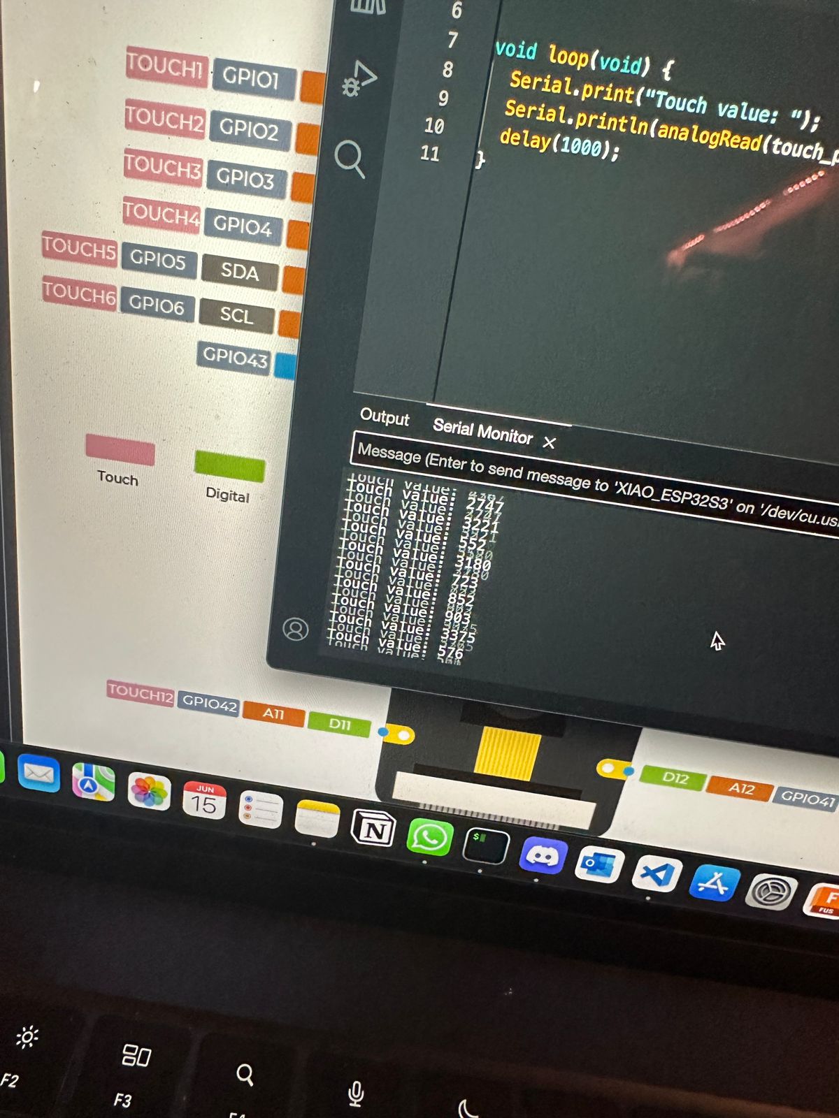
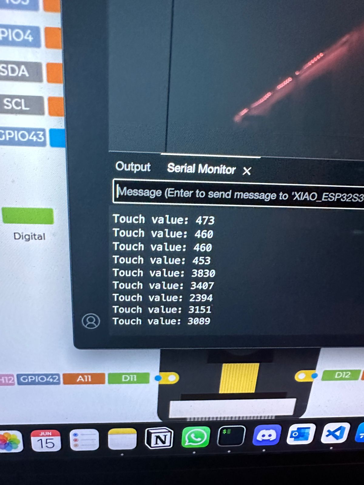
However, I encountered some errors with faulty detection. To resolve this, I initialized the serial communication at a baud rate of 115200, which improved the accuracy of the touch readings.
XIAO ESP32S3 configuration:
Serial Monitor result:
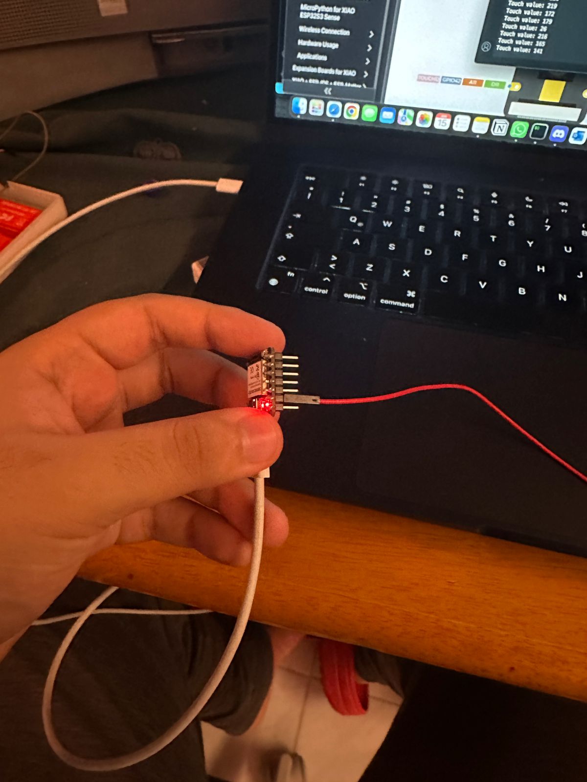
Using a Jumper to Detect Finger Touch
To further test the touch detection capabilities, I used a jumper cable. By holding the jumper and touching it to the pin, I could see if the touch detection was consistent. Indeed, the jumper effectively detected my touch, confirming the touch pins' reliability.
Testing with PCB Pins
Following the jumper test, I tried the same method with PCB pins. By touching the jumper connected to the PCB pins directly, the touch inputs were registered successfully, indicating that the PCB pins could serve as touch-sensitive inputs.
Integrating Touch Detection into the SNES Controller
Building on the tests with touch detection, I decided to integrate this capability into an SNES controller for the GameShine project. The goal was to create a more ergonomic design, reduce space usage, and minimize copper consumption, thereby giving the project a more native and refined feel.
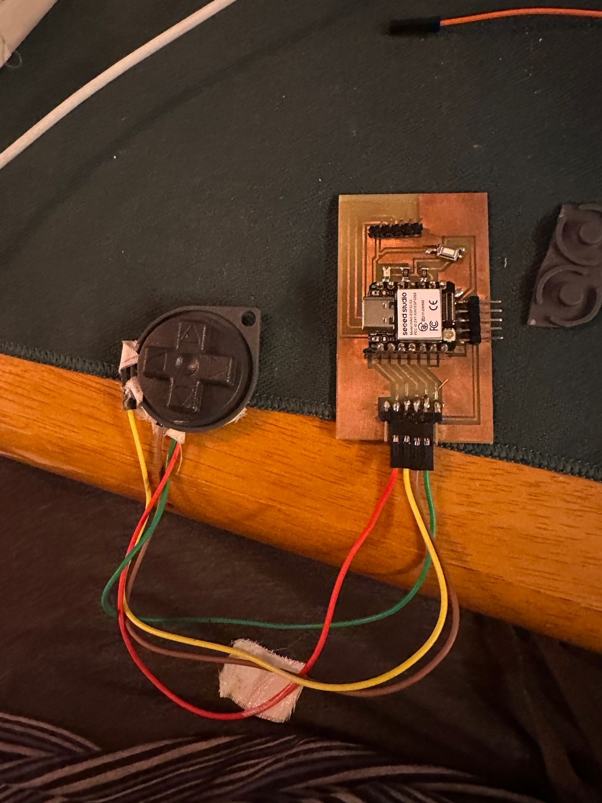
Implementation ProcessTo achieve this, I inserted a jumper cable through the rubber pad of the SNES controller.
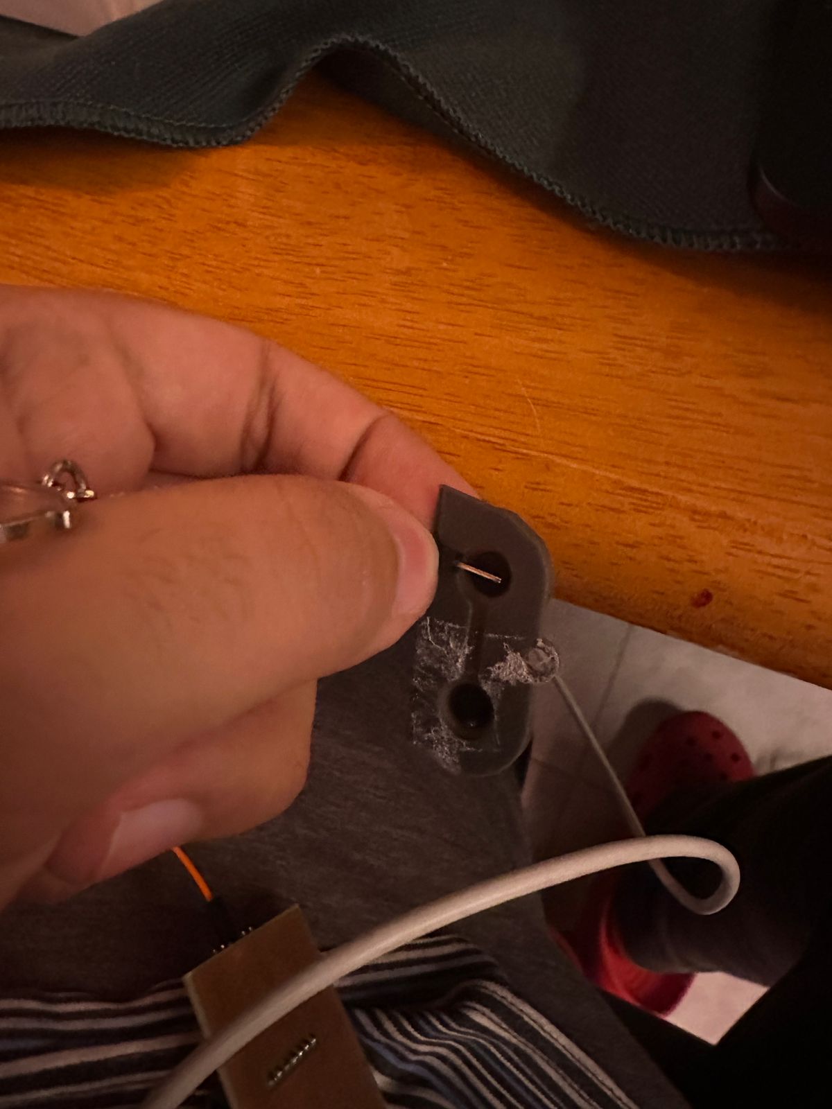
The idea was that when a button was pressed, it would send a signal through the tape of the pad into the jumper, registering as an input. This method aimed to leverage the conductive properties of the rubber pad and the jumper cable to detect button presses without traditional mechanical switches.
.jpeg)
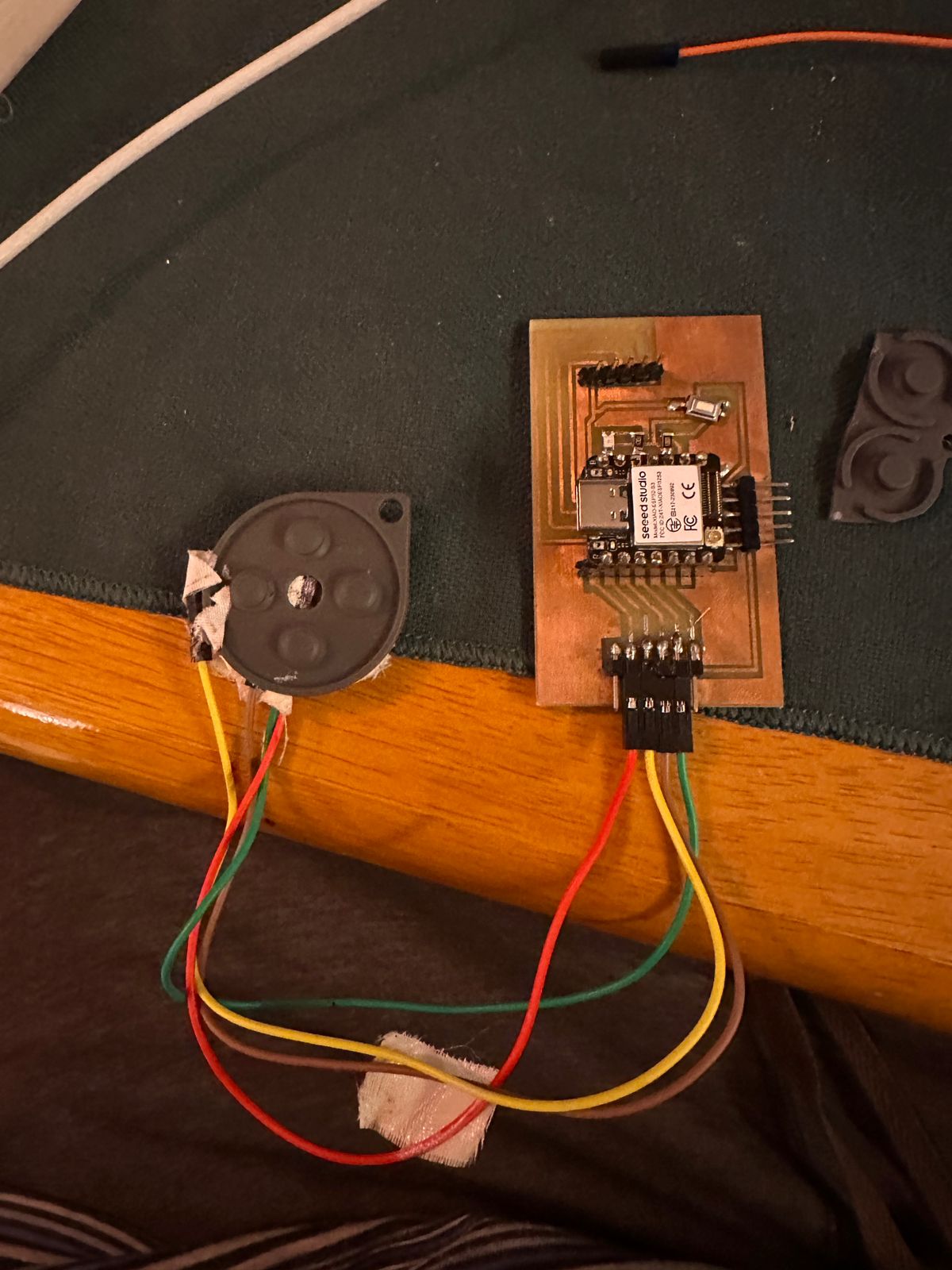
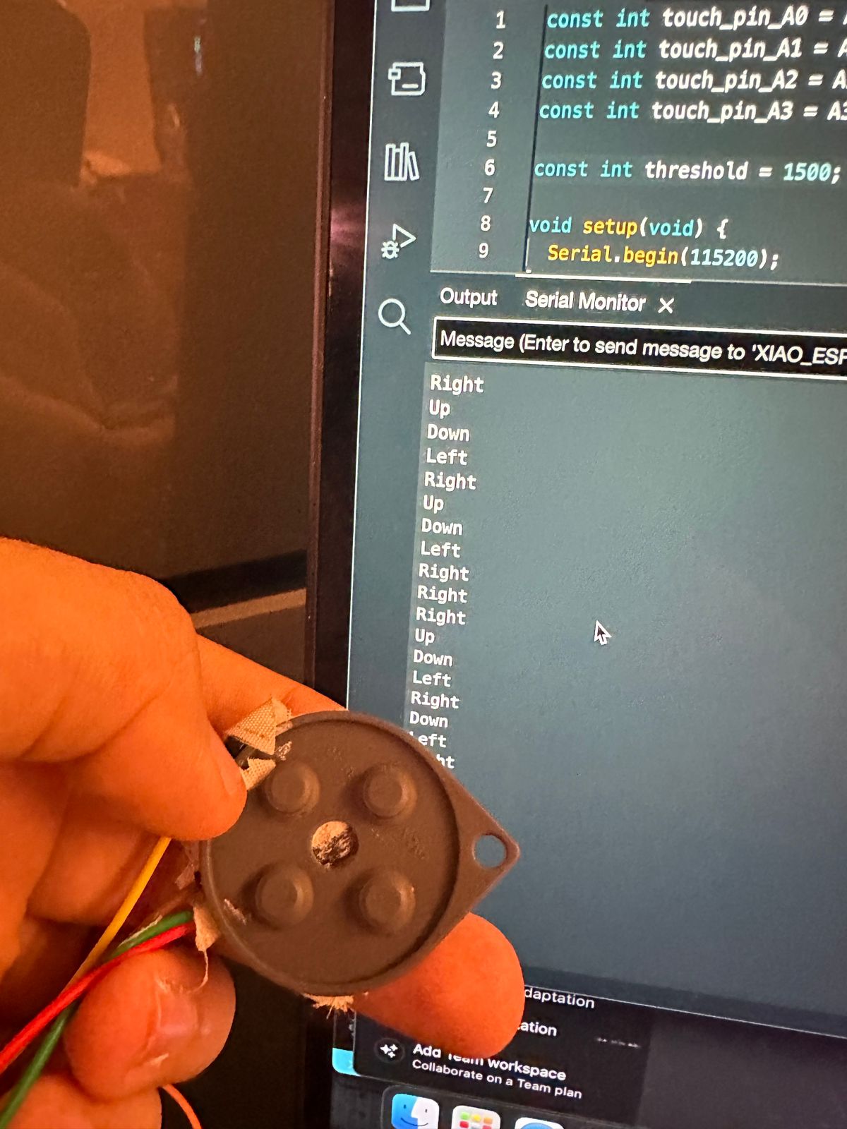
With this in mind, I decided to connect four jumper cables into the rubber D-pad, each corresponding to a different direction. Thus, A0 was for up, A1 for down, A2 for left, and A3 for right.
Here is the code I used to test the up, down, left, and right buttons of the SNES controller:
const int touch_pin_A0 = A0;
const int touch_pin_A1 = A1;
const int touch_pin_A2 = A2;
const int touch_pin_A3 = A3;

const int threshold = 1000;  // Set a higher threshold to detect valid inputs from the conductive tape

void setup(void) {
Serial.begin(115200);
}

void loop(void) {
int value_A0 = analogRead(touch_pin_A0);
int value_A1 = analogRead(touch_pin_A1);
int value_A2 = analogRead(touch_pin_A2);
int value_A3 = analogRead(touch_pin_A3);

if (value_A0 > threshold) {
	Serial.println("Up");
}
if (value_A1 > threshold) {
	Serial.println("Down");
}
if (value_A2 > threshold) {
	Serial.println("Left");
}
if (value_A3 > threshold) {
	Serial.println("Right");
}

delay(1000);
}
This code reads values from multiple touch pins and prints the corresponding button press ("Up", "Down", "Left", "Right") to the serial monitor if the value exceeds the threshold.
Serial Monitor:
Next I did the same test but now with the Dpad being placed in the rubber pad.
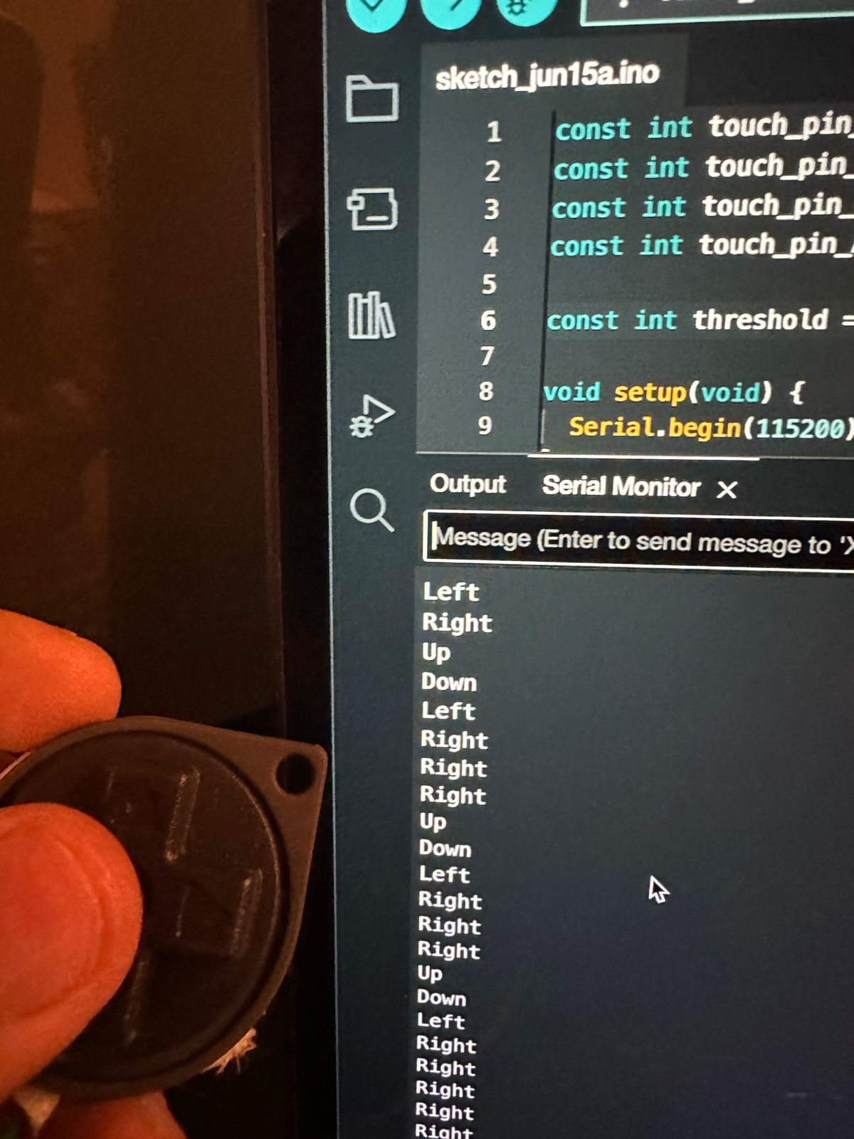
Addressing Detection Issues
Initially, I faced issues with the touch value being reduced because the conductive tape from the rubber pad did not produce the same value as a direct finger touch. The capacitance change caused by the rubber pad and tape was significantly lower than that of a human finger. To resolve this, I adjusted the touch detection threshold to ensure that it accurately detected valid inputs. Setting a higher threshold helped filter out noise and register genuine button presses reliably.
Benefits of This ApproachBy applying this touch detection method, I was able to convert the button presses of the SNES controller into touch inputs for the XIAO ESP32S3. This integration brought several advantages:
- Ergonomics: The touch-sensitive buttons provided a smoother and more comfortable user interaction, enhancing the overall gaming experience.
- Space Efficiency: Eliminating mechanical switches reduced the internal space required for the controller's components, allowing for a more compact design.
- Reduced Copper Consumption: By using touch detection instead of traditional circuitry, I minimized the amount of copper used in the design, aligning with sustainable design principles.
- Native Feel: The touch-sensitive buttons gave the GameShine project a more modern and intuitive interface, making it feel more native and advanced.
The same logic applied to the directional buttons was extended to the A and B buttons of the SNES controller. Each button was equipped with a jumper cable and connected to a touch pin on the XIAO ESP32S3. By maintaining a consistent threshold across all buttons, I ensured uniform sensitivity and reliable detection for all inputs.
Conclusion
Integrating touch detection into the SNES controller for the GameShine project was a transformative step that leveraged the advanced capabilities of the XIAO ESP32S3. By connecting jumper cables through the rubber D-pad and other buttons, I was able to convert traditional mechanical inputs into modern, capacitive touch inputs. This approach significantly enhanced the ergonomics, reduced the internal space requirements, and minimized copper consumption, aligning with sustainable design principles.
Despite initial challenges with faulty touch detection and lower capacitance values from the conductive tape, adjusting the detection threshold provided a reliable solution. This innovation resulted in a smoother, more intuitive user experience, giving the GameShine project a native and advanced interface.
The successful implementation of this touch detection method not only improved the functionality and design of the SNES controller but also demonstrated the potential for future enhancements in electronic projects. By overcoming these challenges and integrating touch technology, the GameShine project now stands as a testament to creativity, adaptability, and technical prowess in modern electronics.
The Files:
Below you can find the download links for all of the files from this week.