Week 9: Input Devices
Overview
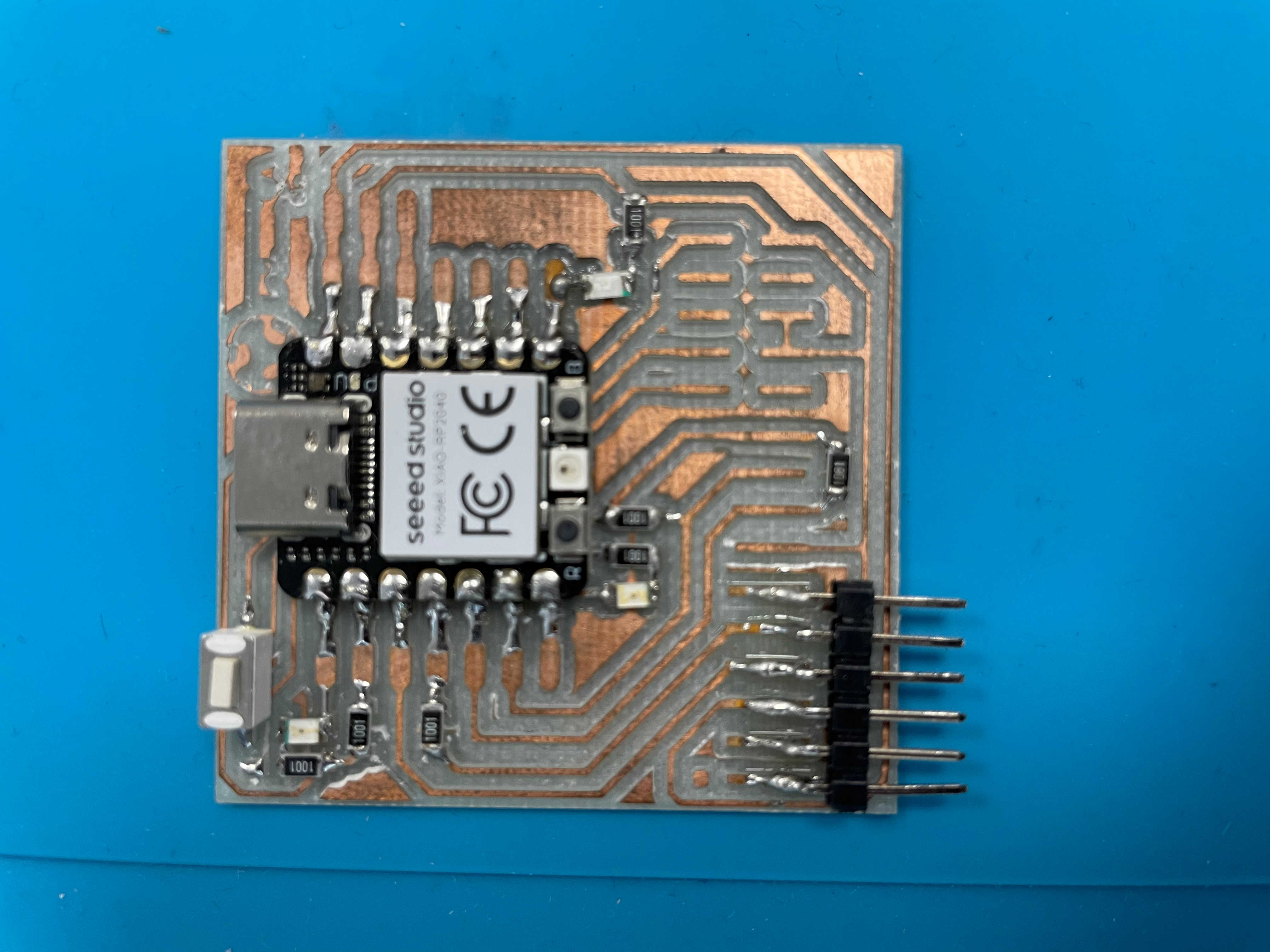
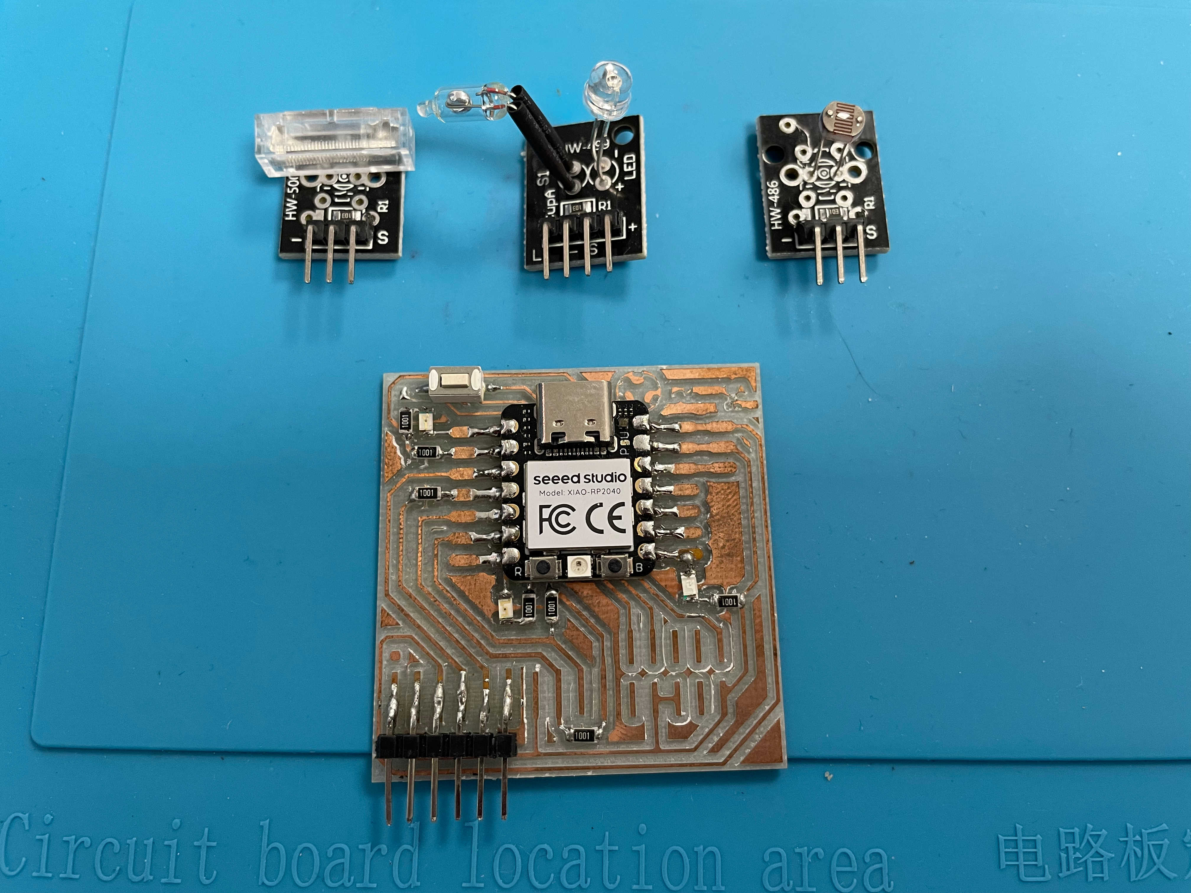
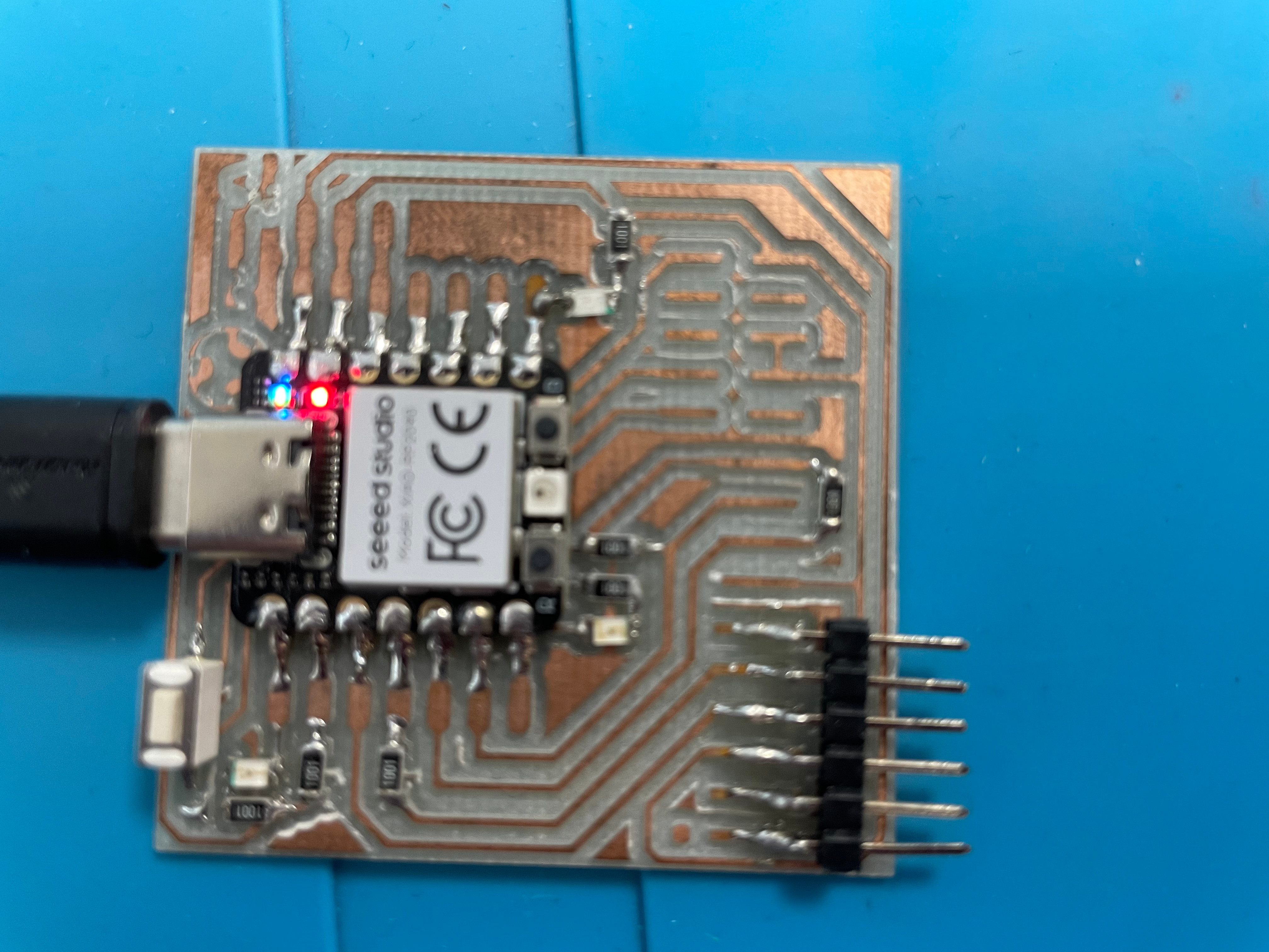
This week, I focused on testing and documenting input devices using the Seeed Studio XIAO RP2040 microcontroller mounted on a custom board that I designed and milled in a previous assignment. The board includes breakout headers for all I/O pins, a pushbutton, and three indicator LEDs: blue, orange, and red.
Considering the requirements of this assignment, I aimed to:
- Explore different types of input sensors (both digital and analog)
- Interface them with the XIAO RP2040 using the Arduino IDE and MicroPython
- Use the built-in components of my custom board for visual feedback
- Visualize sensor data using the Arduino Serial Plotter
For this assignment, I tested:
- Photoresistor (KY-018) – analog light intensity sensor
- Mercury Tilt Sensor (KY-027) – digital tilt/vibration sensor
- Impact Sensor (KY-031) – digital knock sensor
- Pushbutton – tested for digital input and interaction with LEDs
- KY-037 Sound Sensor
Checklist
Group Assignment: Input Devices
For more details, visit the group assignment page: Group Assignment - Week 9
Findings
This week, as a group, we got hands-on with different input devices and tested how they behave under real conditions. I tested individually a few sensors, including a Photoresistor (KY-018) for light intensity, a Mercury Tilt Sensor (KY-027) for detecting tilt and vibration, an Impact Sensor (KY-031) for knock detection, and a classic Pushbutton to work with digital inputs and LED interaction.
One big thing we learned is that sensors don’t just magically give you perfect data — you usually need to calibrate them, filter the signals, and sometimes rethink how you're connecting them to your microcontroller (hello, pull-up and pull-down resistors!). We also noticed that not all sensors fit all projects: depending on what you need (like speed, precision, or energy efficiency), you might prefer one sensor over another.
Why This Week Matters
Input devices are basically the "senses" of any project. Without good inputs, your system is like a robot walking blindfolded. Learning how to read the world properly through sensors is what makes interactive, reactive, and smart systems even possible. Whether it’s for a simple pushbutton or a more complex light or impact sensor, understanding inputs is a core skill for building anything awesome.
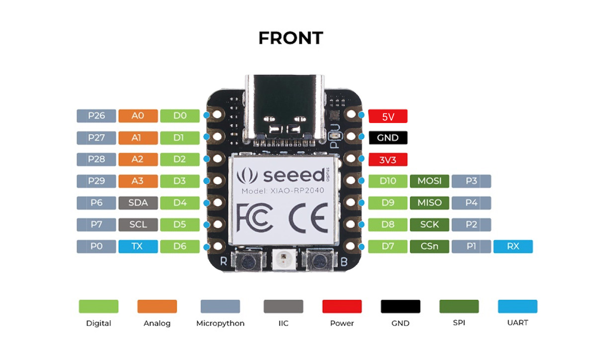
Xiao RP2040
The XIAO RP2040 is a compact microcontroller board based on the RP2040 chip. It features USB-C, 11 GPIOs, and supports multiple communication protocols, making it ideal for small embedded projects.
Technical reference and datasheet: Seeed Studio - Xiao RP2040
Custom Board with Xiao RP2040
I designed and milled a custom board in a previous assignment to serve as a base for testing sensors and output devices. The board includes labeled headers, a button, and three onboard LEDs for feedback.
Input 1: Photoresistor (KY-018)
This analog sensor detects light intensity. It outputs a voltage that varies with light exposure, which we read using an analog input pin. Data was visualized using the Serial Plotter.
Technical reference: KY-018 Photoresistor Module
    const int ldrPin = A2;  // Analog pin where the LDR is connected
    int lightValue;         // Variable to store the LDR reading

    void setup() {
        Serial.begin(9600);             // Start serial communication
        pinMode(ldrPin, INPUT);         // Set LDR pin as input
    }

    void loop() {
        // Read analog value from the LDR (range: 0 to 1023)
        lightValue = analogRead(ldrPin);

        // Print only the value, so it's compatible with the Serial Plotter
        Serial.println(lightValue);

        delay(50);  // Short delay to make the plot smoother
    }
The photoresistor outputs an analog voltage that varies with the amount of light it receives. In the code, the analog value is read from pin A2 using analogRead(). The result is printed to the Serial Monitor, and visualized in the Arduino Serial Plotter. Brighter light results in lower values, and darkness increases the reading.
Input 2: Mercury Tilt Sensor (KY-027)
This sensor uses a small mercury capsule to detect tilt or vibration. Different LED patterns were triggered based on the number of spikes detected over time.
Note: This sensor contains mercury, which is considered toxic. For safety, modern alternatives like accelerometers or solid-state tilt switches are recommended.
Technical reference: KY-027 Magic Light Cup Module
    const int sensorLED = D3;     // Onboard LED of the KY-027 module
    const int sensorPin = D2;     // Digital output from the KY-027 sensor
    int sensorValue;
    int previousValue = LOW;
    int triggerCount = 0;

    void setup() {
        Serial.begin(9600);
        pinMode(sensorLED, OUTPUT);
        pinMode(sensorPin, INPUT);
    }

    void loop() {
        sensorValue = digitalRead(sensorPin);

        // Detect tilt or vibration (LOW → HIGH)
        if (sensorValue == HIGH && previousValue == LOW) {
        triggerCount++;
        }

        previousValue = sensorValue;

        // Control the onboard LED
        digitalWrite(sensorLED, sensorValue);

        // Print values in a format suitable for the Serial Plotter
        // Format: sensorValuetriggerCount
        Serial.print(sensorValue);
        Serial.print("\t");
        Serial.println(triggerCount);

        delay(100);
    }
This code monitors tilt or vibration activity using the KY-027 sensor connected to a digital input. Each time a HIGH signal is detected, a timestamp is recorded. Over a moving time window (1.5 seconds), the code counts how many spikes occurred. Based on the count, it activates one or more LEDs with different flashing patterns to indicate low, moderate, or continuous vibration. This approach simulates basic signal processing with visual feedback.
Input 3: Impact Sensor (KY-031)
This digital sensor detects physical impacts or knocks. The LED responds with a flash on impact and data is plotted in the Serial Plotter.
Technical reference: KY-031 Knock Sensor Module
    const int sensorPin = D2;   // KY-031
    const int ledBlue   = D7;
    const int ledOrange = D6;
    const int ledRed    = D0;

    const int maxSpikes = 10;
    unsigned long spikeTimes[maxSpikes];
    int spikeIndex = 0;

    unsigned long lastRedToggle = 0;
    bool redState = false;

    void setup() {
        Serial.begin(9600);
        pinMode(sensorPin, INPUT);
        pinMode(ledBlue, OUTPUT);
        pinMode(ledOrange, OUTPUT);
        pinMode(ledRed, OUTPUT);

        digitalWrite(ledBlue, LOW);
        digitalWrite(ledOrange, LOW);
        digitalWrite(ledRed, LOW);
    }

    void loop() {
        int hit = digitalRead(sensorPin);
        unsigned long now = millis();

        // Record spikes
        if (hit == HIGH) {
            spikeTimes[spikeIndex] = now;
            spikeIndex = (spikeIndex + 1) % maxSpikes;
            delay(50);  // debounce
    }

    // Count recent spikes
    int spikeCount = 0;
    for (int i = 0; i < maxSpikes; i++) {
        if (now - spikeTimes[i] < 1500) {
        spikeCount++;
        }
    }

    // RED FLASH MODE
    if (spikeCount >= 4) {
        digitalWrite(ledBlue, HIGH);
        digitalWrite(ledOrange, HIGH);

        // Flash red LED fast (toggle every 100 ms)
        if (now - lastRedToggle > 100) {
        redState = !redState;
        digitalWrite(ledRed, redState ? HIGH : LOW);
        lastRedToggle = now;
        }

    } else {
        // Reset red LED state
        digitalWrite(ledRed, LOW);
        redState = false;

        if (spikeCount >= 2) {
        // Moderate: blue solid, orange flashing
        digitalWrite(ledBlue, HIGH);
        if ((now / 100) % 2 == 0) {
            digitalWrite(ledOrange, HIGH);
        } else {
            digitalWrite(ledOrange, LOW);
        }
        } else if (spikeCount == 1) {
        // Single spike: blue flash
        digitalWrite(ledBlue, HIGH);
        delay(100);
        digitalWrite(ledBlue, LOW);
        delay(100);
        digitalWrite(ledOrange, LOW);
        } else {
        // No activity: all off
        digitalWrite(ledBlue, LOW);
        digitalWrite(ledOrange, LOW);
        }
    }

    delay(50);
    }
The KY-031 detects physical impacts as short digital pulses. The code reads the sensor on pin D2 and sends the result to the Serial Plotter. A spike (HIGH) briefly activates the onboard or external LED. If multiple spikes occur over a short period, the LED behavior escalates accordingly. This provides both visual and plotted feedback of how often and how intensely impacts are detected.
Input 4: Pushbutton
As part of my FabAcademy assignment on input devices, this was the fourth and final experiment. The goal here was to explore a new way of working with the RP2040 by using MicroPython instead of the Arduino IDE, and to control the brightness of three LEDs using a pushbutton as input.
Each press of the button increases the LED brightness in three steps: dim → medium → full, and the fourth press turns them off, restarting the cycle.
Trying Something Different: MicroPython
For this input device, I decided to step out of the usual Arduino environment and try MicroPython for the first time. That meant:
- Booting the RP2040 into bootloader mode by holding the
BOOTbutton while plugging it into USB. - Dragging and dropping the
.uf2MicroPython firmware file into theRPI-RP2drive that appears. - Using Thonny IDE to write and upload Python code directly to the board.
The workflow was straightforward and surprisingly fast for quick iterations and prototyping.
Debugging: Wrong Pins!
I initially used the pin labels (D0, D1, etc.) assuming they were the correct GPIOs in MicroPython. However, the actual GPIO numbers were different:
| Label | GPIO |
|---|---|
| D0 | 26 |
| D1 | 0 |
| D2 | 1 |
| D3 | 2 |
Once I reviewed the correct XIAO RP2040 pinout diagram, I was able to adjust the code accordingly and make it work.
    from machine import Pin, PWM
    from time import sleep

    # Define PWM LEDs (correct GPIOs)
    led_red = PWM(Pin(26))
    led_orange = PWM(Pin(0))
    led_blue = PWM(Pin(1))

    # Set frequency for smooth LED fading
    for led in [led_red, led_orange, led_blue]:
        led.freq(1000)

    # Pushbutton setup (connected to GND, use internal pull-up)
    button = Pin(27, Pin.IN, Pin.PULL_UP)  # <-- Change to your real button pin

    # Brightness steps (0 = off, 65535 = full brightness)
    brightness_levels = [0, 21845, 43690, 65535]
    level = 0
    button_pressed = False

    def set_brightness(value):
        led_red.duty_u16(value)
        led_orange.duty_u16(value)
        led_blue.duty_u16(value)

    # Initialize: all LEDs off
    set_brightness(0)

    while True:
        if not button.value() and not button_pressed:
            button_pressed = True
            level += 1
            if level > 3:
                level = 0  # Reset cycle on 4th press

            set_brightness(brightness_levels[level])
            print(f"Brightness Level: {level}")

            sleep(0.2)  # debounce

        if button.value():
            button_pressed = False

        sleep(0.01)
Code Explanation
This MicroPython script controls the brightness of three LEDs using a pushbutton on the Seeed XIAO RP2040. Each time the button is pressed, the brightness increases in 4 steps: off → dim → medium → full, and then restarts from off.
Libraries Used
        from machine import Pin, PWM
        from time import sleep
machine.Pin: Used to configure GPIO pins as inputs or outputs.machine.PWM: Enables brightness control using PWM (Pulse Width Modulation).sleep: Pauses the code (used for timing and button debounce).
Variables and Their Purpose
| Variable | Purpose |
|---|---|
led_red, led_orange, led_blue |
PWM objects controlling the 3 LEDs on GPIO 26, 0, and 1. |
button |
Input pin (GPIO 27) to read the pushbutton state using internal pull-up. |
brightness_levels |
List of 4 brightness levels (from off to full brightness). |
level |
Tracks the current brightness level (0 to 3). |
button_pressed |
Prevents the button from being read multiple times during a single press. |
Main Logic Flow
- All LEDs start off.
- Each button press increases the
levelvalue. - The new level selects a brightness value from
brightness_levels. - The brightness is applied to all 3 LEDs using
.duty_u16(). - After the 4th press, it resets the brightness to 0 (off).
LED Brightness
The method duty_u16() sets the brightness of the LED:
0= off65535= full brightness- Intermediate values = dim or medium
Notes
- The pushbutton uses
PULL_UP, meaning it reads HIGH when not pressed and LOW when pressed. sleep(0.2)prevents detecting the same press multiple times (debouncing).- The loop checks for the button to be released before allowing a new press.
🔍 Arduino IDE vs MicroPython – Comparison
| Feature | Arduino IDE | MicroPython (Thonny IDE) |
|---|---|---|
| Language | C++-like | Python |
| Board setup | Select board + port | Drop .uf2 + select interpreter |
| Upload method | Compiles + flashes | Runs code directly |
| REPL (interactive shell) | NO | YES |
| Syntax complexity | More verbose | Compact and readable |
| Library management | Built-in or installed | Limited built-ins |
| Prototyping speed | Moderate | Fast |
| Ease for beginners | Medium | High |
| This project (LED + button) | Worked fine | Simpler and faster to write |
In my perception, MicroPython felt simpler and faster for this example — especially for quick prototyping with GPIOs and PWM.
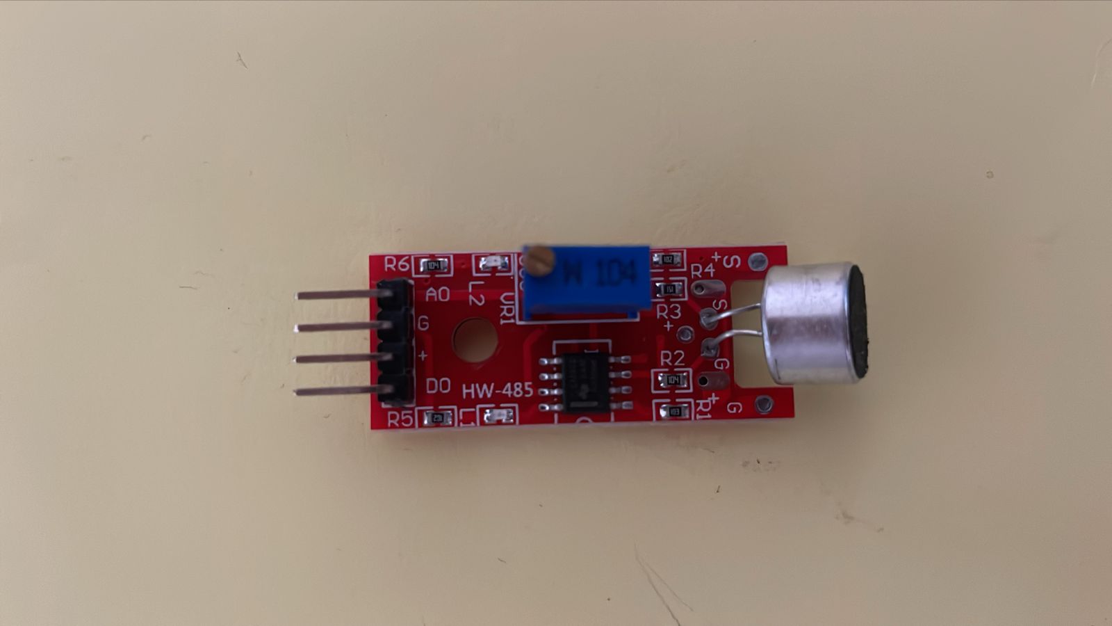
Testing the KY-037 Sound Sensor
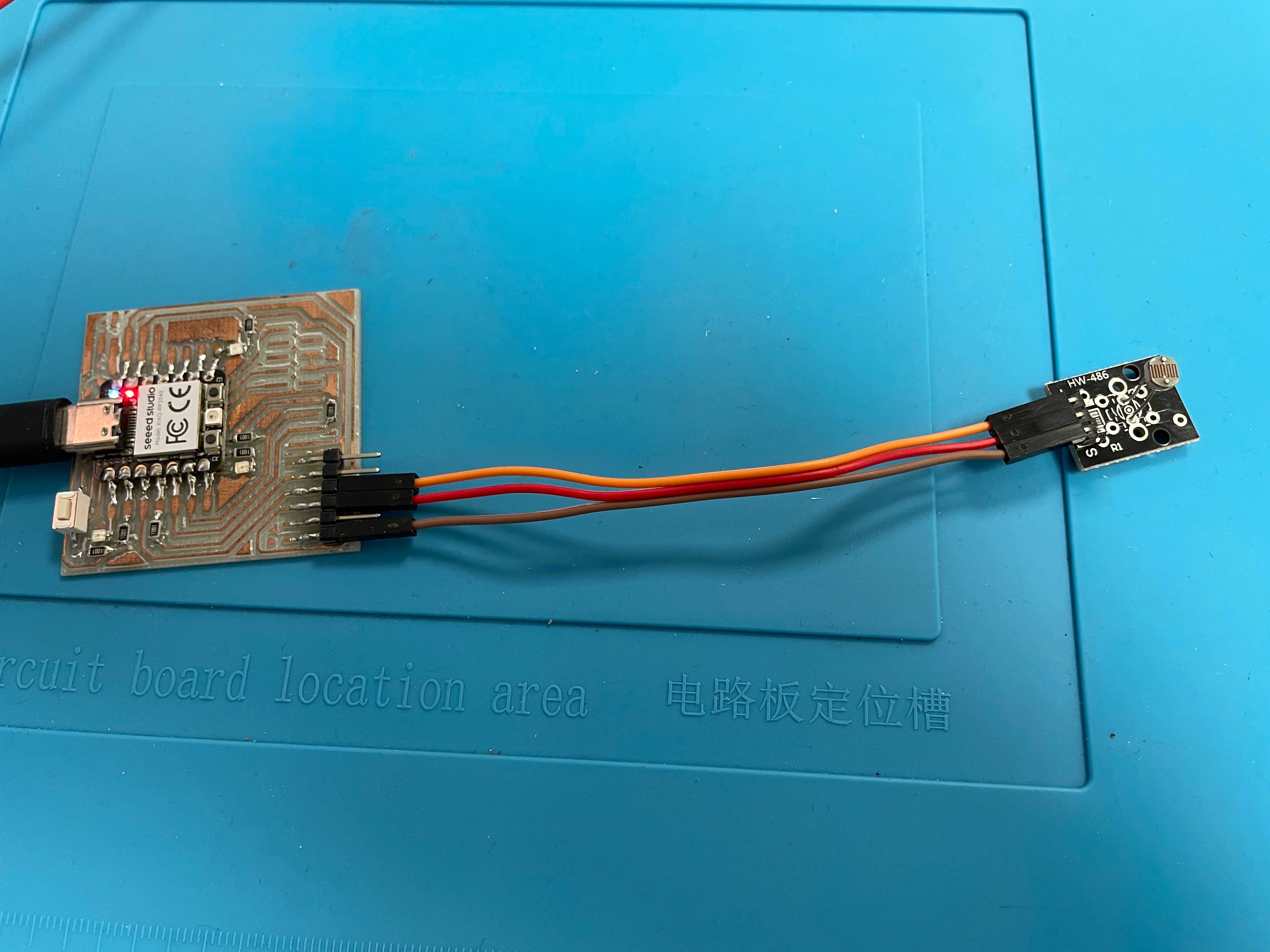
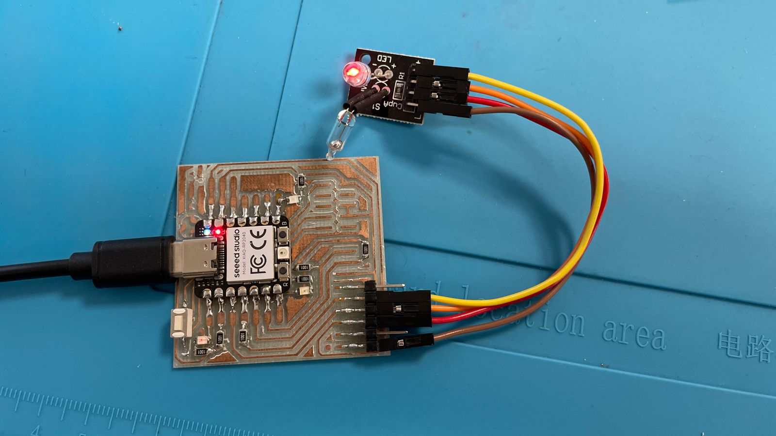
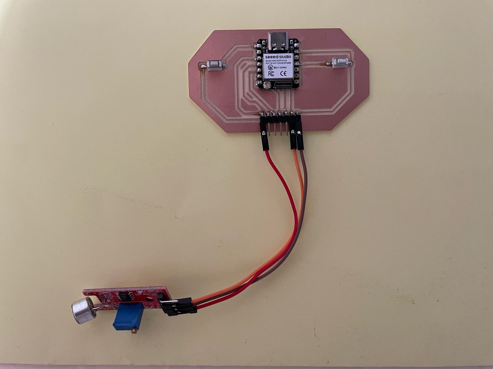
For this part of the assignment, I decided to test a KY-037 sound sensor using my custom crystal holder controller PCB based on the Seeed XIAO ESP32S3. How I made it you ask? check this assignment out: Electronics Production - Week 8 Compared to the other sensors I tested this week — like the photoresistor, mercury tilt sensor, impact sensor, and pushbutton — this one required a bit more patience (and cursing). Between miswiring the analog and digital pins, learning that the sensitivity knob is reversed (thanks, random manufacturer), and discovering that analog output is not as “plug-and-play” as the others... let's just say, the KY-037 demanded some extra emotional bandwidth.
About the KY-037 Sound Sensor
The KY-037 sound sensor is not just a simple microphone. It’s a small sound detection module that includes:
- An electret microphone to capture sound waves (like claps, knocks, or rage screams).
- An onboard op-amp circuit to amplify the signal.
- Two outputs: AO for analog voltage based on volume, and DO for digital threshold detection.
The analog output gives you a continuously varying value based on sound intensity, while the digital output flips HIGH or LOW depending on whether the sound crosses a threshold. That threshold is set by adjusting a small potentiometer — aka, the knob of chaos.
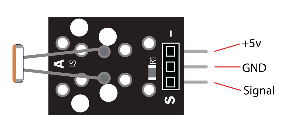
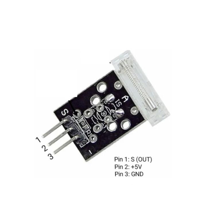
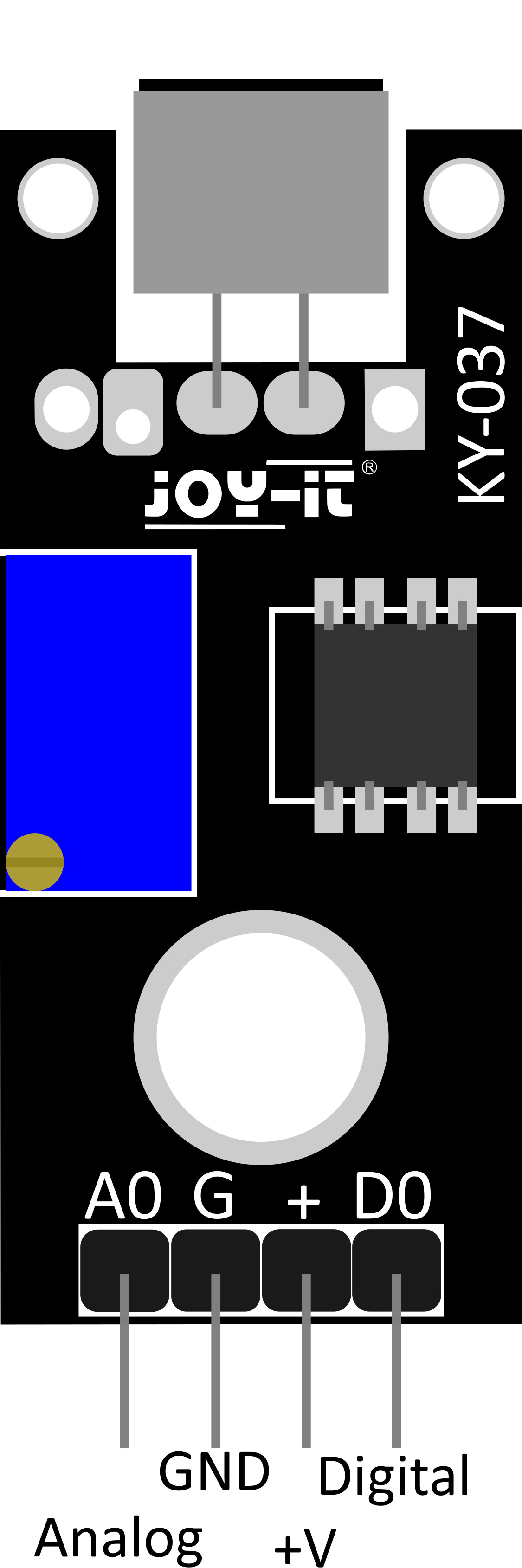
Pinout and Hardware Overview
The module has four pins, typically labeled as follows:
- VCC – Connects to 5V (works with 3.3V too, but not officially recommended)
- GND – Ground
- DO – Digital output (binary HIGH/LOW)
- AO – Analog output (continuous signal)
KY-037 pinout. Yes, it has both AO and DO. Don't mix them up. Ask me how I know.
To adjust the sensitivity of the sensor (for digital output or to fine-tune analog response), the board includes a small trimpot. Depending on the manufacturer, turning it clockwise or counter-clockwise may increase sensitivity. Mine was reversed — of course it was.
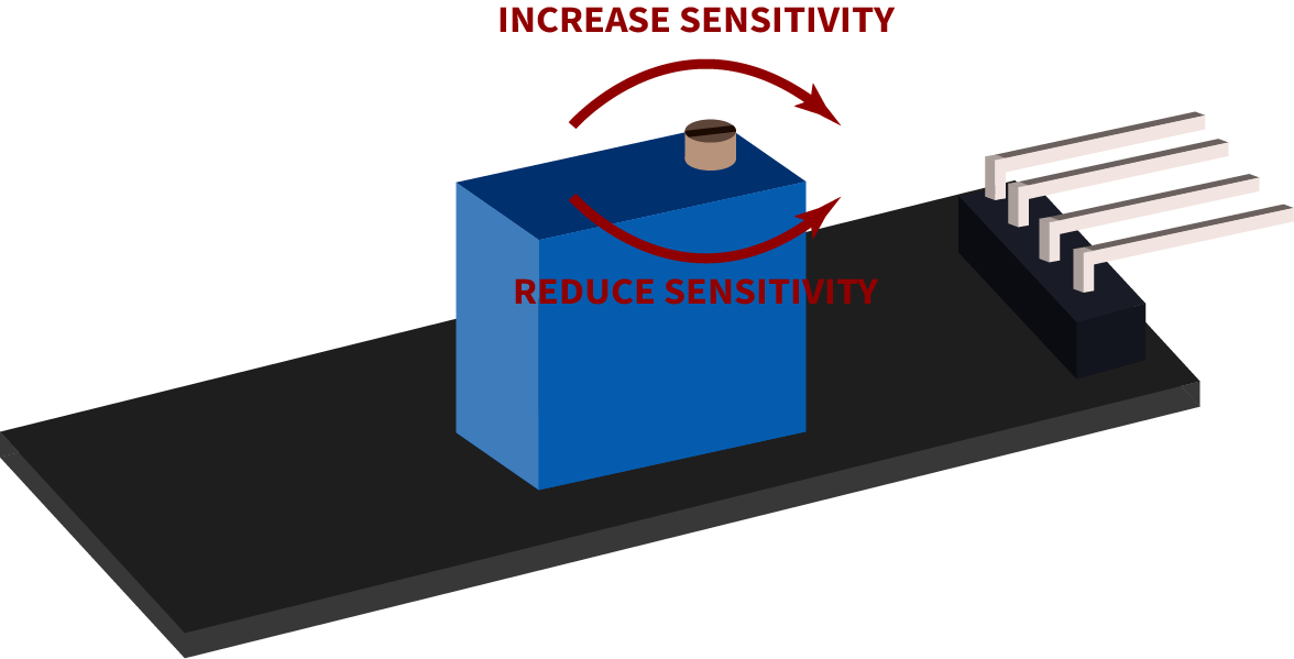
Trimpot knob to adjust sensitivity. Also known as the 'turn until something happens' control.
Step 1: Calibration
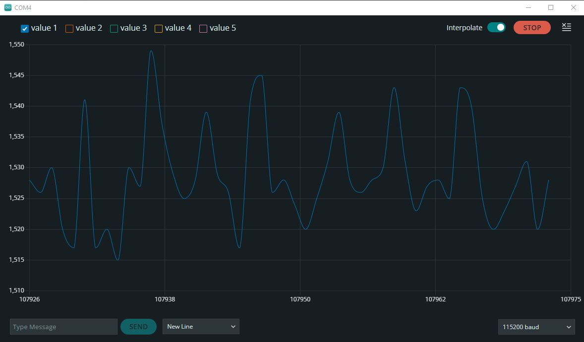
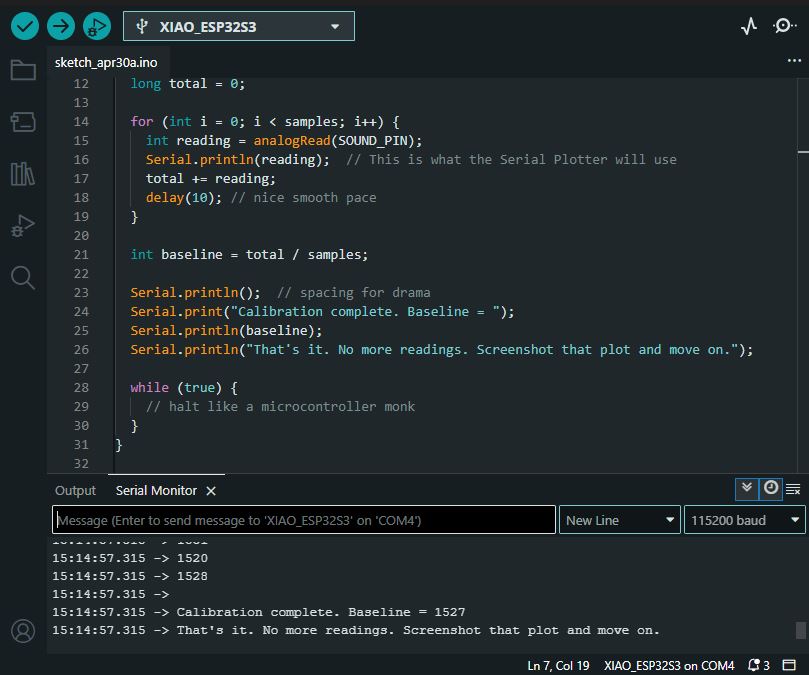
To determine the ambient noise level of my workspace, I wrote a one-shot calibration sketch that samples the analog output of the KY-037 sound sensor exactly 100 times. These values are plotted live using the Serial Plotter. Once sampling is complete, the sketch calculates the average (baseline), prints it in the Serial Monitor, and halts execution. This gives me a clear, one-time snapshot of the environment to define a reliable threshold for later sound detection.
    #define SOUND_PIN A2

    void setup() {
      Serial.begin(115200);
      pinMode(SOUND_PIN, INPUT);

      Serial.println("Taking 100 samples to calculate ambient baseline...");
    }

    void loop() {
      const int samples = 100;
      long total = 0;

      for (int i = 0; i < samples; i++) {
        int reading = analogRead(SOUND_PIN);
        Serial.println(reading);  // Serial Plotter reads this
        total += reading;
        delay(10);
      }

      int baseline = total / samples;

      Serial.println();
      Serial.print("Calibration complete. Baseline = ");
      Serial.println(baseline);
      Serial.println("Done collecting. You can now screenshot the plot.");

      while (true) {
        // Freeze after collecting data
      }
    }
Serial Plotter Output:
Serial Monitor Output:
Step 2: Clap Counter Using Analog Threshold
After several failed attempts to simultaneously get clean waveform data in the Serial Plotter and meaningful messages in the Serial Monitor, I settled on a minimal but effective solution: a clap counter that runs for 10 seconds, plots all analog sound values, and prints a message only when the sound crosses a defined threshold.
This code successfully allowed me to monitor sound levels visually and track discrete sound events (claps) without spamming the Serial Monitor.
#define SOUND_PIN A2
#define THRESHOLD 1580

int clapCount = 0;

void setup() {
  Serial.begin(115200);
  pinMode(SOUND_PIN, INPUT);
}

void loop() {
  const unsigned long duration = 10000;
  unsigned long startTime = millis();

  while (millis() - startTime < duration) {
    int soundLevel = analogRead(SOUND_PIN);

    // Send value to Serial Plotter
    Serial.println(soundLevel);

    // Threshold detection
    if (soundLevel > THRESHOLD) {
      clapCount++;
      Serial.print("[");
      Serial.print(millis());
      Serial.print(" ms] Clap #");
      Serial.print(clapCount);
      Serial.println(" → Calm down, rockstar.");
      delay(300);  // debounce
    }

    delay(50);
  }

  // Test summary
  Serial.print("Test complete. Total claps: ");
  Serial.println(clapCount);

  while (true); // Stop here
}
Test Result
The following video shows the Serial Plotter output and the clap detection working in real time. Each clap crossed the threshold and was registered in the Serial Monitor.
Plot Behavior Observation
An important detail I noticed during the test is that each clap caused a short gap in the waveform on the Serial Plotter. This is not a bug in the code, but a side effect of the delay(300) used for debounce after a threshold is crossed. During this delay, no analog readings are sent to the Plotter, so it appears as a momentary silence or gap.
Additionally, this behavior may be amplified by the low-quality nature of the KY-037 sensor module, which is extremely sensitive, noisy, and lacks proper filtering or consistent signal shaping. If higher fidelity or continuous data is needed, this sensor is likely not suitable.