Esp32camp
Components
| Quantity | Description | Cost (USD) | Photo |
|---|---|---|---|
| 1 | ESP32-CAM | $11.11 | 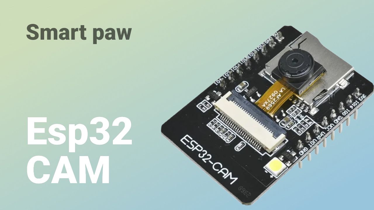 |
| 5 | jumpers | $11.11 | 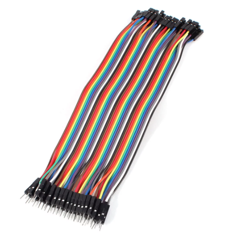 |
| 1 | USBFT232 USB | $10 | 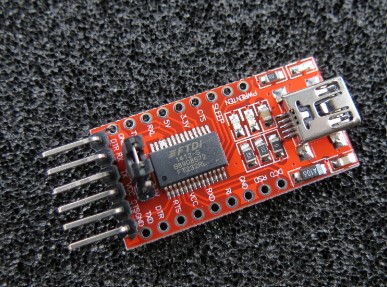 |
Programming ESP32-CAM with FT232 USB without a Programming Board
Connections
Connections between FT232 and ESP32-CAM:
- FT232 VCC to ESP32-CAM 3.3V
- FT232 GND to ESP32-CAM GND
- FT232 TX to ESP32-CAM U0R
- FT232 RX to ESP32-CAM U0T
- FT232 RTS to ESP32-CAM IO0 (for programming mode)
- FT232 DTR to ESP32-CAM RST
Additional Connection for Programming Mode:
To put the ESP32-CAM in programming mode, connect the IO0 pin to GND during the reset. You can do this temporarily with a jumper:
- ESP32-CAM IO0 to ESP32-CAM GND (temporarily during reset)
Software
Make sure you have the Arduino IDE installed and the ESP32 library added to it.
Installing ESP32 Library in Arduino IDE:
- Open Arduino IDE.
- Go to File > Preferences.
- In the Additional Board Manager URLs field, add the following URL:
- Go to Tools > Board > Board Manager.
- Search for ESP32 and install the library.
https://dl.espressif.com/dl/package_esp32_index.json
Arduino IDE Configuration:
- Select Tools > Board > ESP32 Arduino > AI Thinker ESP32-CAM.
- Configure the following options in the Tools menu:
- Flash Mode: QIO
- Flash Frequency: 40MHz
- Upload Speed: 115200
- Port: Select the COM port corresponding to the FT232 USB
Example Code:
#include "esp_camera.h"
#include

// Replace with your network credentials
const char* ssid = "your_SSID";
const char* password = "your_PASSWORD";

void startCameraServer();

void setup() {
  Serial.begin(115200);
  WiFi.begin(ssid, password);

  while (WiFi.status() != WL_CONNECTED) {
    delay(500);
    Serial.print(".");
  }
  Serial.println("");
  Serial.println("WiFi connected");

  startCameraServer();
}

void loop() {
  delay(10000);
}
Programming
- Connect ESP32-CAM IO0 to GND (temporarily for programming mode).
- Connect the FT232 to the USB port of your computer.
- Upload the code from the Arduino IDE.
- Once the upload is complete, disconnect the jumper between ESP32-CAM IO0 and GND.
- Reset the ESP32-CAM (by disconnecting and reconnecting the power or using a reset button if available).
Completion
Once you have uploaded the code, your ESP32-CAM should be ready and connected to your Wi-Fi network, accessible according to the functions provided in your code.
Programming
Arduino ESP CAM
This Arduino code uses an ESP32 to connect to a WiFi network, initialize a camera, and send data to a web server.
				// Included Libraries
				#include "esp_camera.h"             // Library to handle the ESP32 camera
				#include <WiFi.h>                   // Library to connect to WiFi networks
				#include <HTTPClient.h>             // Library to make HTTP requests
				#include <WiFiClientSecure.h>       // Library to handle secure WiFi connections

				// WiFi Network and Server Configuration
				const char* ssid = "frank";                 // WiFi network SSID
				const char* password = "franlopez";         // WiFi network password

				const char* serverName = "https://7b1bd7318-bc4d-4740-a62d-d7195741dcee-00-2biv5sob6tgpp.spock.replit.dev/upload2.php"; // HTTPS server URL

				// Camera Model Definition
				#define CAMERA_MODEL_AI_THINKER
				#include "camera_pins.h"   // Includes the configuration of the camera pins

				void setup() {
				Serial.begin(115200);  // Start serial communication at 115200 baud

				camera_config_t config;
				config.ledc_channel = LEDC_CHANNEL_0;
				config.ledc_timer = LEDC_TIMER_0;
				config.pin_d0 = Y2_GPIO_NUM;
				config.pin_d1 = Y3_GPIO_NUM;
				config.pin_d2 = Y4_GPIO_NUM;
				config.pin_d3 = Y5_GPIO_NUM;
				config.pin_d4 = Y6_GPIO_NUM;
				config.pin_d5 = Y7_GPIO_NUM;
				config.pin_d6 = Y8_GPIO_NUM;
				config.pin_d7 = Y9_GPIO_NUM;
				config.pin_xclk = XCLK_GPIO_NUM;
				config.pin_pclk = PCLK_GPIO_NUM;
				config.pin_vsync = VSYNC_GPIO_NUM;
				config.pin_href = HREF_GPIO_NUM;
				config.pin_sccb_sda = SIOD_GPIO_NUM;
				config.pin_sccb_scl = SIOC_GPIO_NUM;
				config.pin

	_pwdn = PWDN_GPIO_NUM;
				config.pin_reset = RESET_GPIO_NUM;
				config.xclk_freq_hz = 20000000;
				config.pixel_format = PIXFORMAT_JPEG;

				// Start the camera with the defined configuration
				esp_err_t err = esp_camera_init(&config);
				if (err != ESP_OK) {
				Serial.printf("Camera error: %s\n", esp_err_to_name(err));
				return;
								}

				// Start WiFi
				WiFi.begin(ssid, password);
				while (WiFi.status() != WL_CONNECTED) {
				delay(500);
				Serial.print(".");
								}
				Serial.println("Connected to WiFi");
							}
Detailed Explanation
Included Libraries: The code includes several essential libraries to handle the ESP32 camera, connect to WiFi networks, and make HTTP requests.
WiFi Network and Server Configuration: The WiFi network credentials and the server URL to which the data will be sent are defined.
Camera Model Definition: The model of the camera used is defined, and the file containing the configuration of the specific pins for that model is included.
Setup Function: Initializes serial communication, configures the camera pins, initializes the camera, and connects the ESP32 to the WiFi network.
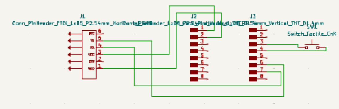
additional information
Additionally, I gave myself the task of making this schematic for a PCB to make the programming mode easier. However, I did not manufacture it due to time and economic issues.