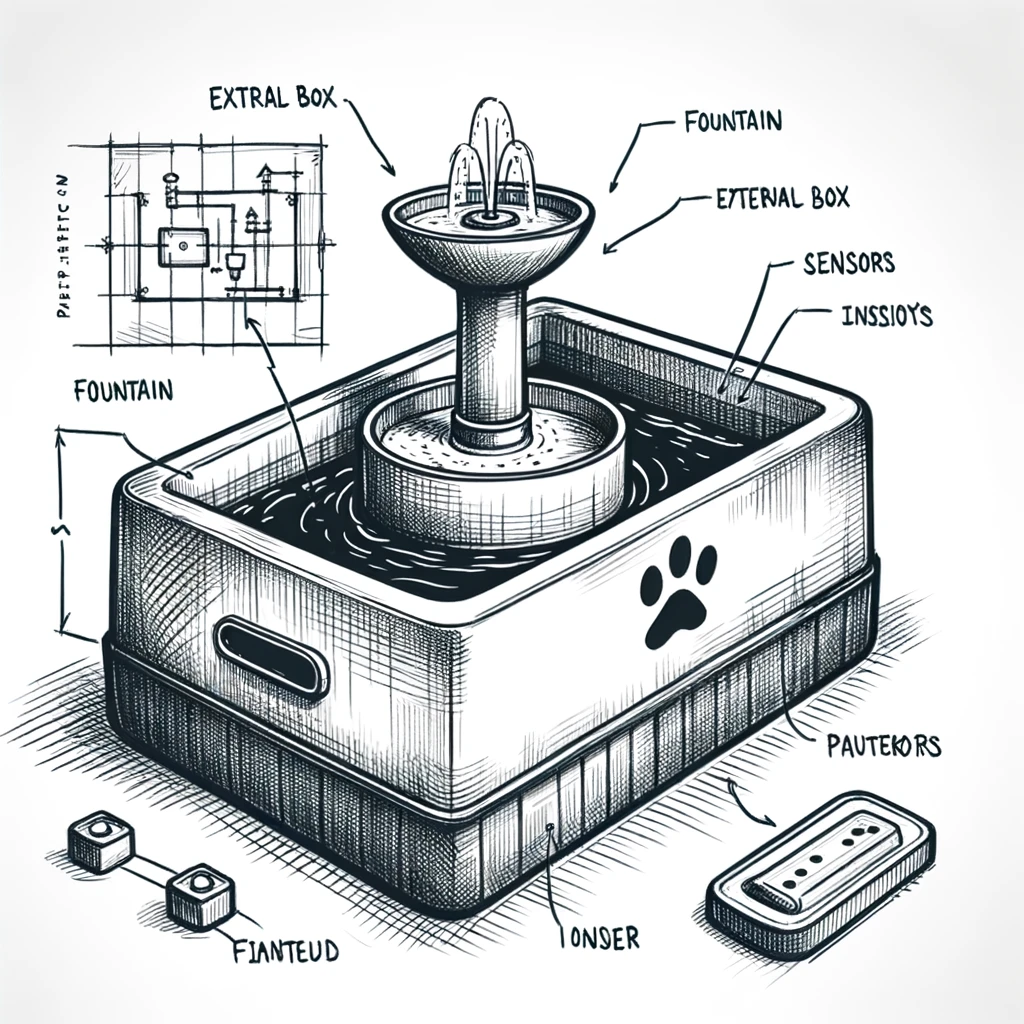
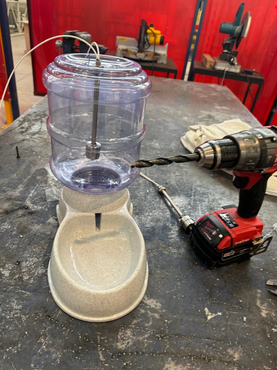
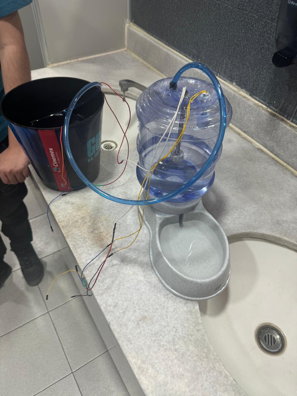
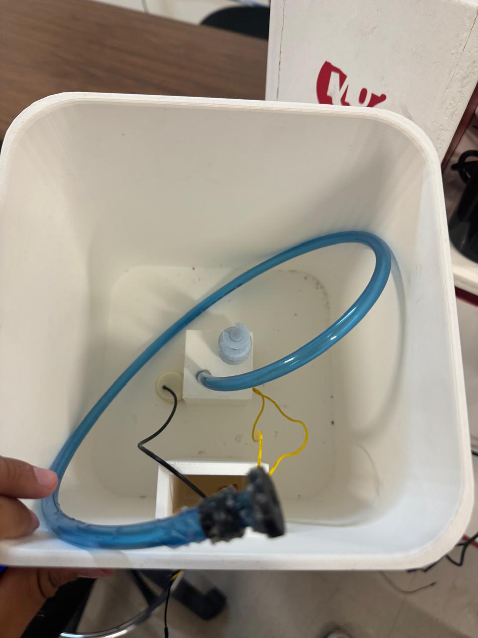
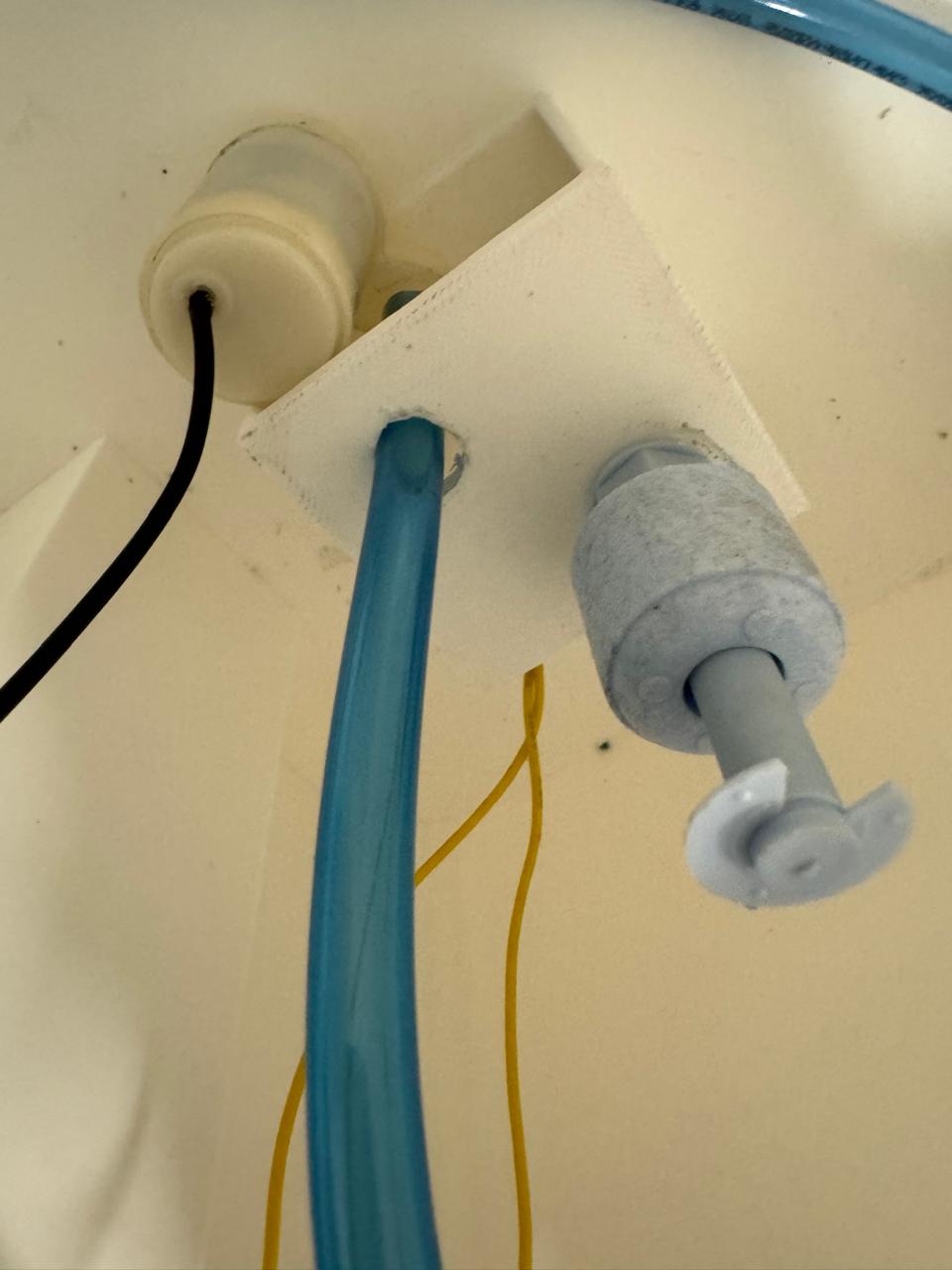
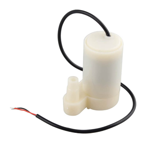
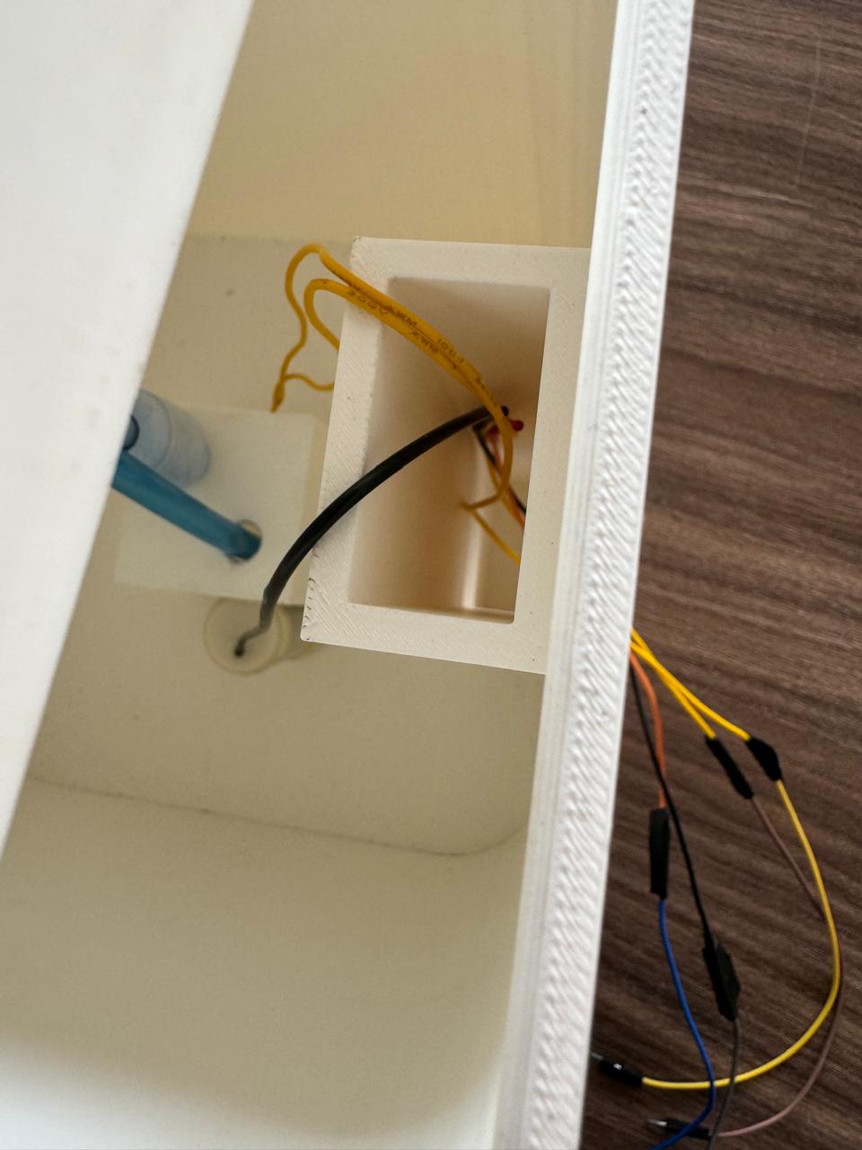
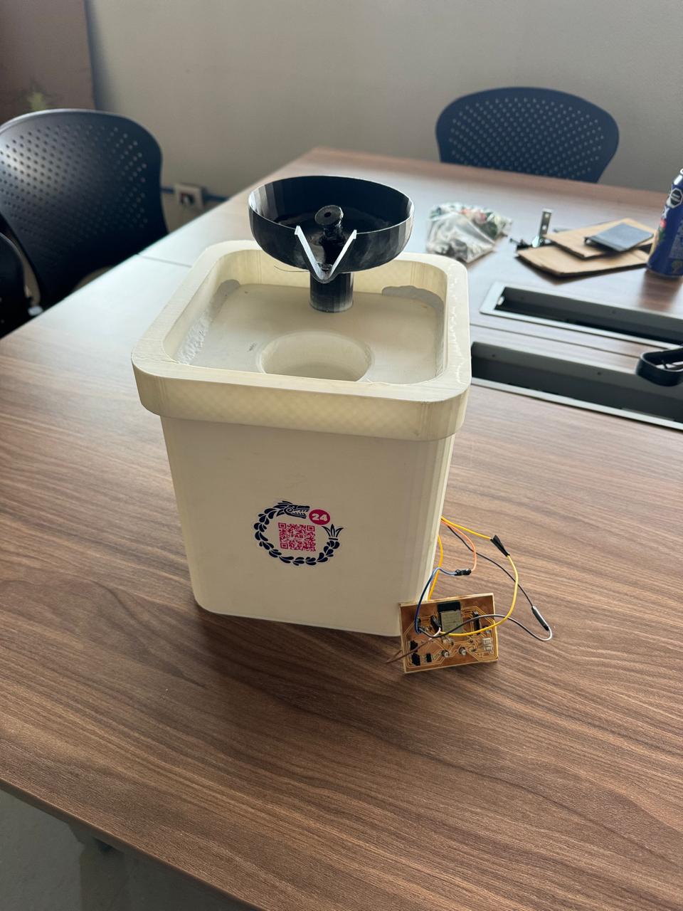
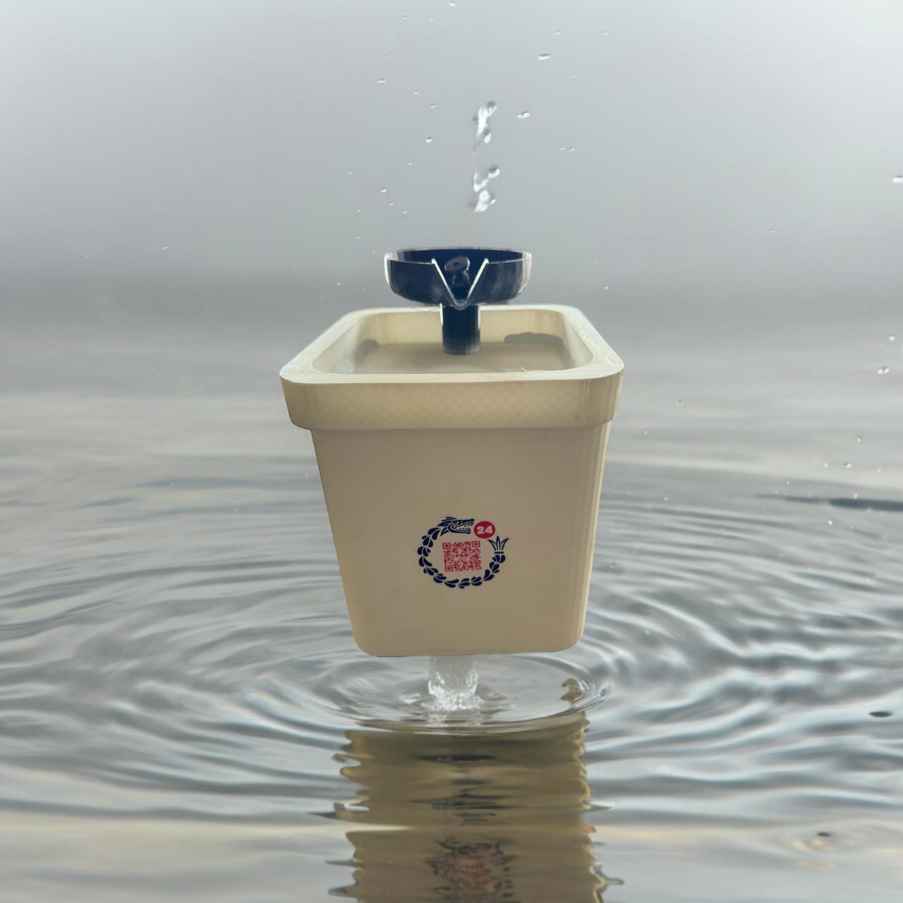
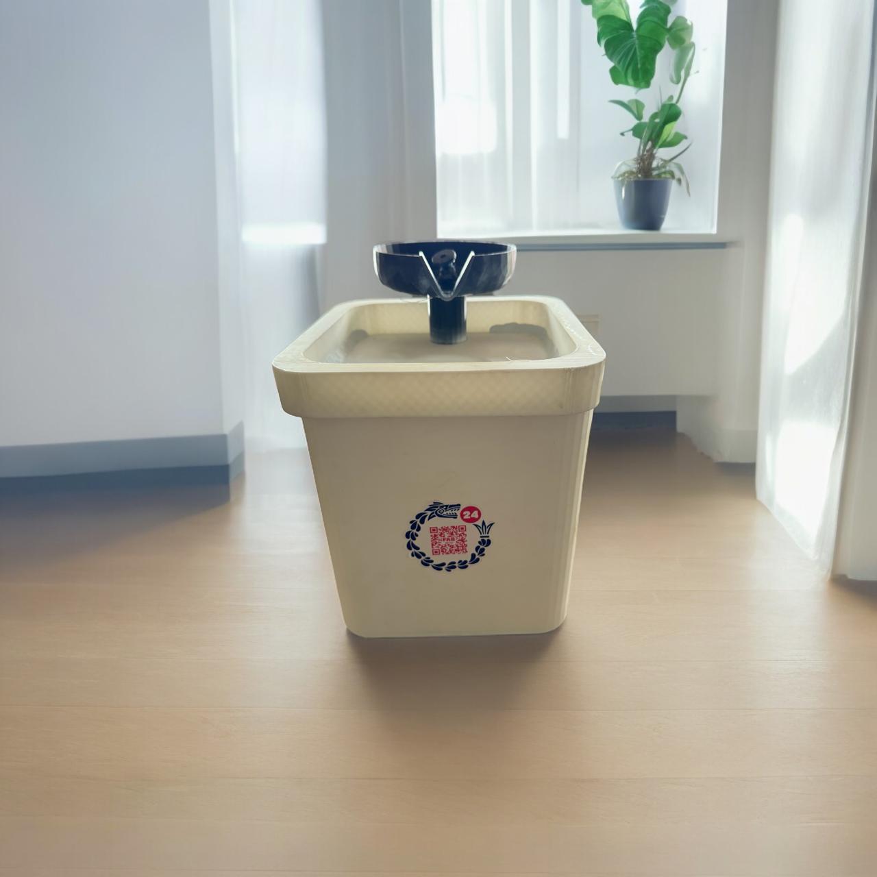
The initial idea was 2 sensors and 1 pump that could supply water from an external place every time it was finished, but when it came to drilling the jug to insert the motors and the hose, there was an air leak which the system could not do. compression causing the water to always be irrigated, so I had to redesign the drinking fountain, making it like a fountain and only using a sensor which detects when there is no water and turns off the pump, the disadvantage is that here the water is provided the user
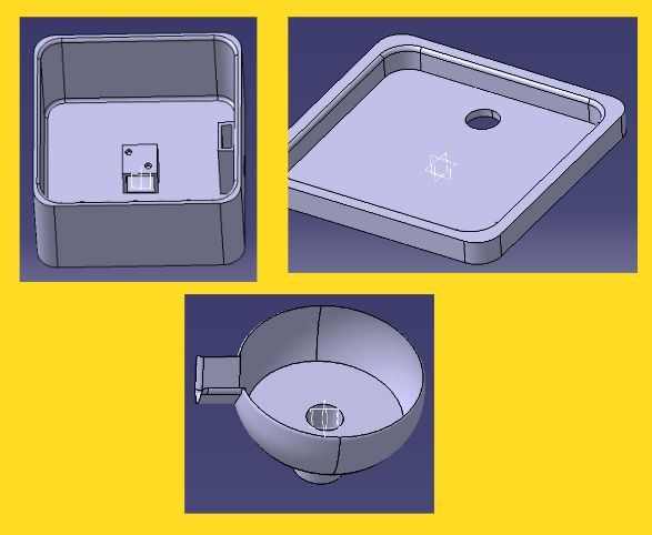
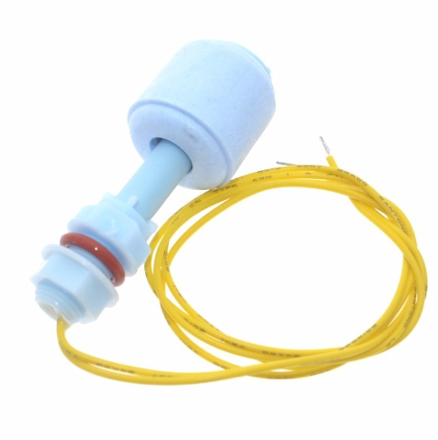
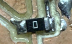
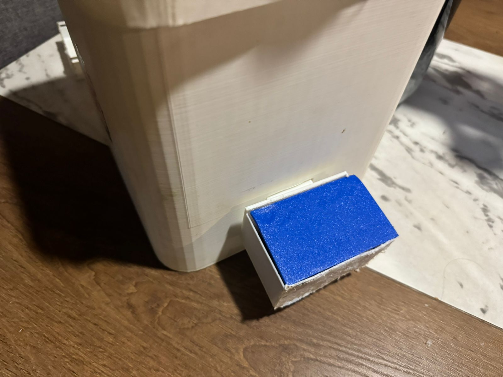
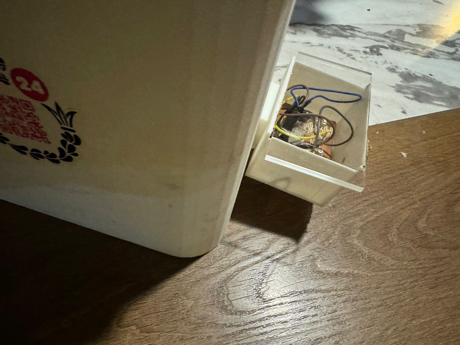
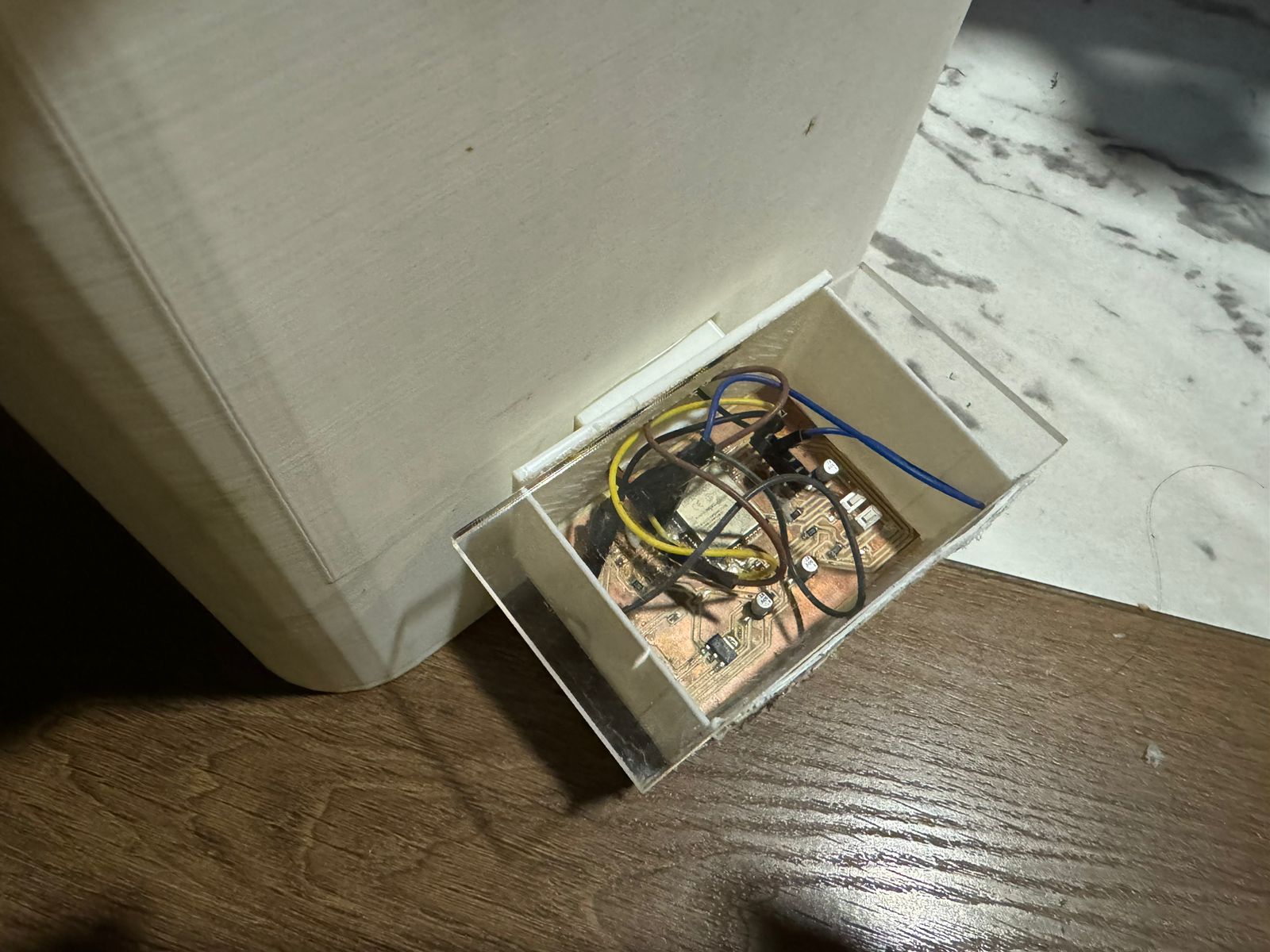
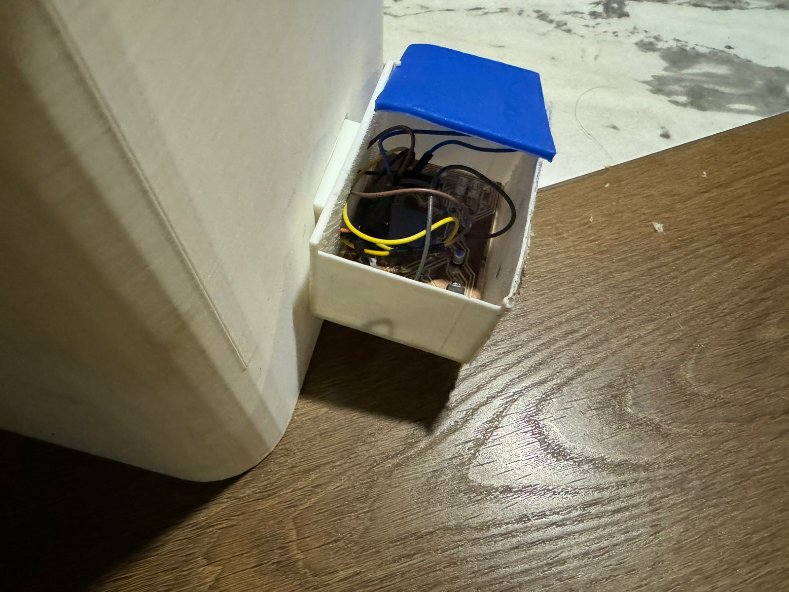
In these images, we can observe that the water dispenser has space for a pump with a hose responsible for cycling the water until it runs out. The blue component next to it is a level sensor, which ensures that when the water is depleted, it signals the pump to stop supplying water, thereby protecting the pump from damage and preventing unnecessary energy consumption. When the user refills the water, the sensor detects the new water level, reactivates the pump, and resumes its operation.
| Description |
Cost (USD) |
Photo |
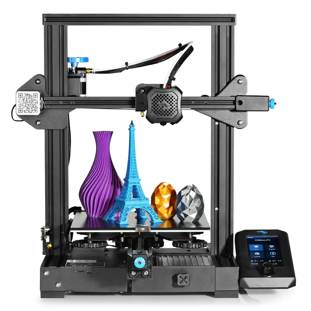
| 3D Printing (Approx. 1 kg) |
$35 |
 |
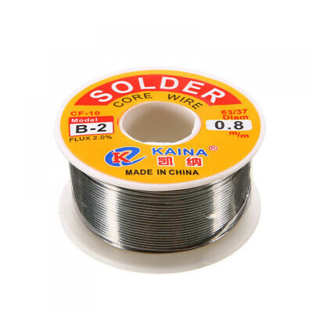
| Soldering |
$5.56 |
 |
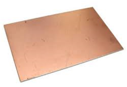
| Copper for PCB |
$5.56 |
 |
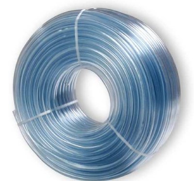
| 50 cm water hose |
$2.5 |
 |
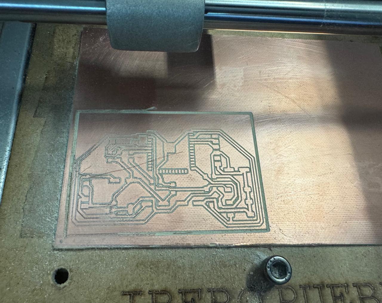
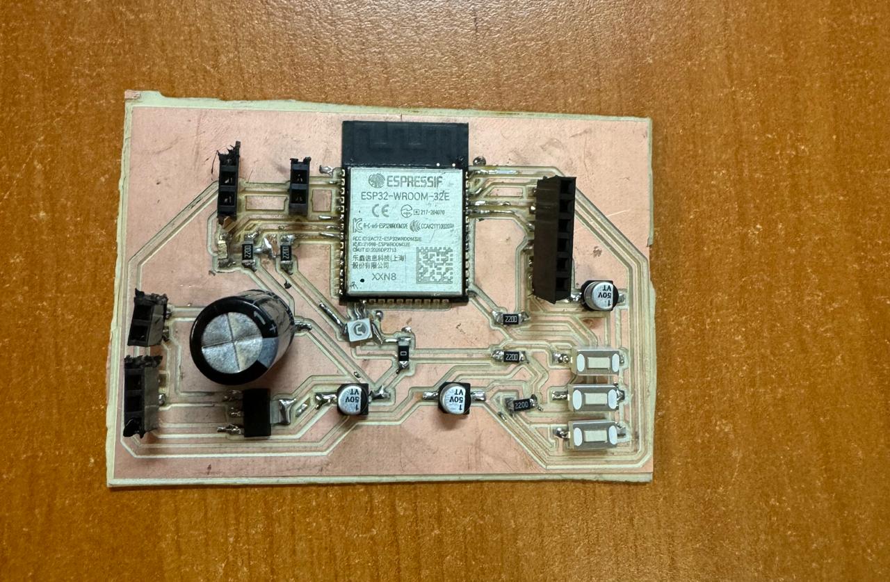
electronic production
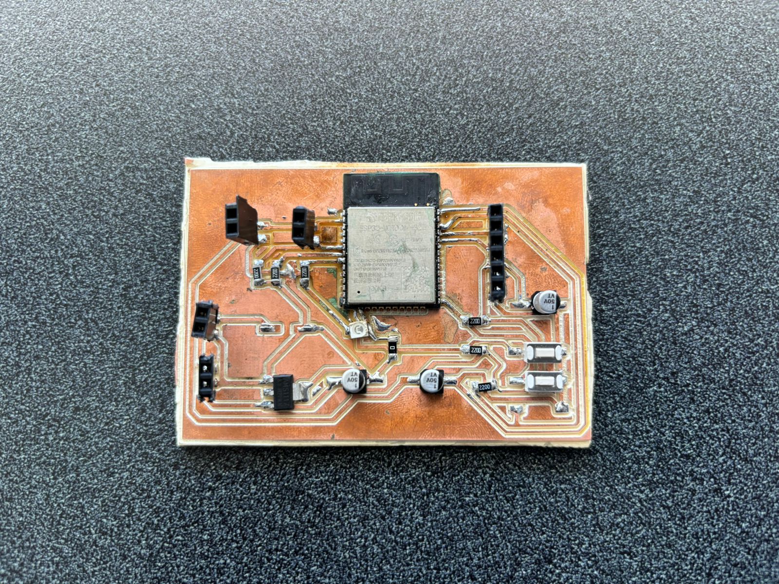
PCB
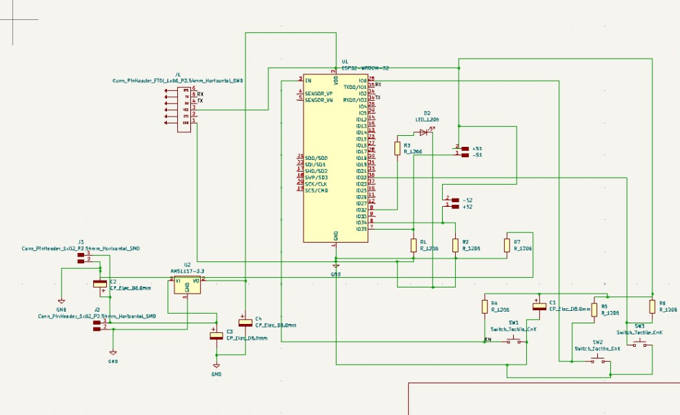
ESP32 Controlled Water Dispenser Schematic Explanation
This schematic is a PCB design for a water dispenser system controlled by an ESP32. Below is an explanation of each part of the schematic:
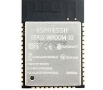
1. Microcontroller ESP32 (U1)
- The brain of the system that will control the water dispenser. It has multiple GPIO (General Purpose Input/Output) pins used to connect sensors and the water pump.
- Highlighted pins:
- EN: Enable pin for the ESP32.
- GPIO: General purpose input/output pins used to connect sensors, the pump, and other components.
2. Power Supply
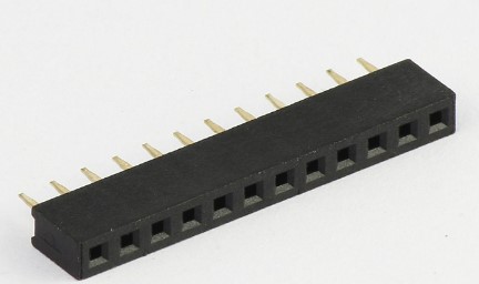
- J1 and J3: Pin header connectors that allow the connection of sensors and other external devices.
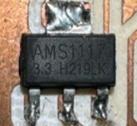
- U2 (AMS1117-3.3): Voltage regulator that converts the input voltage to 3.3V needed to power the ESP32.
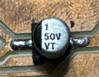
- C2, C3, C4: Decoupling capacitors to stabilize the voltage and filter noise.
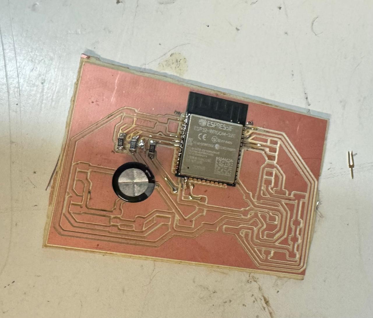
3. Relay (RL1)
- Used to control the water pump, allowing the ESP32 to turn the pump on or off as needed.
- D2: LED diode indicating the relay status.
- Q1: Transistor acting as a switch to control the relay.
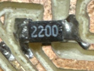
- R1, R2, R3: Resistors that limit the current through the LED and transistor.
4. Sensors
- Connections for two sensors (likely water level or flow sensors) connected through pin headers (J2 and J3).
- R4, R5, R6, R7: Pull-up/pull-down resistors to ensure the sensors provide stable signals to the ESP32.
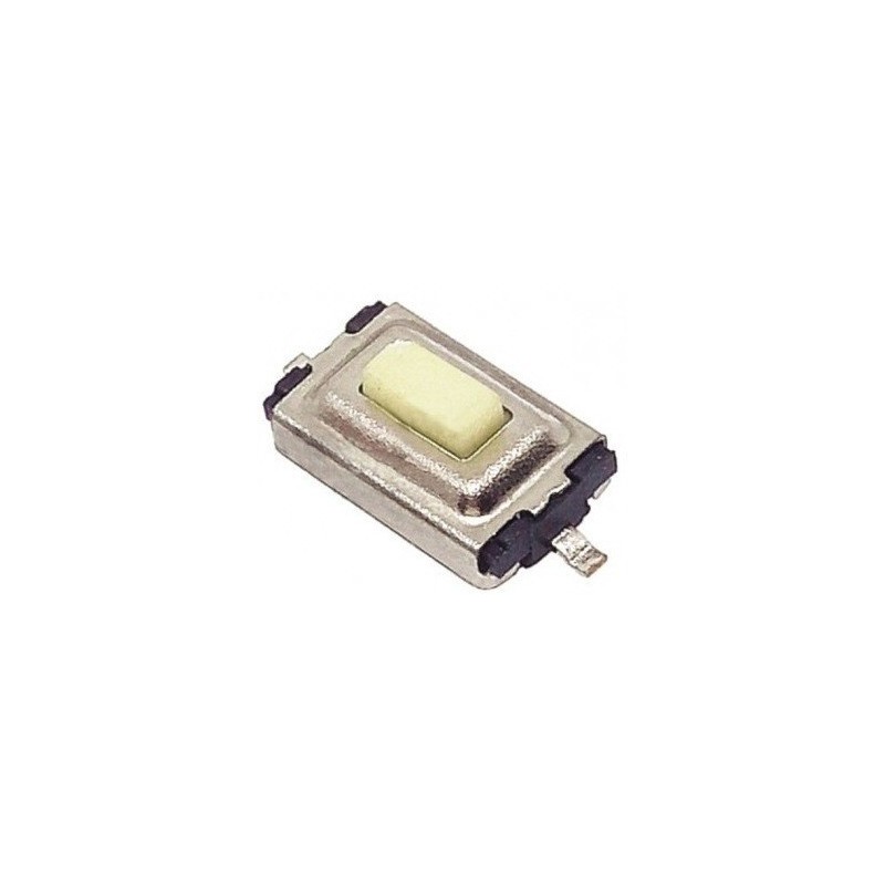
5. Tactile Switches (SW1, SW2, SW3)
- These switches allow manual interaction with the system, such as manually turning the pump on/off or adjusting settings.
- R8, R9, R10: Resistors that limit the current through the switches and ensure stable signals.
6. Capacitors
- C1, C2, C3, C4: Help filter and stabilize signals and voltage in different parts of the circuit.
7. Connections
- VCC and GND: Voltage and ground connections distributed throughout the circuit to power components and establish a common reference point.
This schematic shows a typical design of a control system based on the ESP32 with the ability to control a water pump via a relay and receive inputs from multiple sensors, along with a simple user interface with tactile switches.
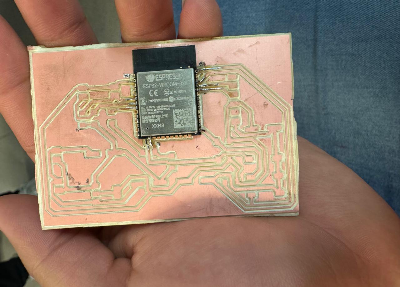
ESP32 Design Improvements
The black top part of the ESP32 is an antenna. Currently, my design operates without interference, but it is important to consider some improvements to ensure optimal efficiency in the long term:
PCB Design
It is crucial to ensure that there is no copper directly under the antenna when milling the PCB. This helps to prevent signal interference and allows the antenna to operate effectively. In my current design, I have considered this aspect to avoid potential issues.
Placement
Similar to development boards, it is recommended to place the antenna outside the main area of the PCB or on the edge of the board. This minimizes obstructions and maximizes signal strength. Although my current design is functioning well, considering this recommendation can further improve performance.
Clearance
Maintaining sufficient clearance around the antenna is essential to avoid interference from other components and traces. I have tried to follow this practice in my design, but it is always good to review and ensure it is adequately met.
Integrating these points into the design can significantly improve the performance of the ESP32 antenna on my PCB. Although I currently have no interference issues, considering these improvements can be beneficial for future developments.
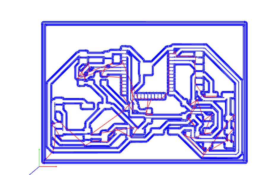
Download to cut PCB
Programming of Sensors and Actuators:
This PHP file manages reading and writing the water dispenser level in a text file and displays it in real-time.
<?php
// If the datosbebedero.txt file doesn't exist, create it with the initial value "0\r\n".
if (!file_exists("datosbebedero.txt")) {
    file_put_contents("datosbebedero.txt", "0\r\n");
}

// If a value is sent via a POST form, save it in the datosbebedero.txt file.
if (isset($_POST['valor'])) {
    $VAR1 = $_POST['valor']; // Assign the POST value to the $VAR1 variable
    $TEXTO = $VAR1 . "\r\n"; // Add a new line to the value
    file_put_contents("datosbebedero.txt", $TEXTO); // Save the value in the file
}

// Read the content of the datosbebedero.txt file.
$ARCHIVO = file_get_contents("datosbebedero.txt");
// Find the position of the first newline character.
$pos = strpos($ARCHIVO, "\r\n");
// Extract the value up to the first newline character.
$VAR1 = substr($ARCHIVO, 0, $pos);
?>

<!DOCTYPE html>
<html>
<head>
    <!-- Refresh the page every 1 second -->
    <meta http-equiv="refresh" content="1">
</head>
<body>
    <!-- Display the value stored in $VAR1 on the page -->
    <p style="font-size:20px; font-family:'Segoe UI', Tahoma, Geneva, Verdana, sans-serif; color: #707070; line-height: 0;"><?php echo $VAR1 ?> </p>
</body>
</html>
Code Explanation
- File Creation: Checks if the `datosbebedero.txt` file exists. If not, it creates it with "0\r\n" as the initial value.
- Value Update: If a value is sent via a POST form, it saves this value in `datosbebedero.txt`.
- Value Reading: Reads the content of the file and extracts the value up to the first newline character.
- Auto Refresh: Reloads the page every second to show the updated value.
Download code
Arduino Code for Water Dispenser Control
This Arduino code reads the water level sensor and controls a pump based on the sensor state. It also sends the sensor and pump states to a server.
// Libraries included
#include <WiFi.h>
#include <HTTPClient.h>

// Global Variables
String serverName = "https://7b1bd7318-bc4d-4740-a62d-d7195741dcee-00-2biv5sob6tgpp.spock.replit.dev/bebedero.php";
int sensorLevel = 34; // Pin where the level sensor is connected
int pumpPin = 5; // Pin where the pump is connected

void setup() {
    Serial.begin(115200);
    pinMode(sensorLevel, INPUT);
    pinMode(pumpPin, OUTPUT);

    WiFi.begin("frank", "franlopez");
    while (WiFi.status() != WL_CONNECTED) {
        delay(500);
        Serial.print(".");
    }
    Serial.println("WiFi connected.");
}

void loop() {
    if (WiFi.status() == WL_CONNECTED) {
        HTTPClient http;
        http.begin(serverName);
        http.addHeader("Content-Type", "application/x-www-form-urlencoded");

        int sensorState = digitalRead(sensorLevel);
        int pumpState = (sensorState == HIGH) ? HIGH : LOW;
        digitalWrite(pumpPin, pumpState);

        String httpRequestData = "sensor=" + String(sensorState) + "&pump=" + String(pumpState);
        int httpResponseCode = http.POST(httpRequestData);

        if (httpResponseCode > 0) {
            String response = http.getString();
            Serial.println(httpResponseCode);
            Serial.println(response);
        } else {
            Serial.print("Error on sending POST: ");
            Serial.println(httpResponseCode);
        }

        http.end();
    }

    delay(1000);
}
The water dispenser on the page is shown as 1 or 0 due to the water level sensor. If the sensor detects no water, it will switch to 0, turning off the pump and indicating that 0 means no water, prompting the user to add more water. If it is at 1, there is water, and the pump will be running.
Download code
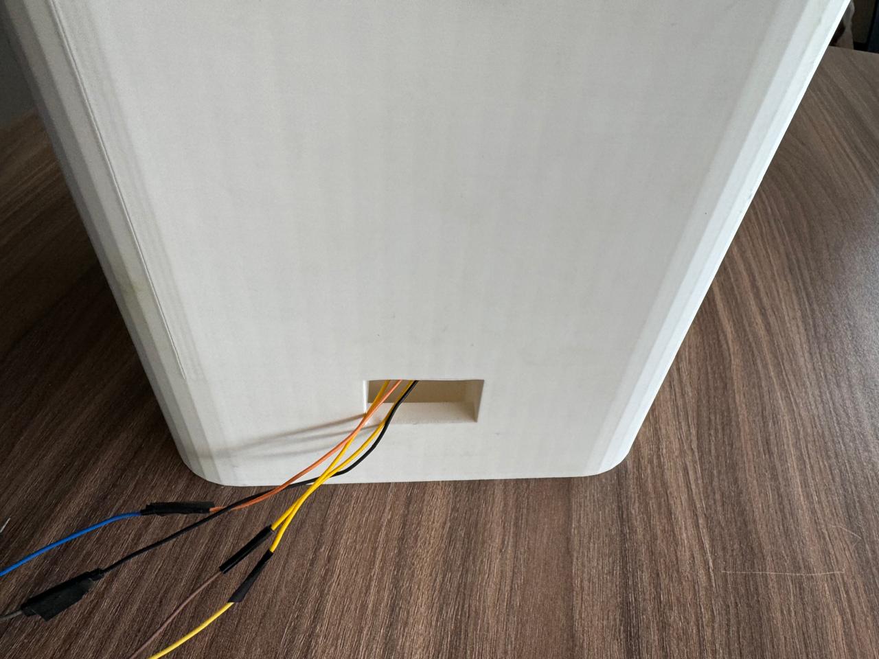
system integration
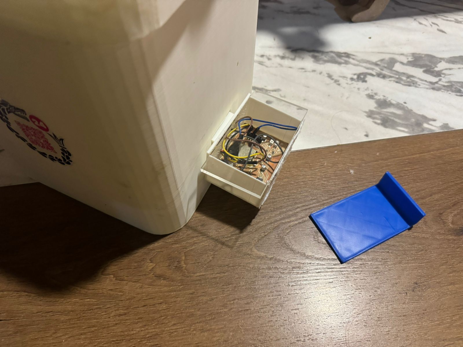
To store the electronic components, I created a 3D printed box that can be closed with either an acrylic cover for visibility of the components or a 3D printed cover that does not allow visual access.
Download box
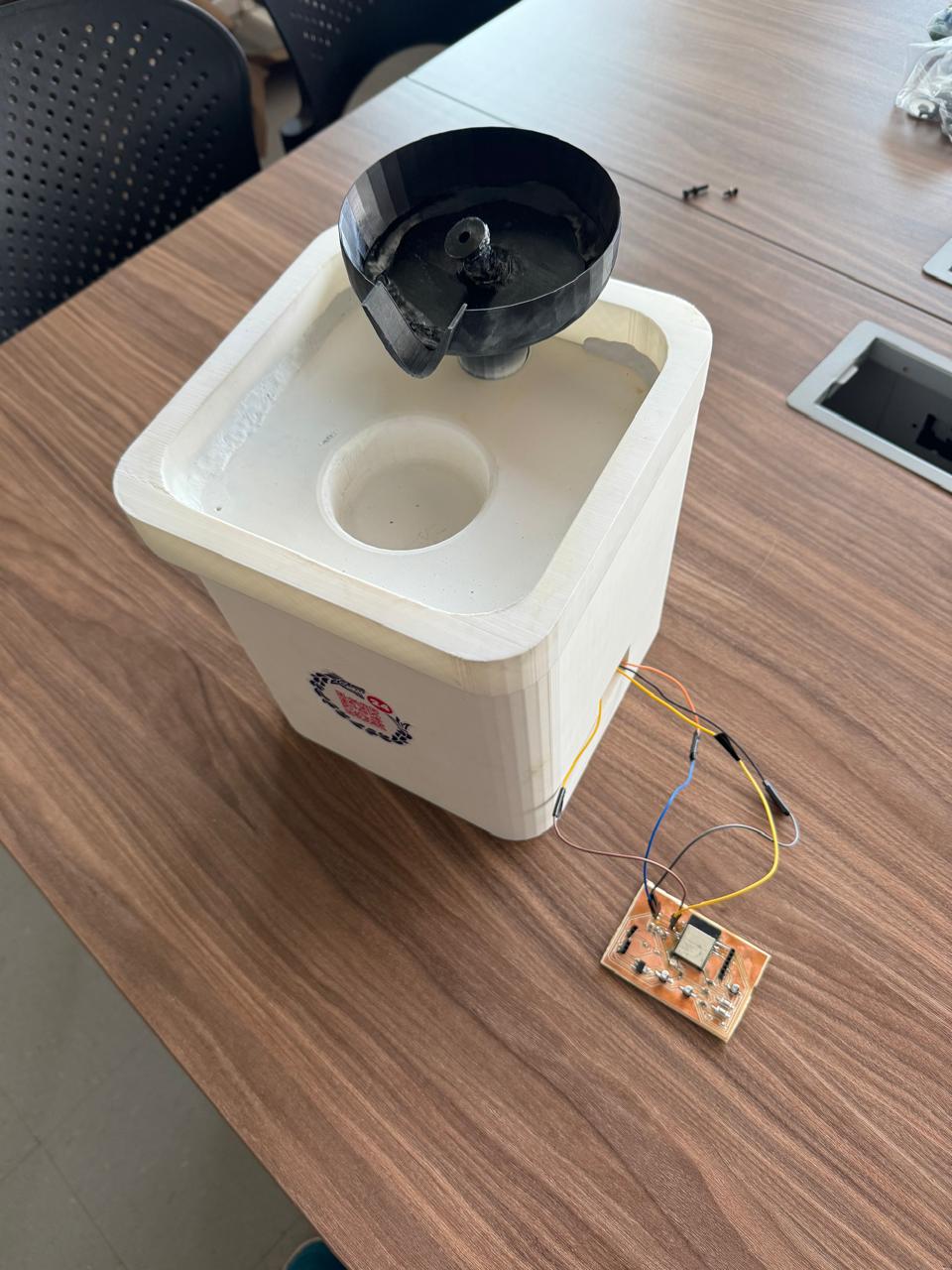
Final water dispenser prototype.
files