Wildcard week
Introduction
In the field of industrial robotics, tools and programming fundamentals are essential for the efficient development and operation of robots like those from KUKA. These tools and fundamentals provide engineers and programmers with the necessary capabilities to design, control, and optimize the functioning of robots in a variety of industrial applications.
This practice focuses on exploring the specific tools, fundamentals, and basic programming movements for KUKA robots. These robots, known for their precision, versatility, and reliability, are widely used in various industries, from automotive to electronic product manufacturing. Understanding in detail how they work and how to program them is essential to maximize their potential and efficiency in the industrial environment.
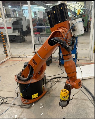
KUKA
| Characteristic | Description |
|---|---|
| Model | KUKA KR 360 FORTEC |
| Type | Industrial robot |
| Maximum load capacity | 360 kg |
| Maximum reach | 2826 mm |
| Number of axes | 6 |
| Repeatability | ±0.08 mm |
| Robot weight | Approx. 2370 kg |
| Range of motion (axis 1) | ±185° |
| Range of motion (axis 2) | +35° to -130° |
| Range of motion (axis 3) | +154° to -119° |
| Range of motion (axis 4) | ±350° |
| Range of motion (axis 5) | ±122.5° |
| Range of motion (axis 6) | ±350° |
| Maximum speed (axis 1) | 82°/s |
| Maximum speed (axis 2) | 82°/s |
| Maximum speed (axis 3) | 82°/s |
| Maximum speed (axis 4) | 109°/s |
| Maximum speed (axis 5) | 109°/s |
| Maximum speed (axis 6) | 180°/s |
| Protection | IP 65 |
| Mounting | Floor |
| Compatible controller | KUKA KR C4 |
| Typical applications | Material handling, machine loading/unloading, welding, assembly, palletizing |
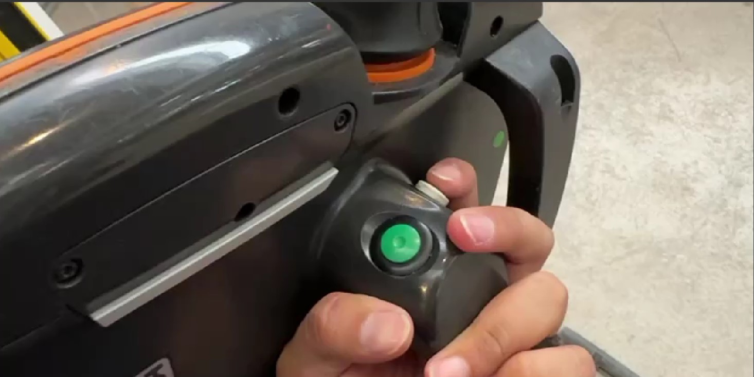
Deadman Switch in KUKA
The deadman switch is a safety feature on the KUKA smartPAD that ensures the operator maintains active control of the robot. It works with three positions:
- Rest Position: Not pressed, the robot is stopped.
- Intermediate Position: Light pressure, the robot is ready to operate.
- Safety Position: Full pressure, the robot stops as an emergency measure.
How to Press the Deadman Switch on KUKA:
- Grab the KUKA smartPAD with one hand.
- Press the switch lightly until you feel a slight resistance.
- Keep that light pressure to allow the robot to move.
- Don't press too hard or the robot will stop.
Types of Movements in KUKA Robots
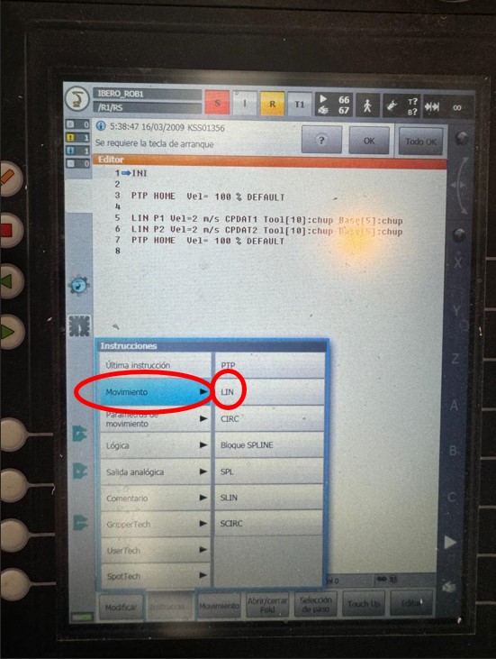
- Linear Movements (LIN):
- Description: Straight line movement from one point to another.
- Applications: Tasks requiring precise paths, such as welding or cutting.
- Example: Straight movement from point A to point B.
- Point-to-Point Movements (PTP):
- Description: Fast movement between two points, regardless of the path.
- Applications: Fast movements without precise path requirements.
- Example: Quick movement from point A to point B.
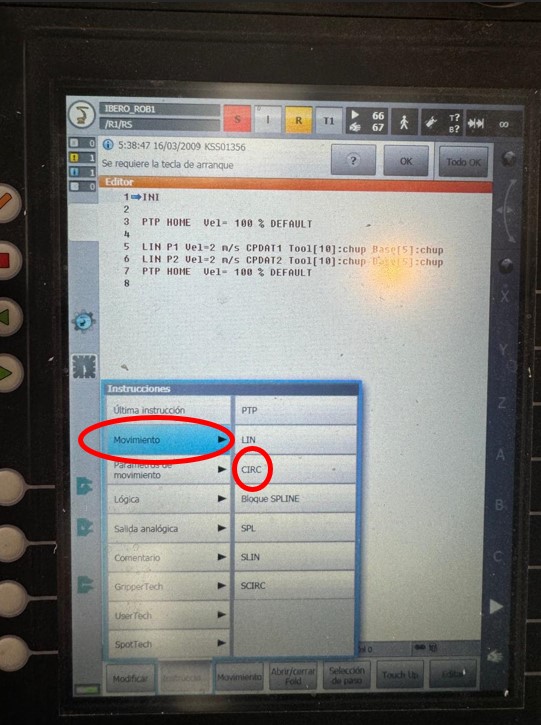
- Circular Movements (CIRC):
- Description: Movement along a circular arc defined by an intermediate point and an endpoint.
- Applications: Tasks requiring curved paths, such as object manipulation.
- Example: Movement from point A to point C passing through point B, forming an arc.
- SPLINE Movements:
- Description: Movement along a path defined by several control points, allowing smooth and complex trajectories.
- Applications: Smooth and continuous movements, such as in polishing or applying adhesives.
- Example: Smooth trajectory passing through multiple control points.
In my practice with the KUKA 6-axis robot, I have learned to move the robot both by individual axes and in world mode. This robot is incredibly versatile and has six degrees of freedom, allowing for great flexibility in its movements.
Axis Movement
One way I can control the robot is by moving each of its six axes independently. By doing this, I can adjust the position of each joint of the robot precisely. The axes are numbered from 1 to 6, and each corresponds to a different degree of freedom. This allows me to perform very specific and detailed movements, which is essential for certain applications where high precision is required.
World Mode
The other control method is world mode, which is more intuitive when working in a three-dimensional space. In this mode, I can move the robot using Cartesian coordinates (X, Y, Z). This makes it easier to program complex trajectories since I can directly specify positions and movements in spatial terms. This mode is especially useful for tasks such as welding, assembly, or palletizing, where coordinated and precise movements are crucial.
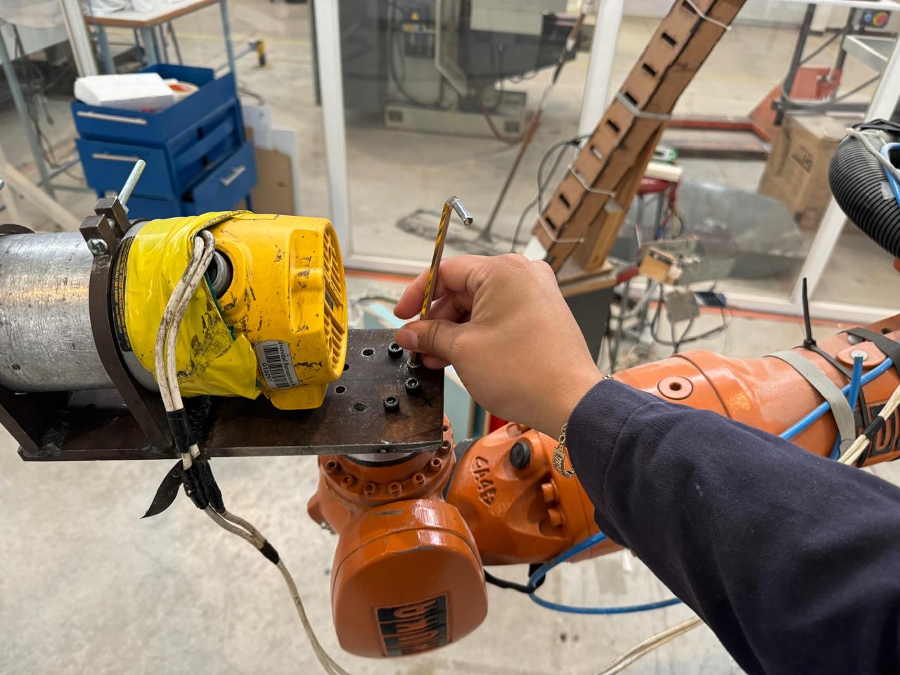
In this practice session, we will learn how to operate the KUKA robot. We'll start with a basic task: changing or mounting the tool. This involves securing it using screws and Allen keys.
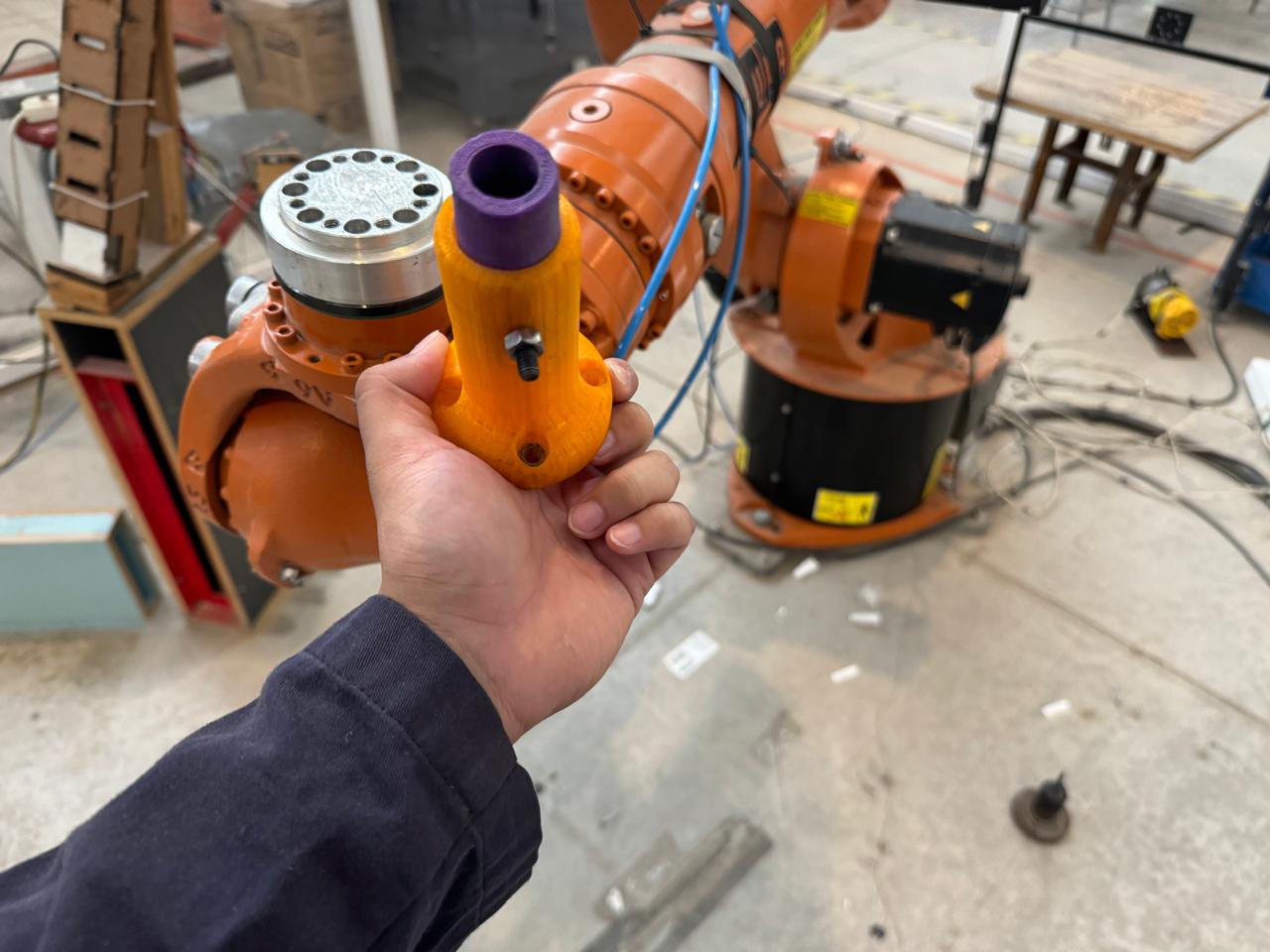
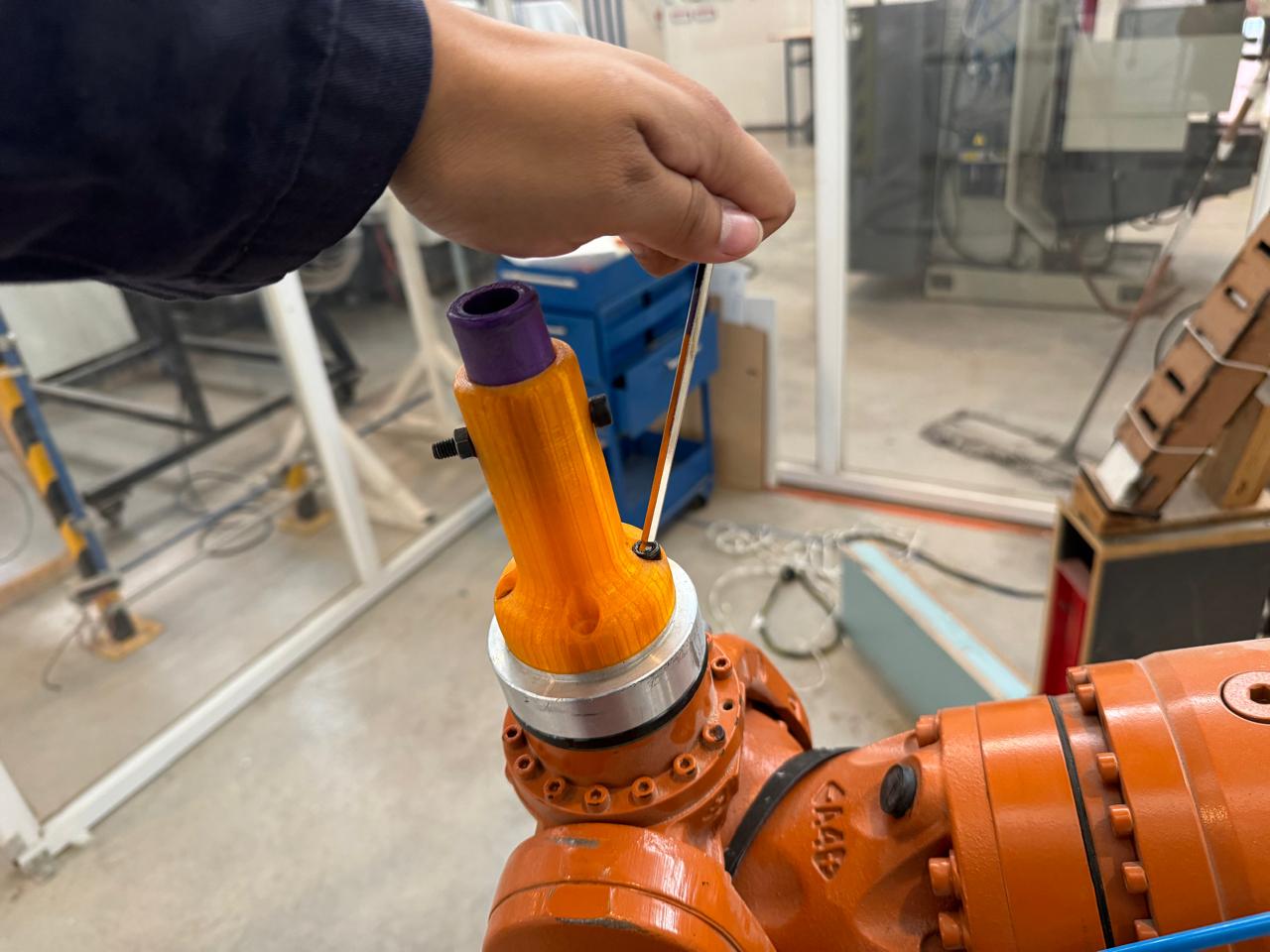
Once the tool is mounted, we will proceed to configure the Tool Center Point (TCP) for our tool, which in this case is a marker.
-
Access Configuration
- Menu > Configuration > Tool Calibration.
-
Select Tool
- Choose the tool or create a new one.
-
Define Calibration Method
- Select a method: 4 points, 6 points, XYZ 4 points.
-
Measure Points
- Move the tool to the indicated positions and save each point.
-
Confirm and Save
- Review the calculated values and save the TCP configuration.
-
Validate TCP
- Move the robot using the new TCP and verify its accuracy.
-
Final Adjustments
- Manually adjust if necessary and repeat validation.
- Setting Up the TCP: First, I set up the TCP for the marker. This means I calibrated and adjusted the position of the marker on the robot to ensure that the robot correctly recognizes where the marker is at all times.
- Movement Tests: After setting up the TCP, I performed some tests to make sure the robot recognized the marker's position correctly and could make precise movements. I conducted simple movements, such as linear and rotational motions, to verify the system's accuracy and consistency.
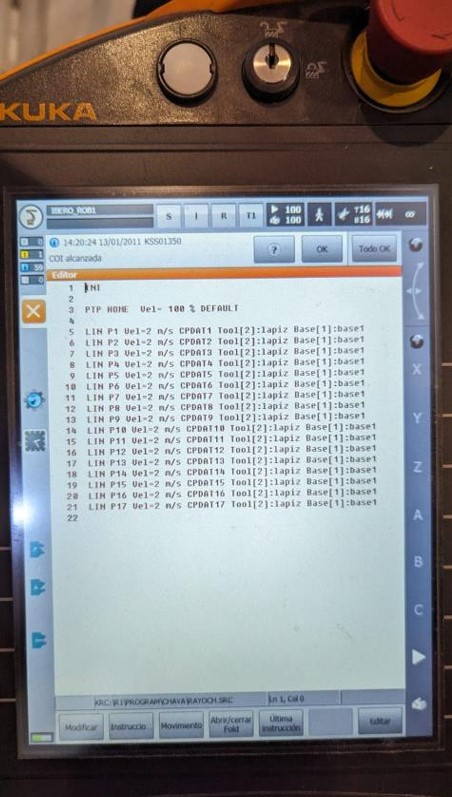
- Programming the Lightning-Shaped Figure: With the TCP for the marker configured and tested, I proceeded to program the lightning-shaped figure. This involved writing a motion control program to instruct the robot to move the marker through a series of points in space, following the desired lightning shape design.
- Point-by-Point Programming: I programmed the robot to move the marker point by point, following the shape of the lightning bolt. For this step, I used a printed design as a guide and performed only linear operations, as the figure was suited for it.
- Testing and Adjustments: Once the lightning-shaped figure was programmed, I conducted tests to ensure that the robot followed the desired path correctly and that the figure was drawn accurately. I made any necessary adjustments to ensure everything was perfect.
Point 1
Save Point
Point 2
After point 2 we repeat the procedure in each of the corners until the ray is completed.
final code
Robot Practice Steps - Part 2: Circular Movements
- Programming the Devil Emoji Figure: Once the robot with the marker is configured and tested, we proceed to program the devil emoji figure using circular movements. For this, we define circles using two points: the starting point and the endpoint.
- Programming Circles:
We program the robot to draw the circles that make up the devil emoji figure. Each circle is defined using two points: a starting point and an endpoint. This involves:
- Defining the coordinates of the starting point of the circle.
- Defining the coordinates of the endpoint of the circle.
- Programming the robot to move between these points, tracing an arc that forms a half-circle.
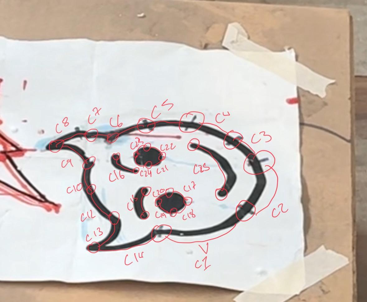
Each C has a beginning and an end, realizing that in this figure we would need to program 25 points as shown in the image
- Drawing the Figure: The robot executes the program and starts drawing the half-circles that form the devil emoji. Each half-circle is drawn using the specified two points, following the programmed instructions. This process is repeated for each section of the figure until the drawing is complete.
- Testing and Adjustments: Tests are conducted to verify that the robot draws the circles accurately and that the devil emoji figure is correctly formed. This includes:
- Ensuring that the half-circles are drawn in the correct position and with the appropriate size.
- Adjusting the coordinates of the starting and ending points as needed to improve the precision and appearance of the figure.
- Repeating tests and adjustments until the desired result is achieved.
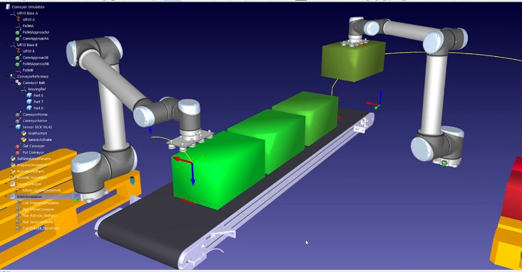
RoboDK: Virtualization and Robot Control

RoboDK is offline robot simulation and programming software that allows the virtualization of the workspace and the generation of trajectories for robots. This software facilitates the operation and control of the robots available in its catalog by importing .STL and .DXF files.
Main Features of RoboDK
- File Import: Allows the import of models in .STL and .DXF format for workspace virtualization.
- Trajectory Generation: Facilitates the creation of trajectories and robot programs that can be directly loaded into the robot controller.
- 3D Simulation: Provides a 3D simulation of the work environment, allowing visualization and optimization of trajectories before actual execution.
- Offline Programming: Enables robot programming without stopping production, which is ideal for industrial environments where downtime is costly.
- Compatibility with Multiple Robots: Supports a wide variety of robot brands and models, making it a versatile tool for different applications.
Note: In practice, we did not use RoboDK because it was not necessary for our specific project. However, it is mentioned as relevant information since it is a useful tool in robotics.