Networking and communications
Linked to the group assigment page
Communication Protocols Overview
Network and Communication Protocols in Embedded Systems
Embedded systems feature networking capabilities that allow them to connect to various networks or devices to exchange information or data for monitoring and control purposes. These systems utilize a variety of communication protocols to facilitate this interaction.
Common Communication Protocols
The most commonly used protocols include I2C, SPI, and UART. For broader range applications, higher-level network protocols such as Ethernet, Wi-Fi, and Bluetooth are also employed.
UART (Universal Asynchronous Receiver-Transmitter)
UART supports asynchronous serial communication between two devices using a transmitter (Tx) and a receiver (Rx). It operates by transmitting data one bit at a time on a single data line, utilizing start/stop bits to frame the data. Typically used for point-to-point communication over short distances, UART connects peripherals like GPS modules, Bluetooth modules, and sensors.
SPI (Serial Peripheral Interface)
SPI is a synchronous serial communication interface used for full-duplex communication between one master and one or more slave devices. It requires four lines: MISO (Master In Slave Out), MOSI (Master Out Slave In), SCK (Serial Clock), and SS (Slave Select). SPI operates under a master-slave architecture, where the master initiates communication by generating clock pulses and selecting slaves, allowing for simultaneous data transmission and reception at high speeds. It is commonly used with memory devices, display controllers, and sensors within integrated systems.
I2C (Inter-Integrated Circuit)
I2C is a multi-master/slave communication protocol that enables devices to interact over a bus using two wires: SDA (Serial Data Line) and SCL (Serial Clock Line). In this setup, the master controls the bus and handles communications with the slaves. It supports bidirectional data transfer and allows multiple devices to share the same bus, making it ideal for connecting low-speed peripherals like sensors, EEPROMs, and digital IO. Its primary benefits include simplicity, requiring fewer pins, and the ability to connect multiple devices on the same bus.
application
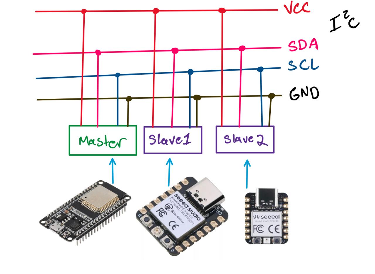
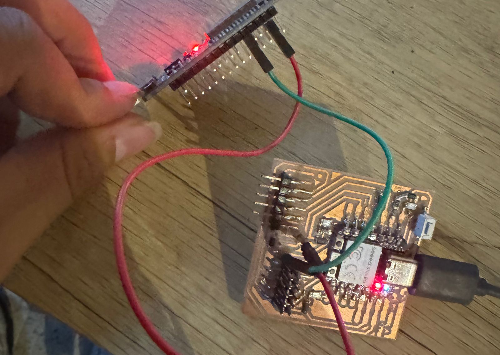
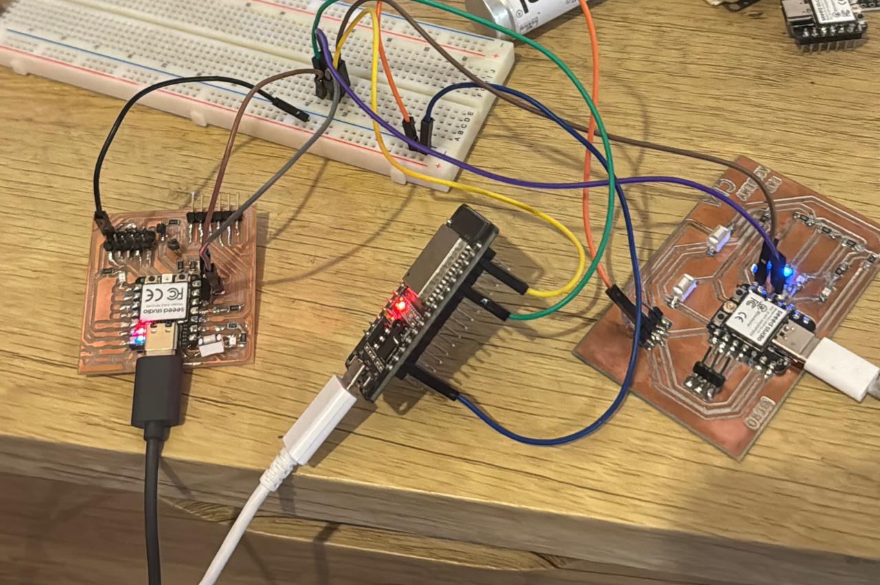
For my week I incorporated an i2c system which consists of data exchange for turning on LEDs. between 1 esp 32, a xiao rp2040 and a xiao esp32
Setting Up I2C Communication with ESP32 as Master
To set up an I2C communication where the ESP32 acts as the master and the Xiao RP2040 and Xiao ESP32 as slaves, I began by connecting the SDA (Serial Data Line) and SCL (Serial Clock Line) pins from the ESP32 to the corresponding pins on both Xiao devices.
In configuring the ESP32, I programmed the necessary functions to initiate and manage the I2C communication, sending data to the slave devices and receiving their responses. I assigned unique I2C addresses to both the Xiao RP2040 and Xiao ESP32 so that I could address each one individually. This allows me to effectively control multiple devices and clearly differentiate between the commands sent and the data received from each slave.
Additionally, I made sure that the code on the ESP32 properly managed interactions with multiple slaves, using their addresses to communicate specifically and coordinatedly with each device.
Principal sketch
Setting Up I2C Communication: ESP32 as Master
Steps for I2C Setup
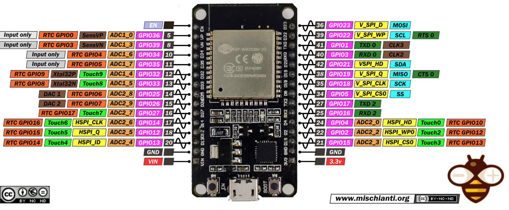
- Identifying Pins:
- On my ESP32, I located the SDA and SCL pins, typically pin 21 for SDA and pin 22 for SCL.
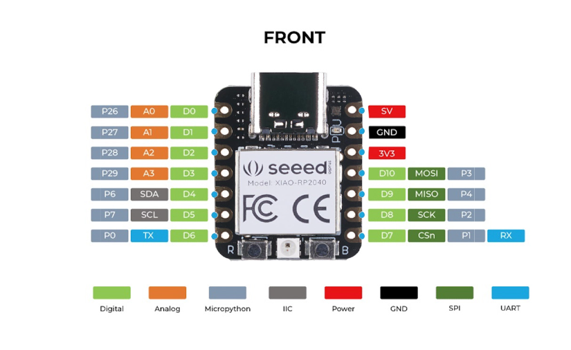
- On the Xiao RP2040 and Xiao ESP32, I also identified the corresponding pins marked for SDA and SCL.
- Connecting Pins:
- I connected the SDA pin of my ESP32 to the SDA pin of the Xiao RP2040.
- I connected the SCL pin of my ESP32 to the SCL pin of the Xiao RP2040.
- I repeated the same process for the Xiao ESP32, ensuring that the SDA and SCL of the ESP32 were connected to the SDA and SCL pins of the Xiao ESP32.
- Slave Configuration (Xiao RP2040 and Xiao ESP32):
I assigned a unique I2C address to each Xiao, setting them up to act as slaves. This involved programming each device to respond to master requests and handle data transmission and reception.
		// I2C Slave Device Addresses
		const int firstSlaveAddress = 0x04;
		const int secondSlaveAddress = 0x05;
- Coding:
I wrote code on the ESP32 to manage communication, including functions to send and receive data to and from each slave using their unique I2C addresses.
On the Xiaos, I programmed the necessary logic to process data received from the master and send the appropriate response.
- Testing:
Finally, I tested the complete system to ensure that communication between my ESP32 and the Xiaos was functioning correctly. I checked the integrity of the data sent and received and made adjustments to the configuration to optimize communication.
ESP32 Master
#include <Wire.h>

// Pin definitions and constants
const int localLedPin = 2; // Pin for the local LED
const int ledOnCommand = 1; // Command to turn on LED on I2C devices

// I2C Slave Device Addresses
const int firstSlaveAddress = 0x04;
const int secondSlaveAddress = 0x05;

void setup() {
  pinMode(localLedPin, OUTPUT); // Set the LED pin as output
  Wire.begin();                 // Start the I2C bus as master
  Serial.begin(115200);         // Start serial communication at 115200 bps
}

void loop() {
  controlLocalLed(true);        // Turn on the local LED
  sendI2CCommand(firstSlaveAddress, ledOnCommand);  // Send command to the first slave
  sendI2CCommand(secondSlaveAddress, ledOnCommand); // Send command to the second slave
  controlLocalLed(false);       // Turn off the local LED
}

// Function to control the state of the local LED
void controlLocalLed(bool turnOn) {
  digitalWrite(localLedPin, turnOn ? HIGH : LOW);
  delay(1000); // 1 second delay
}

// Function to send a command to an I2C device
sendI2CCommand(int address, int command) {
  Wire.beginTransmission(address); // Start transmission to the specified address
  Wire.write(command);             // Send the command
  Wire.endTransmission();
  delay(1000); // 1 second delay
}
RP2040 Slave
		#include <Arduino.h>
		#include <Wire.h>

		constexpr uint8_t ledPin = 1; // Pin for the built-in LED
		constexpr uint8_t i2cAddress = 0x05; // I2C address of this device
		volatile int receivedByte = 0; // Stores the received byte

		void setup() {
		  pinMode(ledPin, OUTPUT);  // Configure the built-in LED as output
		  Wire.begin(i2cAddress);   // Set this device's I2C address
		  Wire.onReceive(onI2CReceive); // Set the I2C receive function
		  Serial.begin(115200);     // Start serial communication at 115200 bps
		}

		void loop() {
		  delay(200);  // Passive wait for I2C commands
		}

		void onI2CReceive(int byteCount) {
		  while (Wire.available() > 0) {
			receivedByte = Wire.read();  // Read the received byte
			if (receivedByte == 1) {
			  digitalWrite(ledPin, HIGH);   // Turn on the LED
			  delay(1000);                  // Keep the LED on for 1 second
			  digitalWrite(ledPin, LOW);    // Turn off the LED
			}
		  }
		}
XIAO-ESP32 Slave
			#include <Arduino.h>
			#include <Wire.h>

			constexpr uint8_t ledPin = D2; // Pin for the LED
			constexpr uint8_t i2cAddress = 0x04; // I2C address of this device
			volatile int receivedByte = 0; // Stores the received byte

			void setup() {
			  pinMode(ledPin, OUTPUT);  // Configure the LED pin as output
			  Wire.begin(i2cAddress);   // Set this device's I2C address
			  Wire.onReceive(onI2CReceive); // Set the I2C receive function
			  Serial.begin(115200);     // Start serial communication at 115200 bps
			}

			void loop() {
			  delay(200);  // Passive wait for I2C commands
			}

			void onI2CReceive(int byteCount) {
			  while (Wire.available() > 0) {
				receivedByte = Wire.read();  // Read the received byte
				if (receivedByte == 1) {
				  digitalWrite(ledPin, HIGH);   // Turn on the LED
				  delay(1000);                  // Keep the LED on for 1 second
				  digitalWrite(ledPin, LOW);    // Turn off the LED
				}
			  }
			}
notes
I tried to communicate the esp32 and xiao esp32 through bluetooth but I had complications with the libraries, that's why I better leave it with i2c, in addition to that failure. I decided to connect these microcontrollers through another i2c to a Rapsberry 3
In my I²C communication project, I have decided not to add additional pull-up resistors to the SDA and SCL lines for the following technical reasons:
1. Internal Pull-up Resistors
Both the RP2040 board and the Xiao ESP32 are designed with internal pull-up resistors on the I²C pins (SDA and SCL). These internal resistors are generally sufficient for many standard applications and allow reliable communication between the devices connected on the I²C bus.
2. Integrated External Pull-up Resistors
In addition to the internal resistors, my PCB RP2040 design includes external pull-up resistors on the SDA and SCL lines. These additional resistors are sufficient to ensure that the I²C lines remain high when not actively pulled low by a device, thus ensuring signal integrity.
3. Avoiding Redundancy and Potential Conflicts
Adding more pull-up resistors could be redundant and, in some cases, counterproductive. Too many pull-up resistors can cause the SDA and SCL lines to not behave correctly due to excessive pull-up current. This can hinder I²C communication and potentially damage the devices.
4. Satisfactory Design and Testing
The current design has been tested and validated, demonstrating that I²C communication is stable and reliable with the integrated pull-up resistors (both internal and external). No data transmission issues or communication failures have been identified, confirming that the existing pull-up resistors are adequate for this project.
pin out Raspberry pi 3b
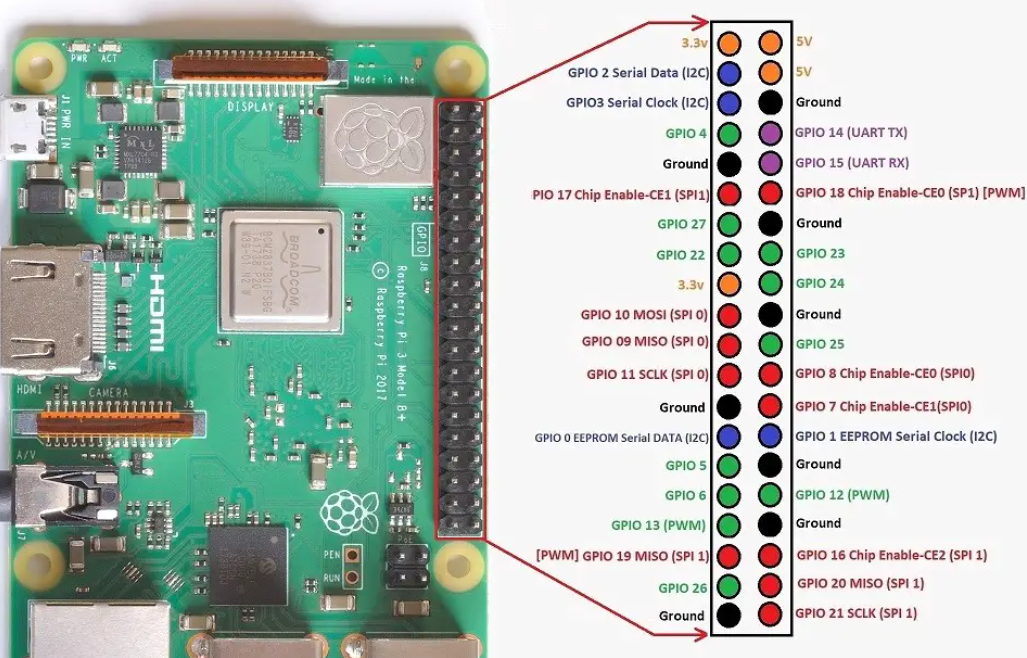
Pin Identification
First, I identified the I2C pins on both devices. On my Raspberry Pi 3B, the pins are GPIO 2 for SDA and GPIO 3 for SCL.
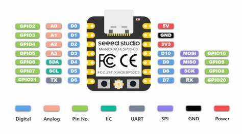
On the ESP32 DevKit V1, I assigned GPIO 21 for SDA and GPIO 22 for SCL.
Connecting the SDA and SCL Pins
I connected a jumper wire between the GPIO 2 (SDA) on the Raspberry Pi and GPIO 21 (SDA) on the ESP32.
Then, I connected another wire between GPIO 3 (SCL) on the Raspberry Pi and GPIO 22 (SCL) on the ESP32.
Establishing Common Ground
To ensure that both devices work correctly together, I connected a wire between any ground pin (GND) on the Raspberry Pi and a ground pin (GND) on the ESP32.
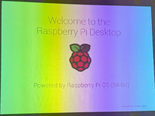
Welcome Screen of Raspberry 3 Pi OS
When I started my Raspberry Pi, the welcome screen of the Raspberry Pi Desktop appeared, indicating that it had been configured or rebooted successfully with the Raspberry Pi OS ready for use. This suggests that an important setup or update stage has been completed.
Package Installation
I continued with the installation of additional packages or updates on the Raspberry Pi. This step is crucial after making changes to the system configuration or before starting a new project.

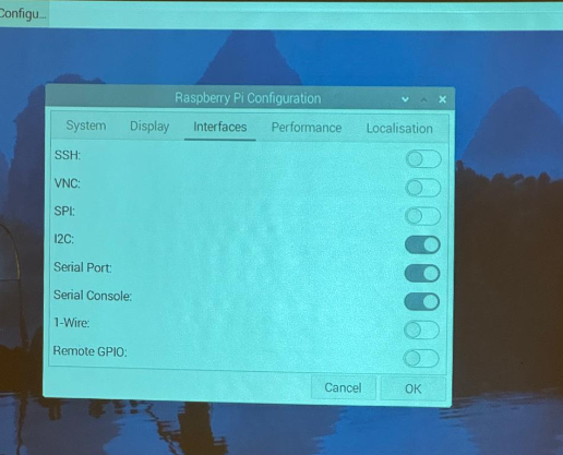
Raspberry Pi Interface Configuration
I accessed the Raspberry Pi configuration menu to adjust various system interfaces such as SSH, VNC, SPI, I2C, etc. This adjustment is essential for enabling or disabling protocols and ports necessary for my hardware projects.
code
		# Import necessary libraries
		import smbus2
		import time

		# Define the I2C bus number (usually 1 for Raspberry Pi)
		bus_number = 1
		# Define the I2C address of the device
		device_address = 0x04

		# Initialize the I2C bus
		bus = smbus2.SMBus(bus_number)

		def read_integer_from_i2c():
			try:
				# Read a byte from the I2C bus, switch to read_i2c_block_data if multiple bytes are sent
				data = bus.read_byte(device_address)
				print("Data received:", data)
			except Exception as e:
				print("Error reading from I2C bus:", e)

		while True:
			read_integer_from_i2c()
			time.sleep(1)  # Delay of 1 second between reads
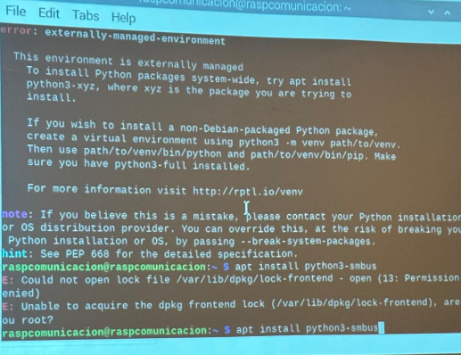
Error Handling and APT Commands
During the process, I had to handle some errors related to externally managed environments and perform installations with APT (Advanced Package Tool). I encountered a specific permissions issue, which reminded me of the need to use elevated privileges (sudo).
Creation of a Virtual Environment
To ensure the installation of the necessary libraries for my project, I created a virtual environment. This helped me manage dependencies without affecting the global Python system installed on my Raspberry Pi.
Installation of smbus2 and Issues with Time Module
I successfully installed the smbus2 library for interfacing with I2C devices within the virtual environment. I also tried to install the time module, but faced an error since time is an integrated module in Python and does not require an external installation.
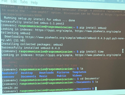
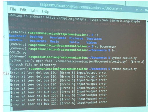
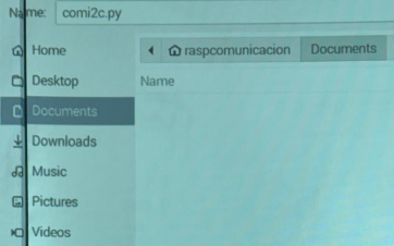
Failed Script Execution and I2C Communication Problems
Finally, I saved and tried to execute the com2ic.py file from the terminal. However, I faced issues in the I2C communication with the ESP32 device, resulting in several errors displayed in the terminal.