Electronics Production
Linked to the group assigment page
About PCB
One of the most prominent aspects of printed circuit boards (PCBs) is their function as electrical connectors between electronic components through traces and pads. These boards, constructed with layers of various laminated materials, facilitate the routing of signals and power between physical devices. Soldering acts as both an electrical conductor and a strong mechanical adhesive. Additionally, there are various materials for PCBs, each with its specific characteristics. For example, FR4, the most commonly used, employs fiberglass as a base. It is essential to understand key terms related to PCBs, such as "annular ring," "design rule check (DRC)," and "solder mask," among others, to comprehend their design and fabrication.
Tips for soldering like a pro
- Essential Tools: Use a quality soldering iron with a clean and fine tip for efficient heat transfer. You'll also need solder flux, quality solder, and anti-static tweezers for handling components.
- Temperature Control: Adjust the soldering iron temperature according to the type of component and the size of the copper traces on the PCB. Too high a temperature can damage components, while too low a temperature can result in weak joints.
- Proper Preparation: Clean the copper traces and pads with isopropyl alcohol and a soft brush before soldering to remove any residue. This ensures better solder adhesion.
- Use of Solder Flux: Apply a small amount of solder flux to the areas to be soldered to improve solder flow and adhesion. This helps prevent solder bridges and ensures solid connections.
- Soldering Technique: Keep the soldering iron in contact with the pad and component for a few seconds to allow heat to distribute evenly. Then, apply solder to the point of contact until the solder completely covers the pad and component.
- Avoiding Overheating: Avoid heating components for too long to prevent damage. Additionally, avoid applying too much solder, as it can cause short circuits between nearby traces.
- Inspection and Cleaning: After soldering, visually inspect all connections to ensure they are clean and shiny. Clean any excess solder or residue with isopropyl alcohol and a soft brush.
- Practice and Patience: Soldering on PCBs requires practice to master. Start with simple projects and practice regularly to improve your soldering skills. Be patient and don't be discouraged by initial mistakes, as practice will help you improve over time.
personal learning
During this week, we will be creating a PCB based on a provided PNG file. It's simply a matter of putting theory into practice, programming the machine regarding speeds, axes, among other settings, as will be demonstrated in the following visual aids. It's worth mentioning that a ROLAND SRM-20 machine will be used for this purpose.
PCB steps
For making the files compatiblle for the machine (.rml) we will use the software called Mods.
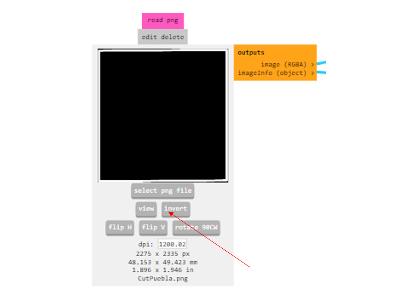
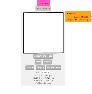
In this first video, we can see the steps for setting up the program for PCB engraving.
For cutting, it's the same process, except that for the PNG, we will add the invert button and we changed de tool.
Steps for the machine
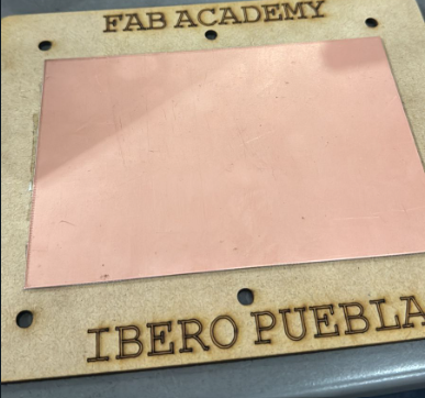
1. Safety bed
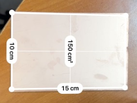
In this step, we will use knowledge previously seen in week 3 to cut our safety bed on the laser CNC.
Then, we measure and adhere a copper plate.
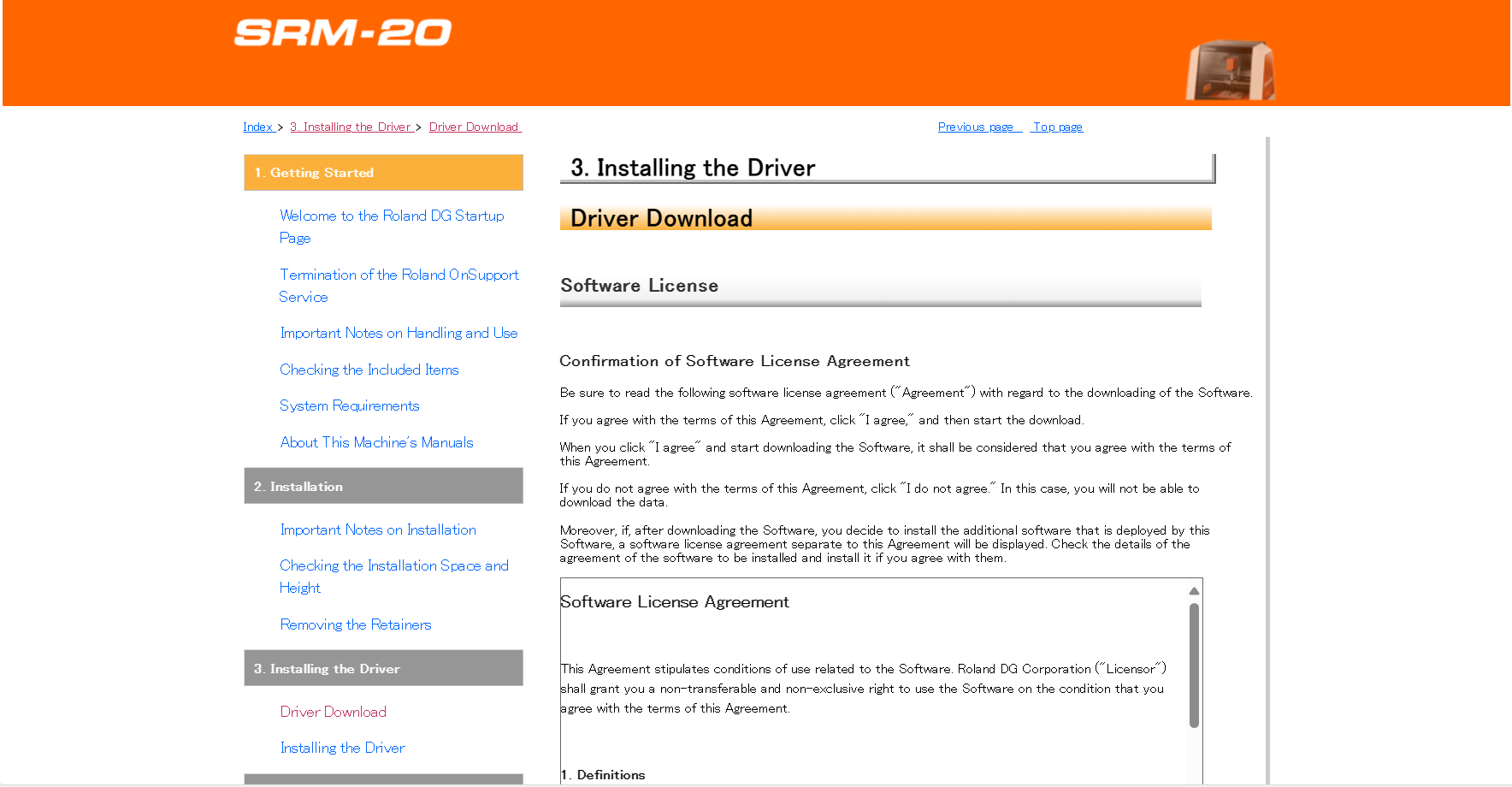
2. Program and Driver
To use the machine, we need to install a program and a driver.

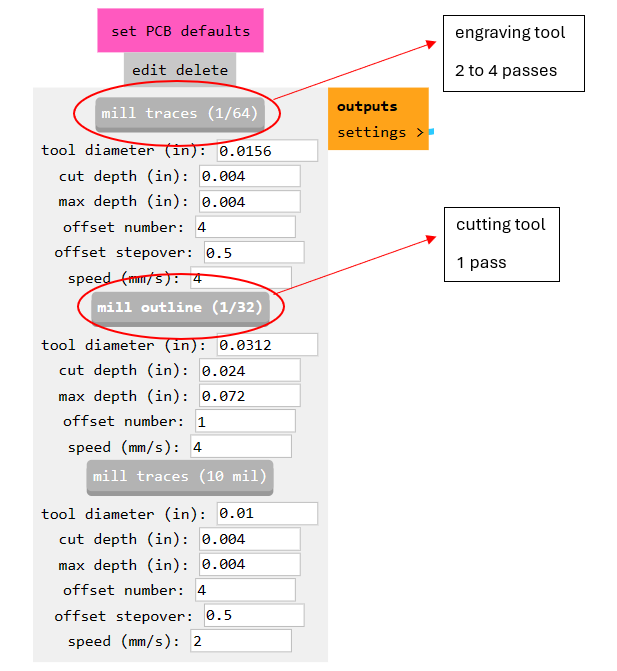
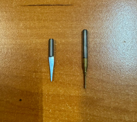
3. Identify tools
We are going to use a 15 degree V-bit for engraving and a 0.8 mm end Mill for cutting.
The tool on the left side is the engraver and the tool on the right side is the cutter that we will be using.
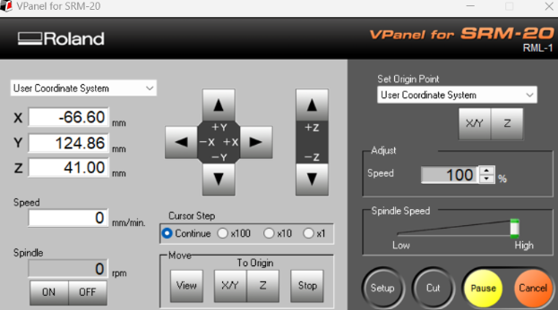
4. Sofware SRM-20
You have the option to manipulate the axis movement simply by clicking on the directional arrows. Additionally, you can designate the X/Y and Z origins from the options situated at the top right corner of the screen. It's also possible to toggle the spindle on or off as needed. Furthermore, you can navigate precisely to the origin point located at the bottom center of the screen. Adjustments to the approach speed can be made in the center of the screen When it comes to loading files and commencing cutting or engraving tasks, you'll find the necessary tools within the "Cut" section. Here, you can upload the engraving file to finalize the process, and if required, delete any previous engraving before adding the cutting file.
5.Calibrate, Engraving and Cut
First, secure the MDF with copper on the machine. Then, open the software and connect it to the Roland. Place the engraving tool and calibrate the X/Y axis around one centimeter from the bottom left corner. Next, lower the Z-axis near the board, adjusting the focus speed if necessary. Loosen the tool and allow it to touch the board before tightening it again. Save the X/Y/Z coordinates and move the tool upwards for safety. Finally, initiate the engraving process.
Once the process is complete, we proceed to vacuum up the remaining debris.

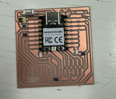
We change the tool to the cutting one and repeat the previous steps. The PCB should look like the one in the image.
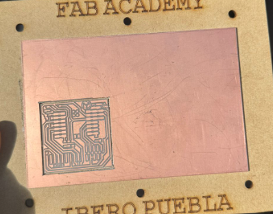
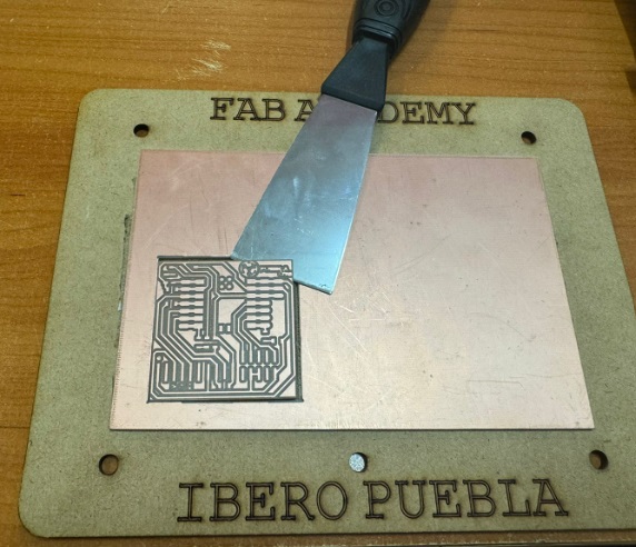
we remove the cut part. After everything is done, check the copper plate and tracks.
6. Components and soldering
First, we identify the components that we will solder.
Components:
| Qty | Description | Image |
|---|---|---|
| 1 | XIAO ESP32C3 | 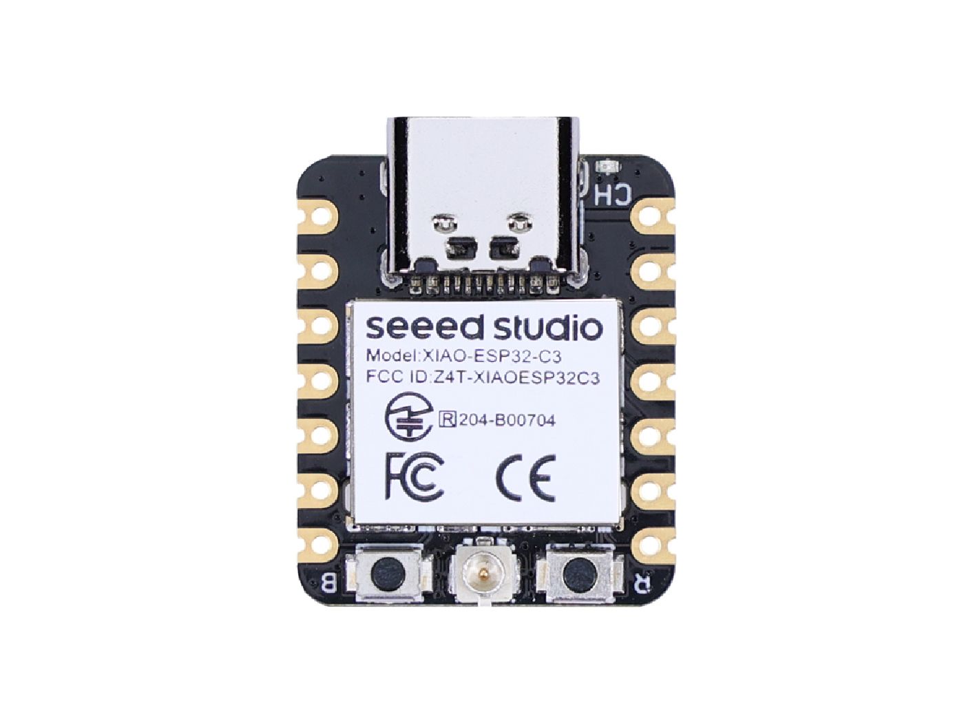 |
| 4 | 820 ohms resistor | 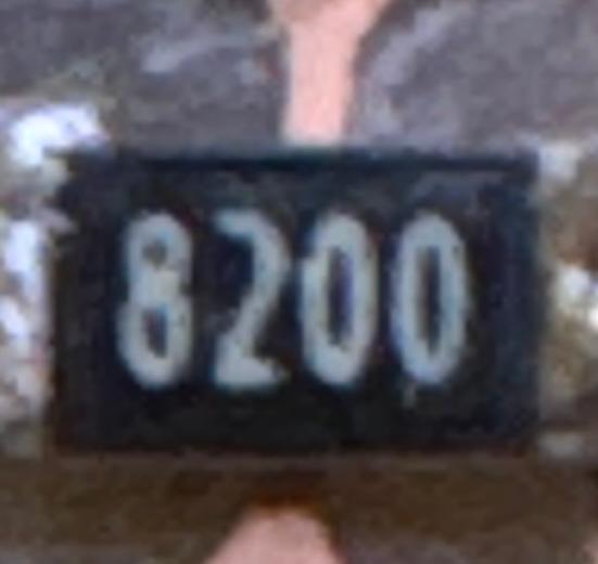 |
| 2 | 2.4 kΩ (242) resistor | 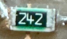 |
| 4 | Leds | 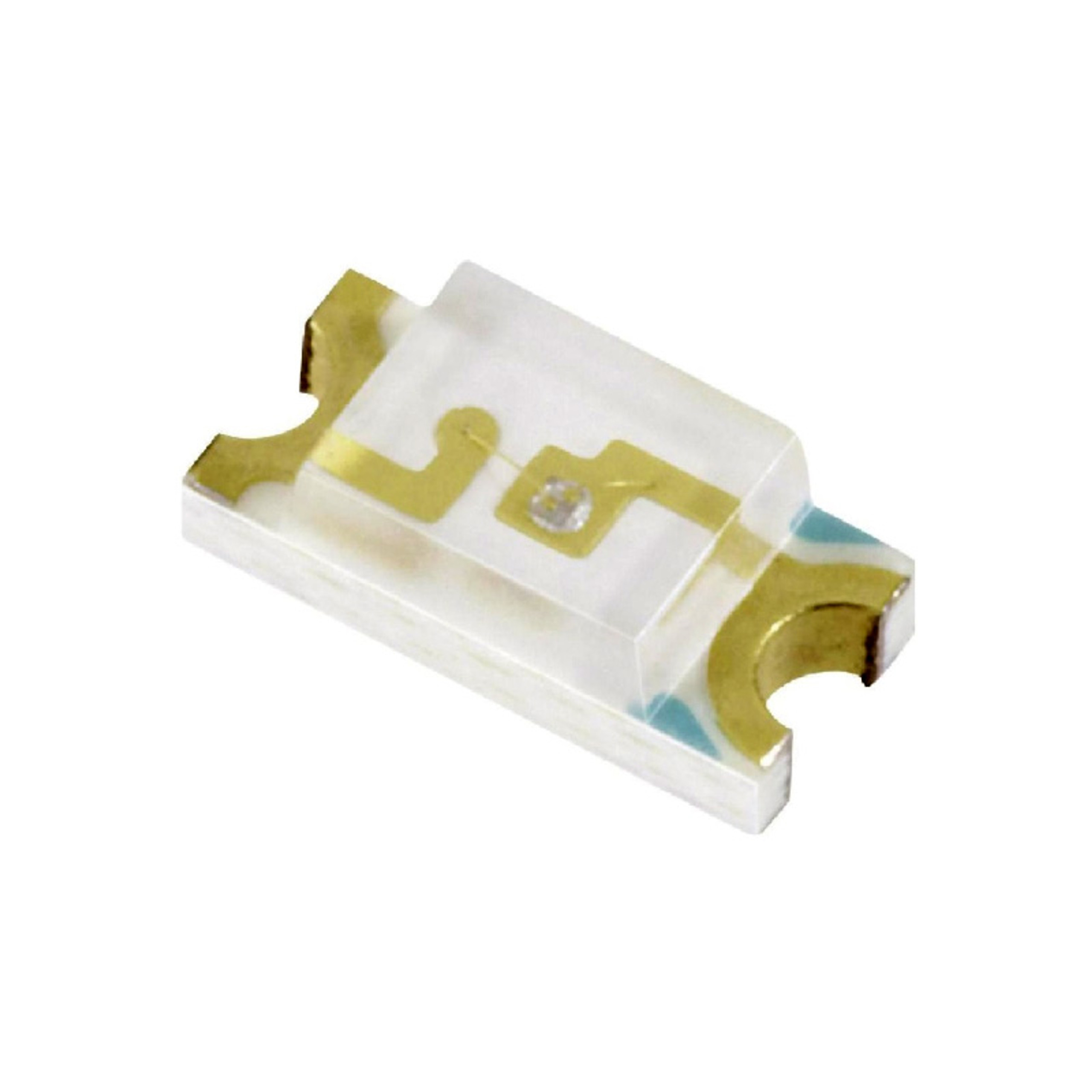 |
| 2 | push button | 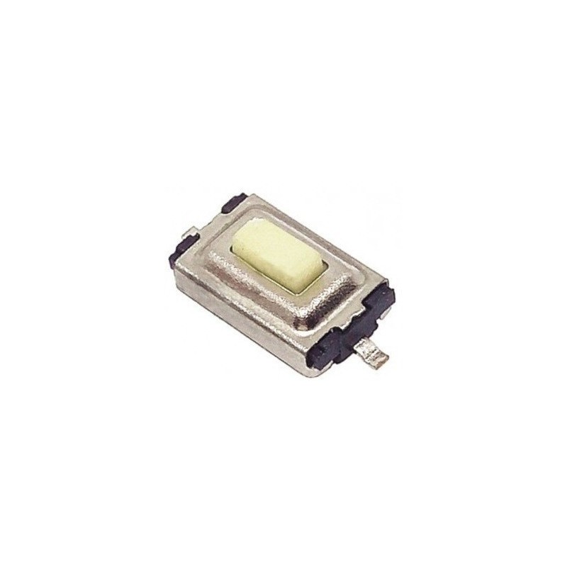 |
| 1 | 4-pin Right-Angle SIL Headers | 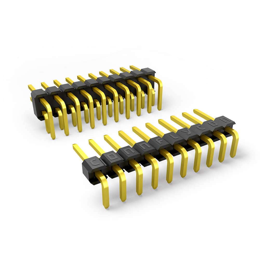 |
| 1 | 3-pin Right-Angle SIL Headers | |
Materials:
| Qty | Description | Image |
|---|---|---|
| 1 | Roll of tin for soldering | 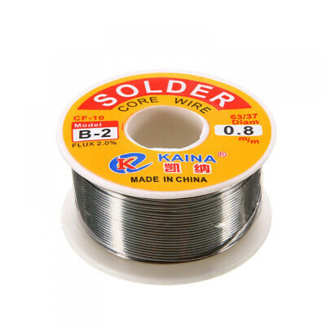 |
| 1 | Soldering iron | 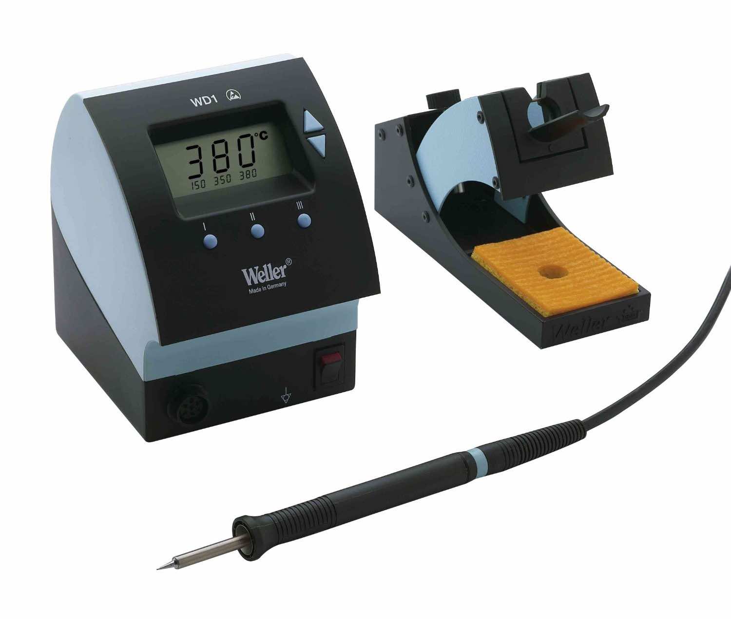 |
| 1 | Tweezers | 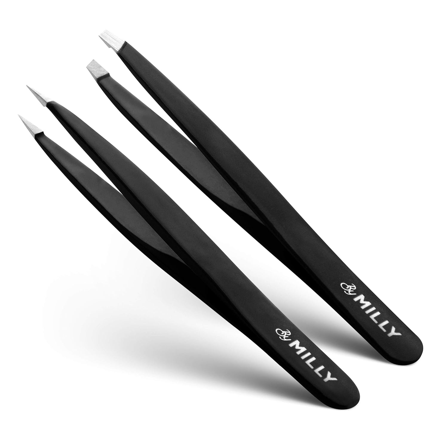 |
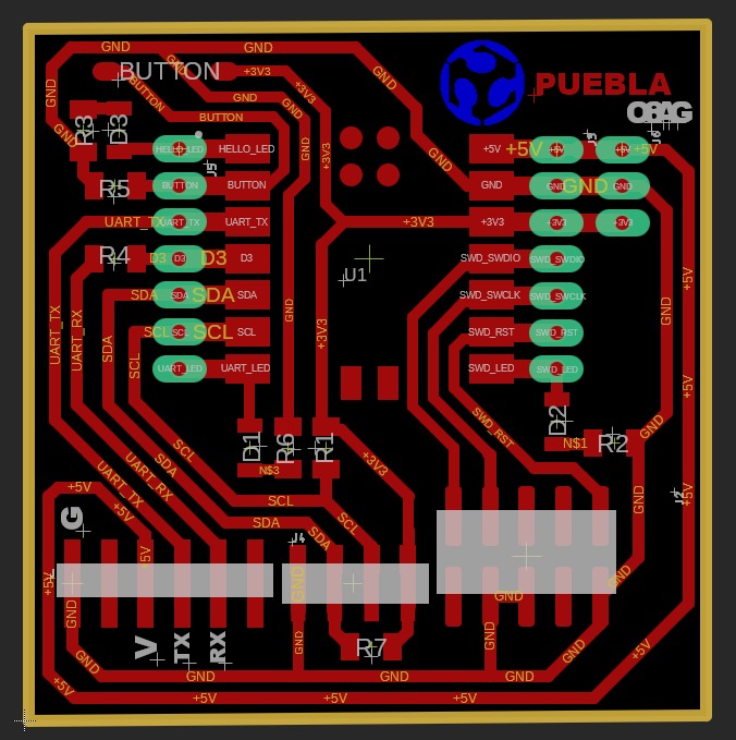
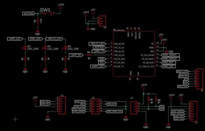
Schematics and Reference image for connections
Soldering
identification of components and their location
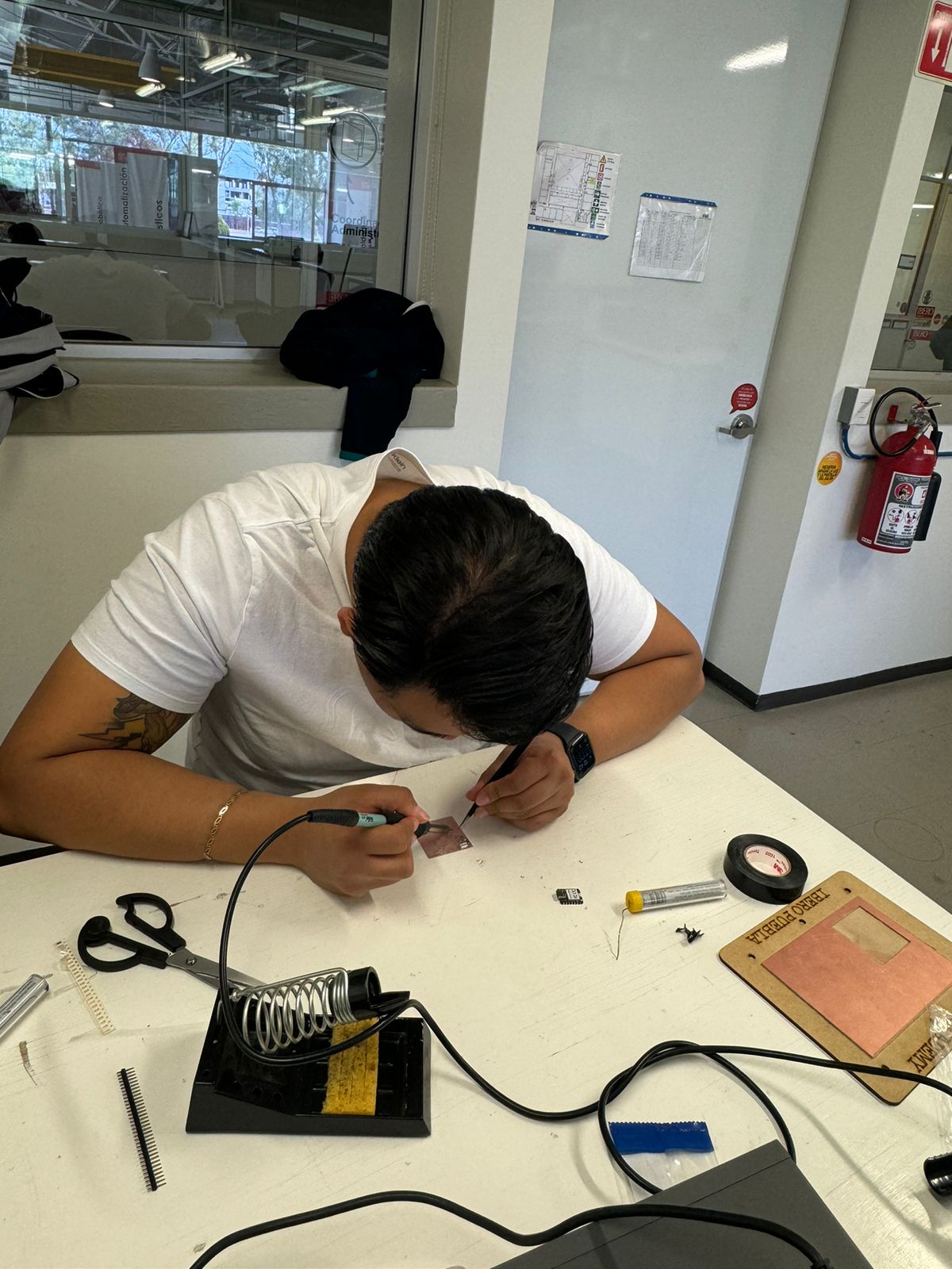
We proceed to solder.
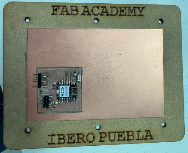
So that it finally looks like this.
7. Programming
Steps
- Open the Arduino software on your computer.
- Go to the "File" option in the menu bar and select "Preferences."
- A window will open. In the "Additional boards manager URLs" field, paste the following link: https://github.com/earlephilhower/arduino-pico/releases/download/global/package_rp2040_index.json
- Click "OK" to close the preferences window.
- Now, go to the "Tools" option in the menu bar and select "Board." Then, choose "Boards Manager."
- In the search box within "Boards Manager," type "RP2040."
- You should see an option corresponding to the "earlephilhower/arduino-pico" package. Click the "Install" button next to this option to install support for the RP2040 board in Arduino.
- Once the installation is complete, close the "Boards Manager" window.
- Now, go back to the "Tools" option in the menu bar. Select "Board" and choose your RP2040 board from the list of available options.
- Next, select the port to which your RP2040 board is connected in the "Port" option within the "Tools" menu.
- Now you are ready to upload your own code to the RP2040 board! Write or open the code you want to upload to the board.
- Finally, click the "Upload" button (right arrow) at the top left of the Arduino window to compile and upload your code to the RP2040 board.
.rml)