10. Mechanical design & machine design
This week was entirely dedicated to team work to create a CNC of our choosing. My team opted for a CNC sewing machine, in which we could embroider figures or, in any case, letters. Each member contributed individually, and in my case, it was the design. For this purpose, I first made a sketch of what I wanted to achieve and thought that 3 mm MDF would be sufficient. However, as we tested the pieces, it required recalculating the design and remaking many of the parts. We even ended up placing up to 3 laser-cut boards with the same shape placed together. However, upon seeing the finished design, although it seemed functional, it didn't quite meet the FabAcademy standard. As we noticed that we couldn't achieve a 90° angle, I decided to incorporate metal angles into the design using a drill. But in doing so, we realized that the structure wasn't strong enough. We then cut a piece of MDF in a way that wouldn't collapse the structure inward. Once all this was calculated, we decided to remake all the pieces again, but this time using a 15 mm MDF in the CNC Router to ensure a stronger structure. (The final files are available on our team's group page) .
What did I do?
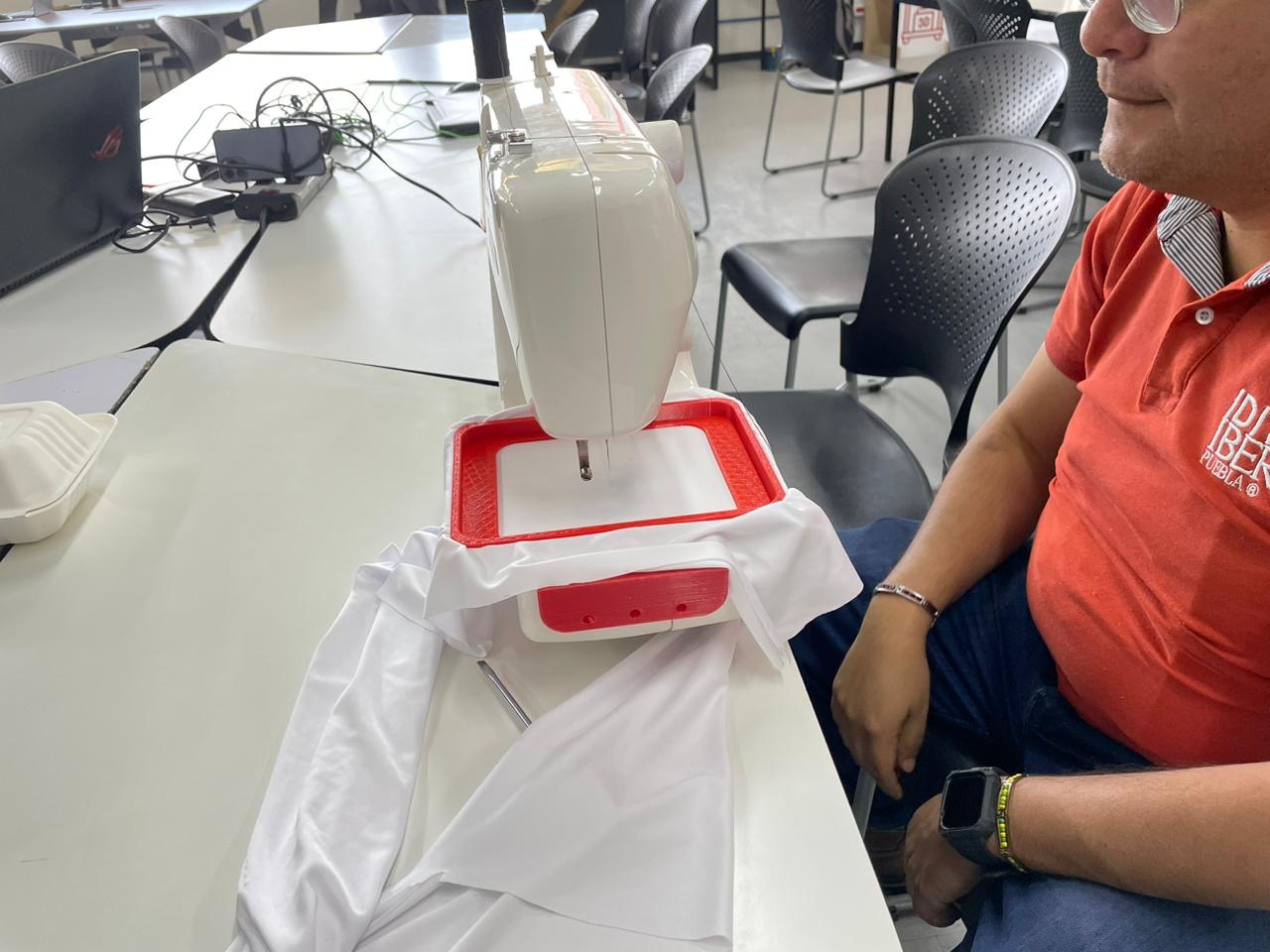
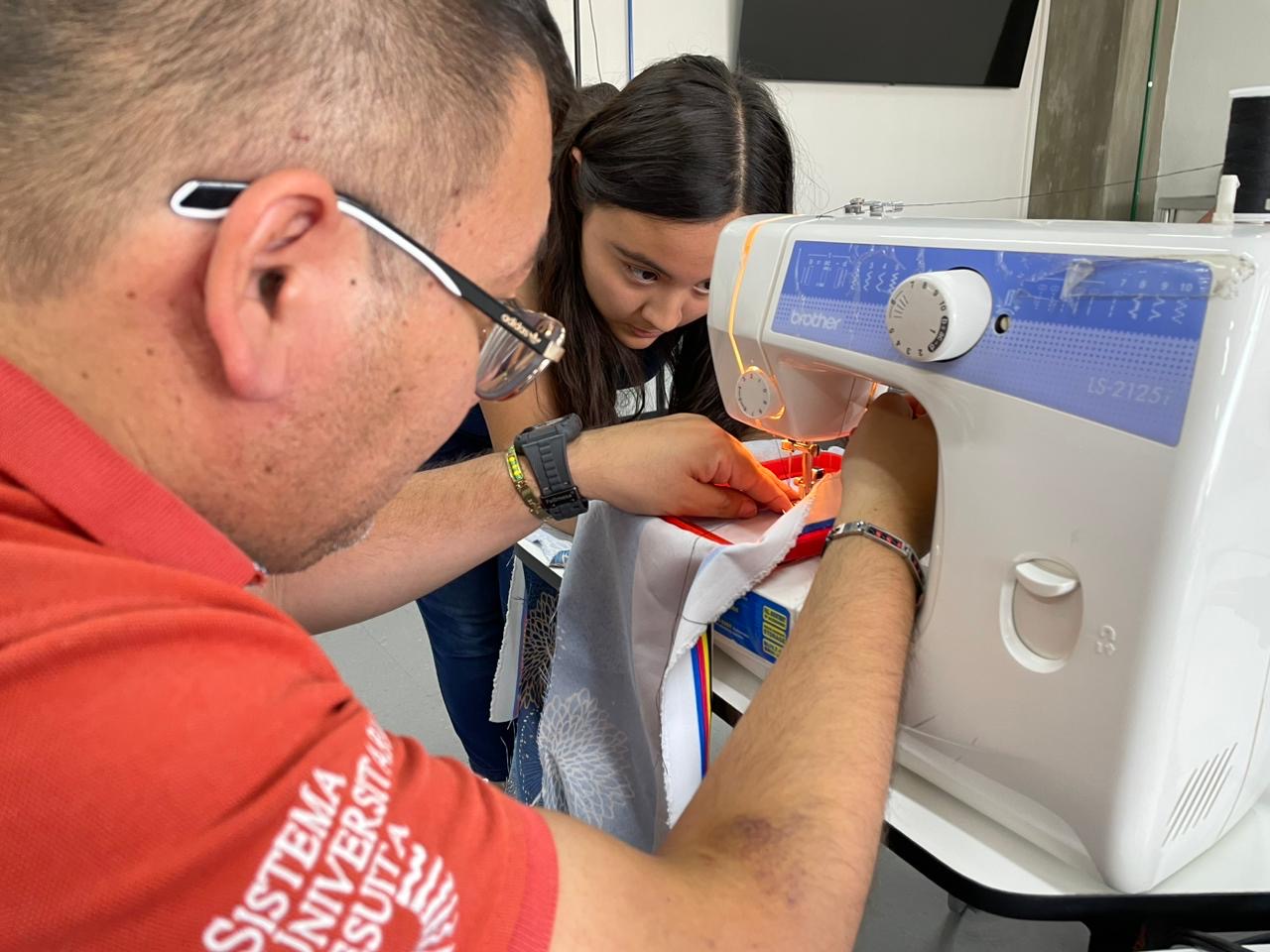
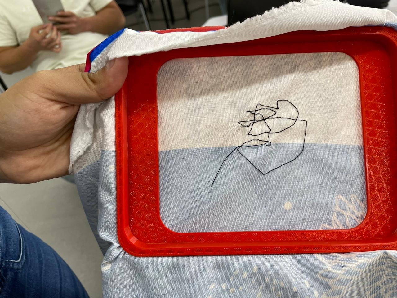
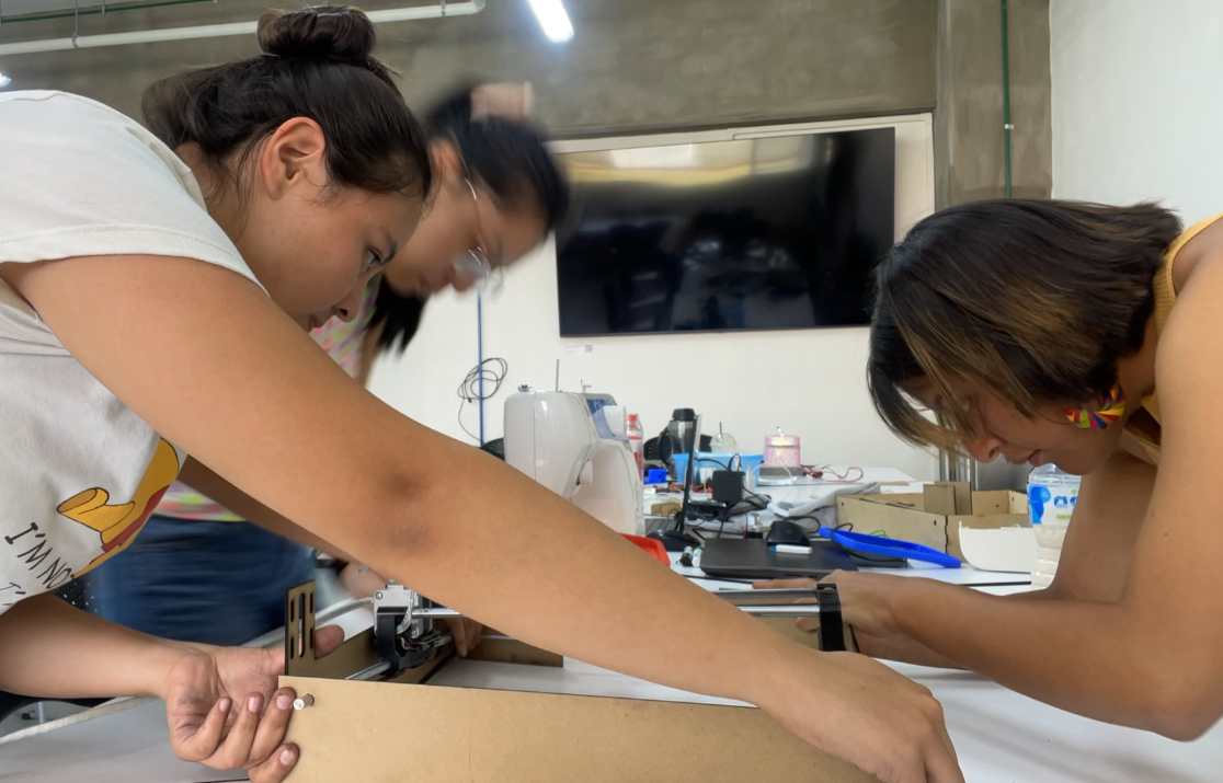
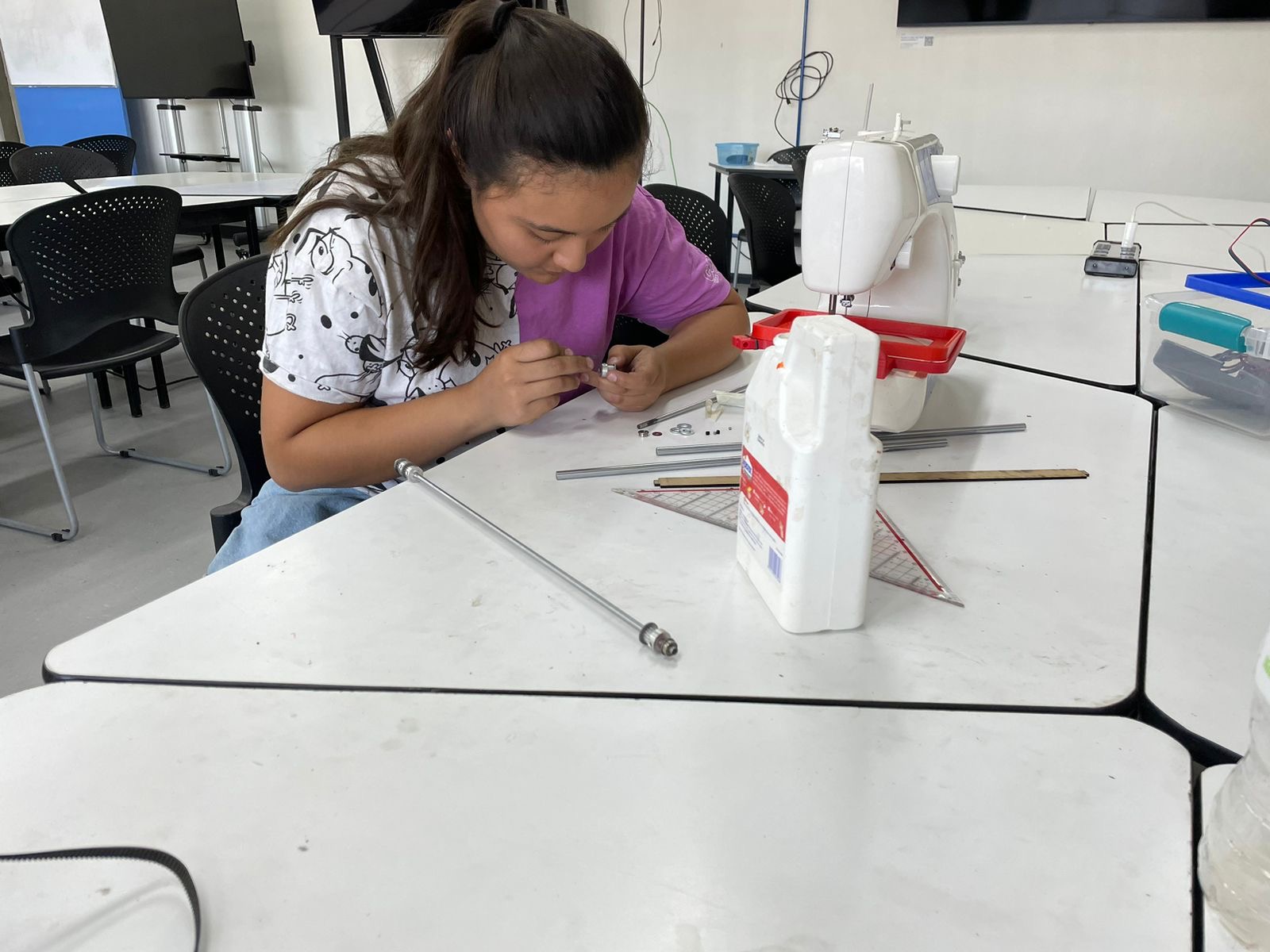
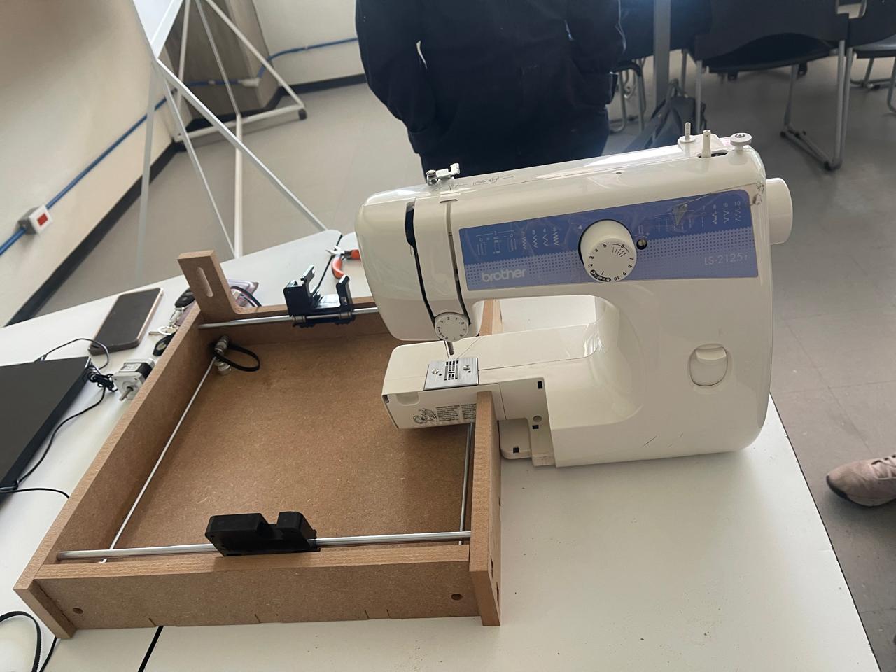
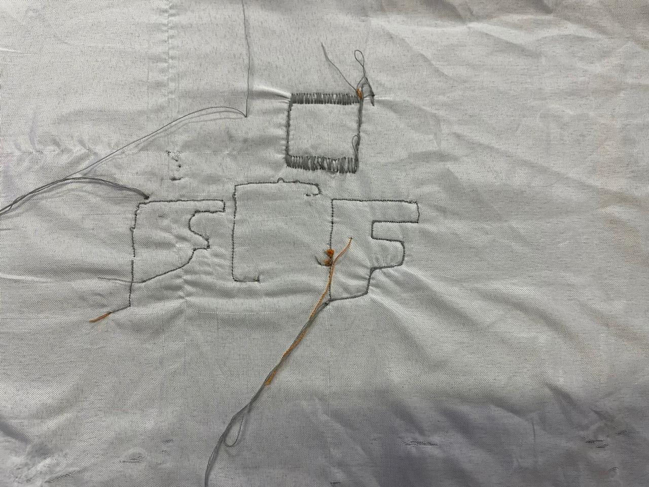
The first step we had to check was to see if, upon turning on the sewing machine and placing the fabric on the sewing bed, I could manually move it in different directions to sew and thereby determine if the project was viable or not. As can be seen in the images, we first placed the fabric on the sewing bed, then sewed in different directions, and finally, there is an image demonstrating that it does indeed work.
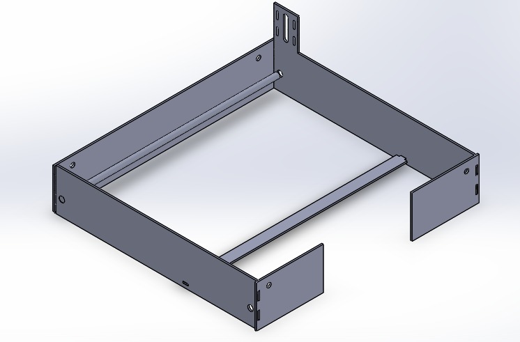
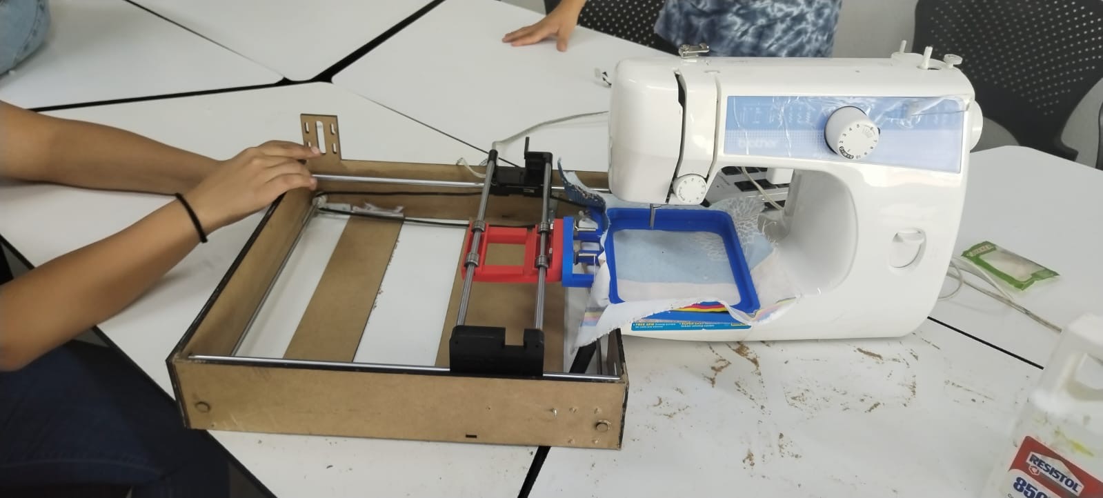
The next step to complete the task assigned to me was to think about how to design the movement mechanism. My idea was that the sewing machine had to be inside the structure, and for that reason, I created the following design.
When designing the first prototype, I thought that 3 mm MDF would be sufficient, so once we had the pieces seen at the top, they were laser-cut and then assembled.
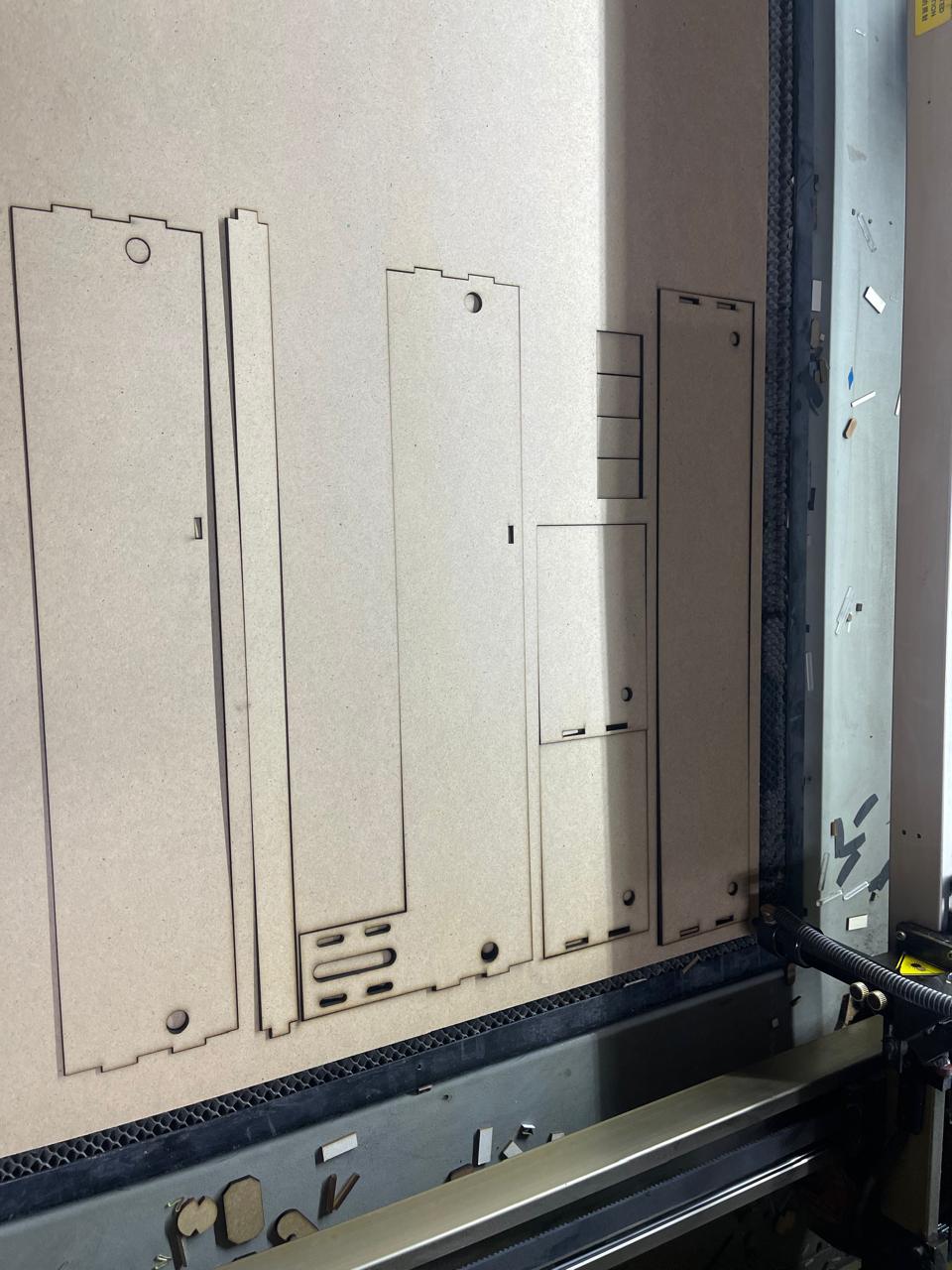
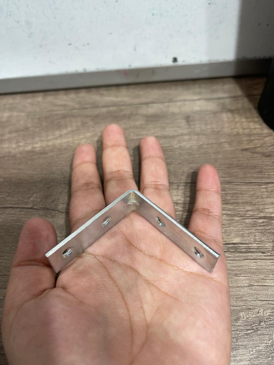
Several laser cuts with exactly the same shape were placed to make the structure thicker. As I mentioned earlier, because I didn't consider that the sewing machine had much force, the first design with 3mm MDF ended up warping. I thought this could be solved by placing metal angles on each of the inner corners of the design.
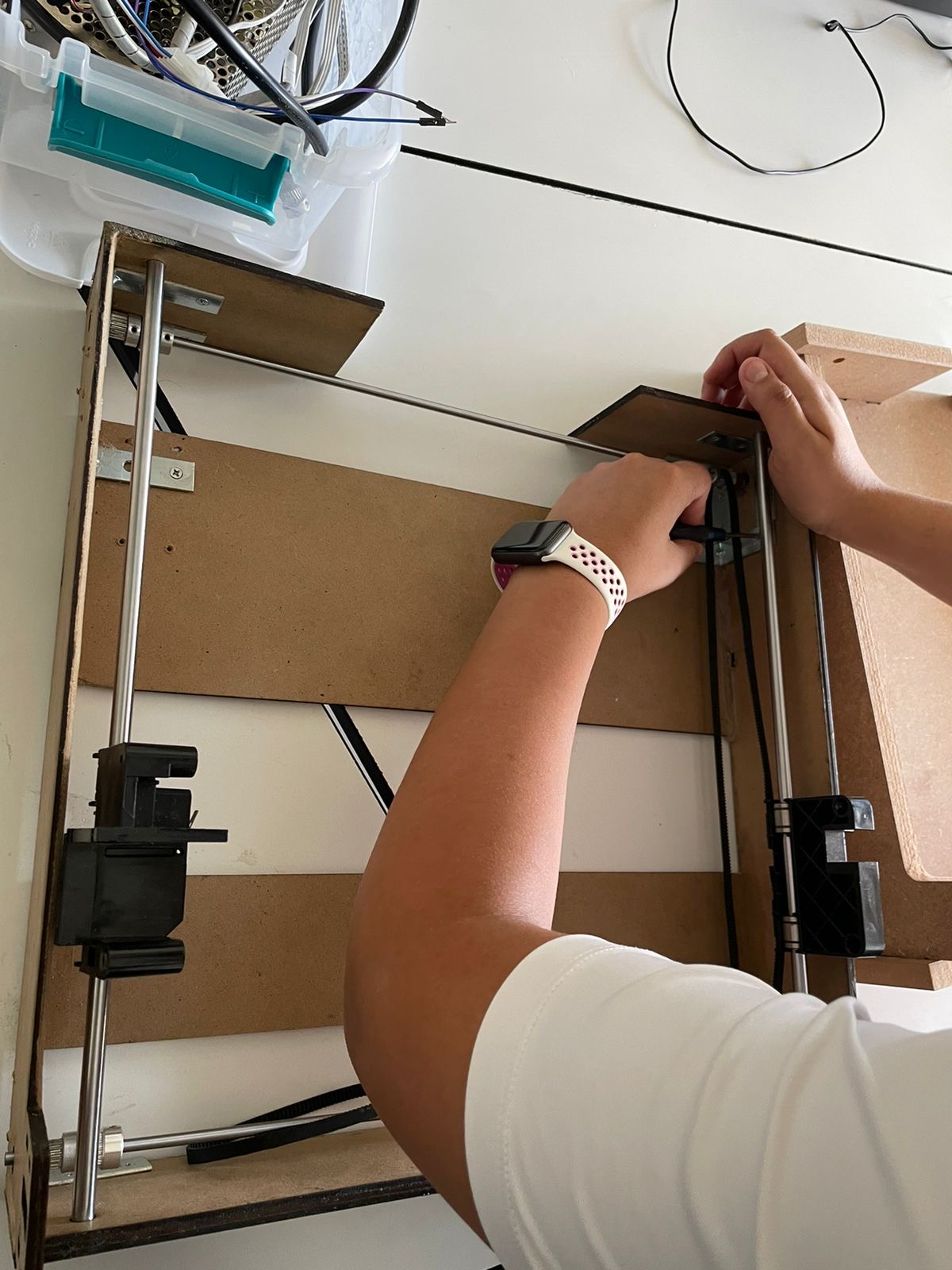
Another problem I encountered was that I thought I was miscalculating my measurements because on one side, the tube with its respective mechanism could fit and roll, but on the other side, it couldn't. However, in the end, I realized that one of the gears was at a different distance, so I had to adjust to avoid that.
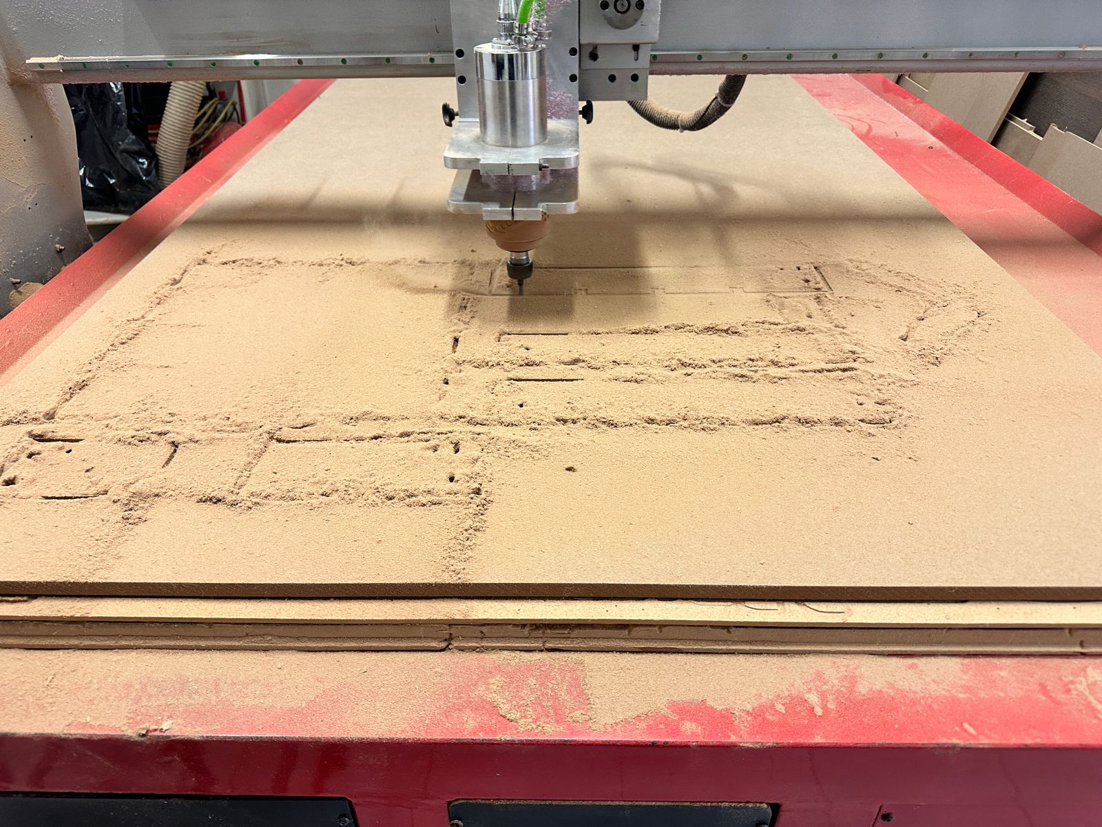
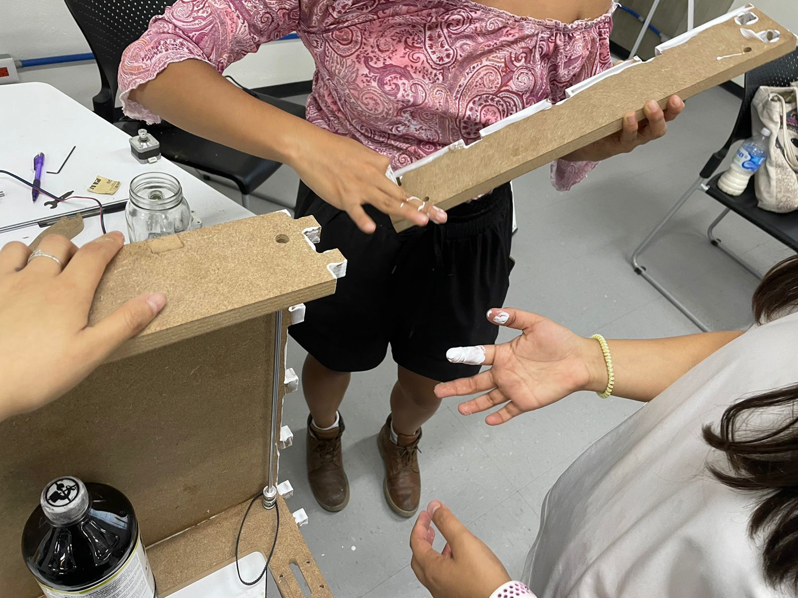
Due to its lack of aesthetics and still being prone to bending, it was decided that the design needed to be redone, maintaining the exact same measurements but with increased thickness. Thus, it was cut using a 15 mm MDF on the CNC router. However, one detail we noticed was that the cutting tool used was larger than expected, resulting in some material being removed and the pieces not fitting together perfectly. The solution was to apply adhesive to ensure a snug fit and prevent any wobbling. Another important aspect of this redesign was one of the sides supporting one of the motors, as the belt used to rotate the mechanism wasn't being tensioned enough. Therefore, I had to calculate how much larger that piece of the component should be.
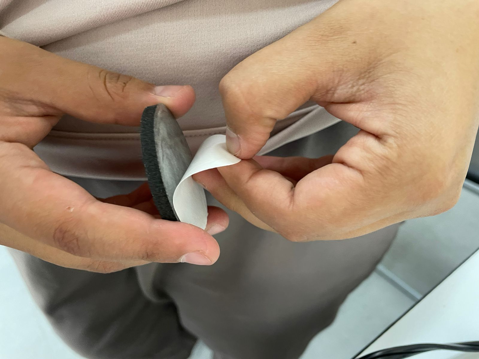
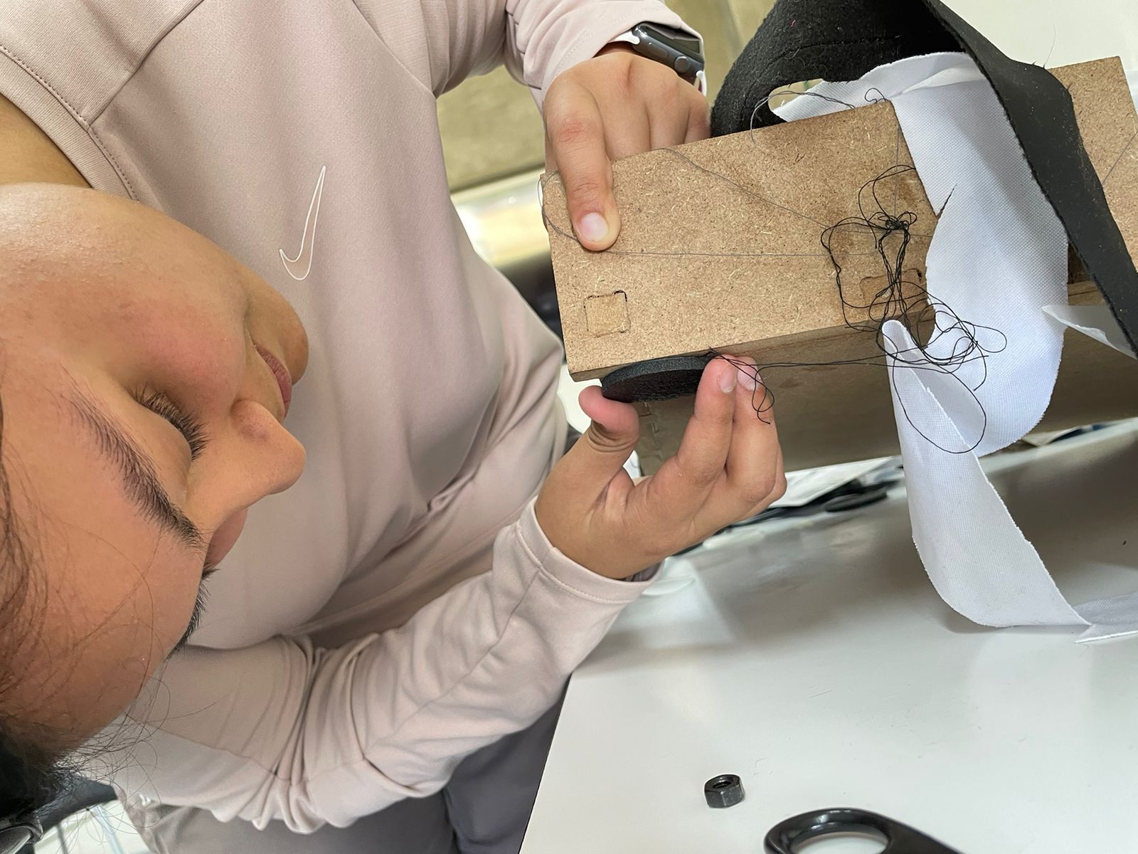
When we started conducting tests, we noticed that there was a vibration issue with the structure. To address this, we went and purchased some pads and placed them to prevent this vibration, thereby resolving the issue. However, later on, we realized that it was also a matter of programming, as too much power was being applied to the sewing machine's speed, causing excessive vibration. But after making these adjustments, the issue was resolved.
NOTE: It is important to mention that the download files for the final designs are located on our team's group page.