5. 3D printing & scanning
Group assignment:
Group Assignment for week 5, Fab Puebla.
We tested the design rules for our 3D printers, focusing on key aspects such as overhangs, printing angles, and bridging. Overhangs up to 45 degrees printed well without supports, while bridging tests demonstrated that shorter spans could be achieved without sagging, depending on material properties. We optimized wall thickness, finding that thin walls less than 1mm lacked strength, whereas very thick walls over 5mm wasted material and time. Regular calibration helped maintain dimensional accuracy, addressing issues of material shrinkage. Anisotropy testing ensured strength in the desired directions by aligning critical stress points with the printer’s strongest axis.
Additionally, we improved surface finish quality through higher resolution settings and post-processing techniques. Maintaining adequate clearance (0.2mm to 0.5mm) between support structures and the part ensured easy removal without damage. Infill density was adjusted based on the application’s needs, with prototypes using around 20% infill and functional parts requiring 50% or more for added strength. These adjustments have significantly enhanced the quality and reliability of our 3D printed models.
Design Considerations for 3D Printing
Initially, I investigated the factors to consider when designing parts for 3D printing. This was primarily compared to injection molding, which produces similar parts from identical materials but has significantly different design requirements.
1. I discovered that fillets are beneficial; the more fillets, the smoother the toolpaths, leading to parts that are cleaner and more dimensionally accurate. This improvement is primarily because the print head does not have to change directions as abruptly, thereby reducing vibration and maintaining a steadier speed.
2. It's important to consider the anisotropy inherent in 3D printing. For functional parts that must withstand weight or strain, remember that 3D printed parts are highly anisotropic – they tend to break along the same axis as the layer lines since the interlayer bonds are weak points. Therefore, you should apply force perpendicular to these lines. This necessitates considering the print orientation from the outset to ensure the part's strength aligns with the required axis.
3. In injection molding, the most effective way to reduce costs is by decreasing the volume of the part, thus using less plastic per piece. In contrast, the main cost driver in 3D printing is not the material but the print time, which is most significantly impacted by surface area. Thus, for 3D printed parts, reducing surface area is the most effective cost-cutting strategy. Note that adding ridges and insets increases surface area and print time without significantly saving material.
4. Overhangs are problematic in prints as they tend to sag or fail entirely. To enhance the reliability of your prints, add chamfers or bevels to support new layers. This approach not only makes prints look cleaner and prevents sagging but also strengthens them. This recommendation aligns with the first tip.
5. One of the most significant limitations of 3D printing compared to injection molding, which demands effective mold designs, demold angles, and uniformity, is non-existent in 3D printing. 3D printing allows for the production of parts that are already assembled, including objects within objects and interconnected parts that cannot be separated or do not require assembly.
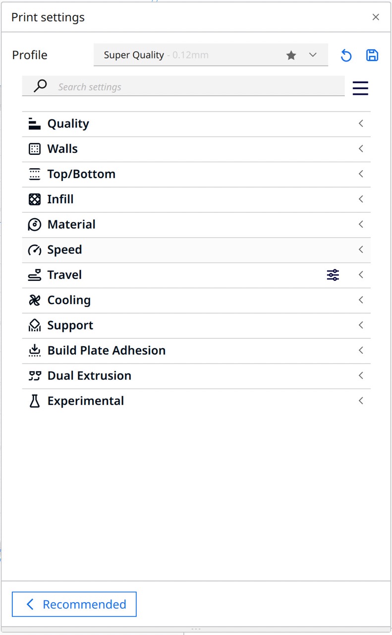
Slicing in Cura:
Once you have your model, you need to slice it into layers and convert it into G-code, which your printer will be able to read and execute.
There are many factors to consider, so I will provide a brief description of the most important ones and supply you with a link to view more in-depth videos on using more advanced features in CURA:
- Layer Height: This is pretty self-explanatory; it determines the height of each layer and therefore the total number of layers. The smaller the height, the finer the texture will be, but also the more passes and, therefore, the longer it will take to print.
- Line Width: This factor is very similar to the previous one in that the wider the width, the fewer lines you need to print and the faster the print will be. This is also dependent on the size of your nozzle; I tried 0.2, 0.4, and 0.8.
- Walls: This factor is important as it determines the strength of the outer layer of your part but can also significantly increase your print time.
- Top/Bottom: This determines the number of layers at the top and bottom of your piece. These are usually solid and act pretty much like walls.
- Material: Here, you inform the printer of the material you are using, which will determine the temperature at which you’ll want to extrude the filament, as well as the recommended bed temperature.
- Speed: This sets the speed at which you print. This is dependent on several factors; the common bottleneck is the extruder. In my case, the extruder is capable of heating filament very fast, so the bottleneck becomes the movement and rattling of the frame at very high speeds.
- Cooling (Min print time): This sets the speed of the fans. The higher the speed, the faster the extruded filament will cool, preventing it from drooping. One interesting thing I found in this section is the minimum layer time; it is set to 10 seconds by default, but reducing it to 1 second worked for me and made some of my prints much faster.
- Support: This feature allows you to print overhangs without trying to print mid-air. The defaults are like small columns underneath your print, but I prefer tree supports as they are usually faster and can be placed just on the print bed, avoiding the part and maintaining a cleaner surface finish.
- Build Plate Adhesion: This is very important if you don’t want to end up with a spaghetti mess, as I had a couple of those. There are different types of bed adhesion, but the idea is that they increase the surface area that directly touches the print surface, making it less likely that the printed part will dislodge itself mid-print, ruining the final product. I tend to use a brim, but for really unsteady prints, you can use a raft, which is like a brim but several layers instead of just one.
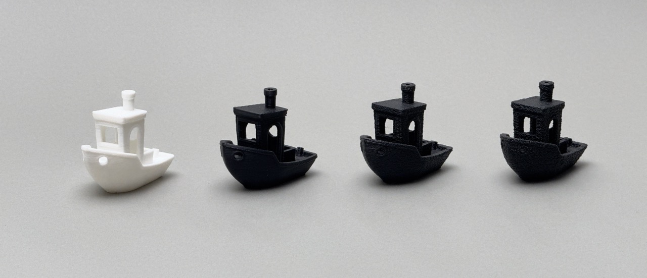
- Experimental: This is an interesting section I haven’t explored deeply but has some intriguing features. The main one I tried was fuzzy skin. I tried it on a benchy at different levels of intensity and managed to get an interesting rough surface. This also helps hide layer lines or at least makes it less obvious that the object is 3D printed.
Printing:
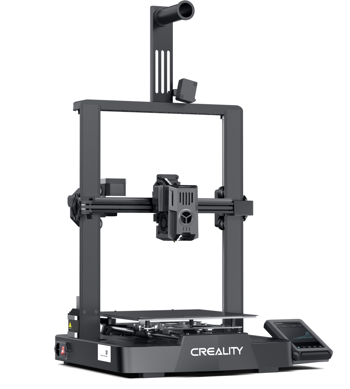
I got a printer for this week's assignment, an Ender V3 KE specifically. I initially bought an SE but after hours of fiddling with it and trying to get it to print, I found out the extruder motor was dead. So I decided to return it and upgrade to the KE which is essentially the same printer except it has a better hot end that can extrude faster and a filament runout detector.
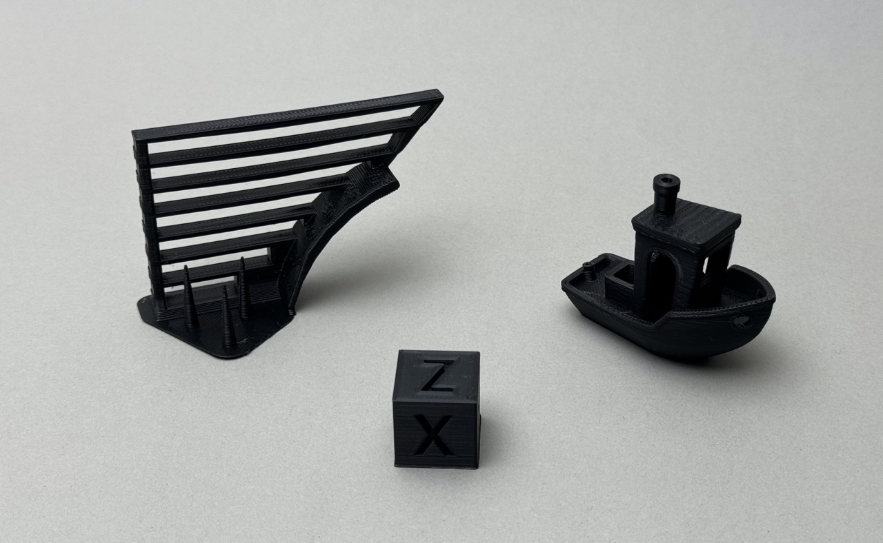
Since I was using a different printer as the rest of the class I decided to carry out a couple of tests to see if the machine was properly calibrated, stringing, overhangs, speed tests, and different filaments, all PLA but some were newer than others so I thought the varying levels of moisture could have an effect on the final result.
I found out the hard way that it is important to monitor your print, especially the beginning, making sure the base adheres properly to the print surface, I had a print fail practically at the start and ended up wasting tons of plastic and making a huge ball of spaghetti. From that point on I’ve always sat around waiting for the first few layers and checked periodically on it to stop it if it fails and restart the print. I found that making the first layers a little slower helped increase the success rate.
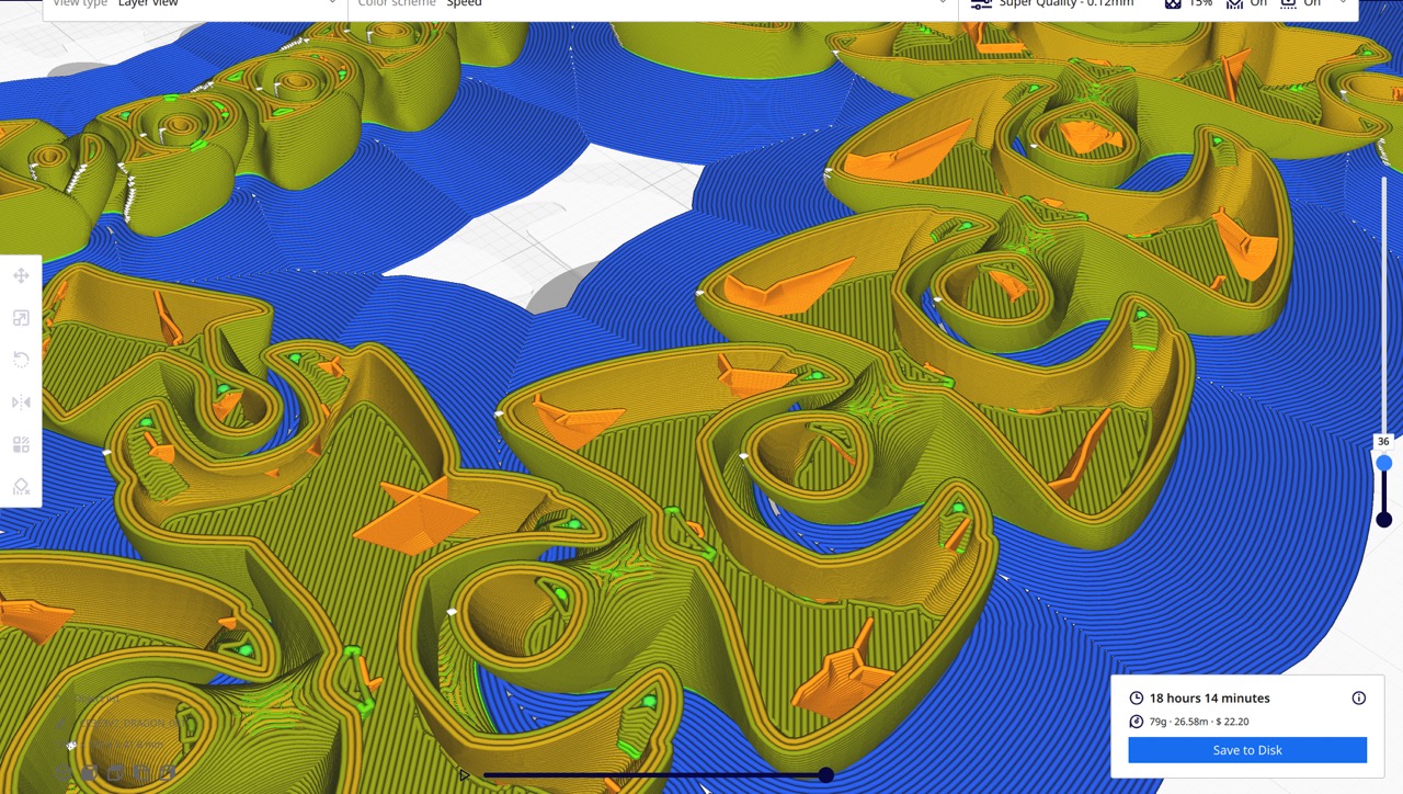
Many of my prints took some fiddling with the settings to get them just right, 2 in particular. First was a benchy, a speed benchy, the printer has a preloaded file that prints a bench in 16 minutes, which is impressive, but when I tried importing a benchy into CURA the time was more like one hour. This was very surprising so I started watching videos and reading posts on forums looking for the magic settings that would make my printer print that fast. Unfortunately, I never found that setting, and my attempts at printing a 23-minute benchy were pretty underwhelming, I had to increase the layer height and line width as far as it could go, increased the speed as far as I felt comfortable with, reduced the min print time… the piece drooped and looked horrible. Although this didn’t reach the desired outcome I learned what the limits of my machine were, I got comfortable with some of the terminology and found some great 3d printing YouTube channels, YouTube really is a great resource for learning.
But enough tests, now let’s focus on the projects for this week's assignment. For the modeling portion, I wanted to make a joint that could not be manufactured with injection molding or subtractive manufacturing. I started by looking for interesting joints and shapes on thingiverse.com, downloading them and then opening them in Cura. There I could check the geometry of those joints by moving the layer slider and seeing how they constructed print in place joints. I ended up deciding to try to design and print my own ball and socket joint. I wanted to be able to print it already attached with no need for assembly and I also wanted it to be impossible to pull it out accidentally.
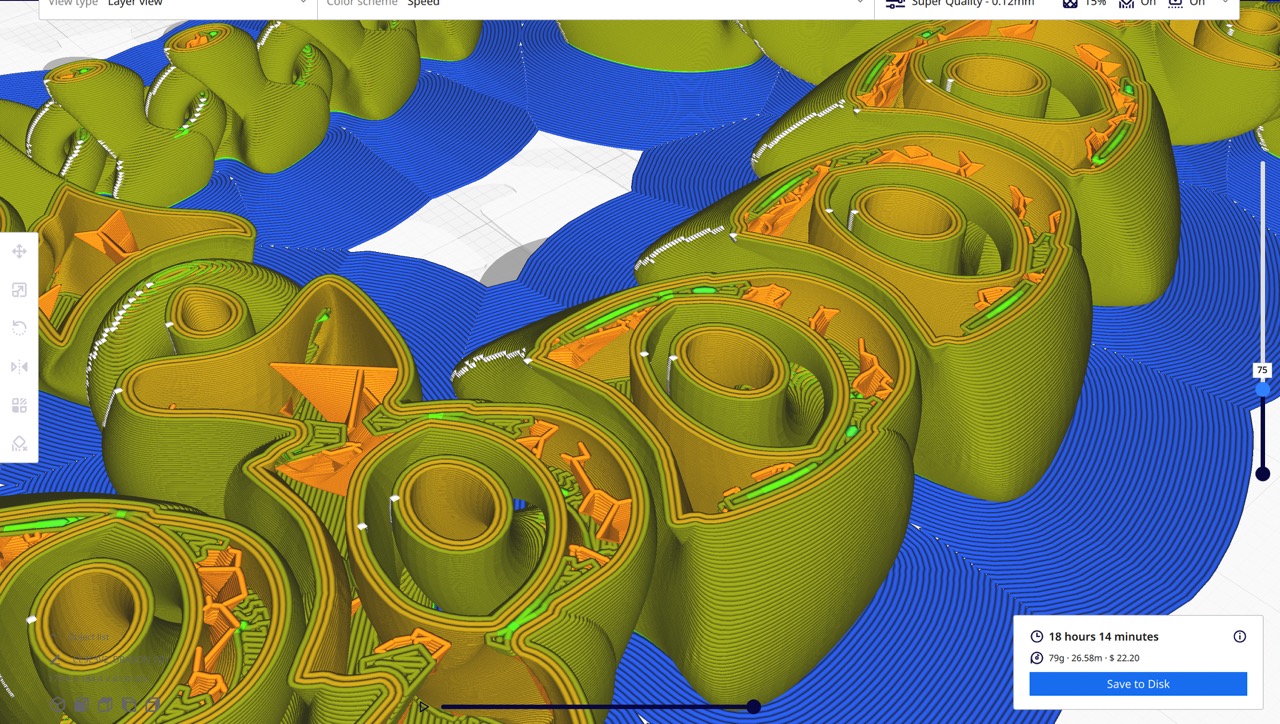
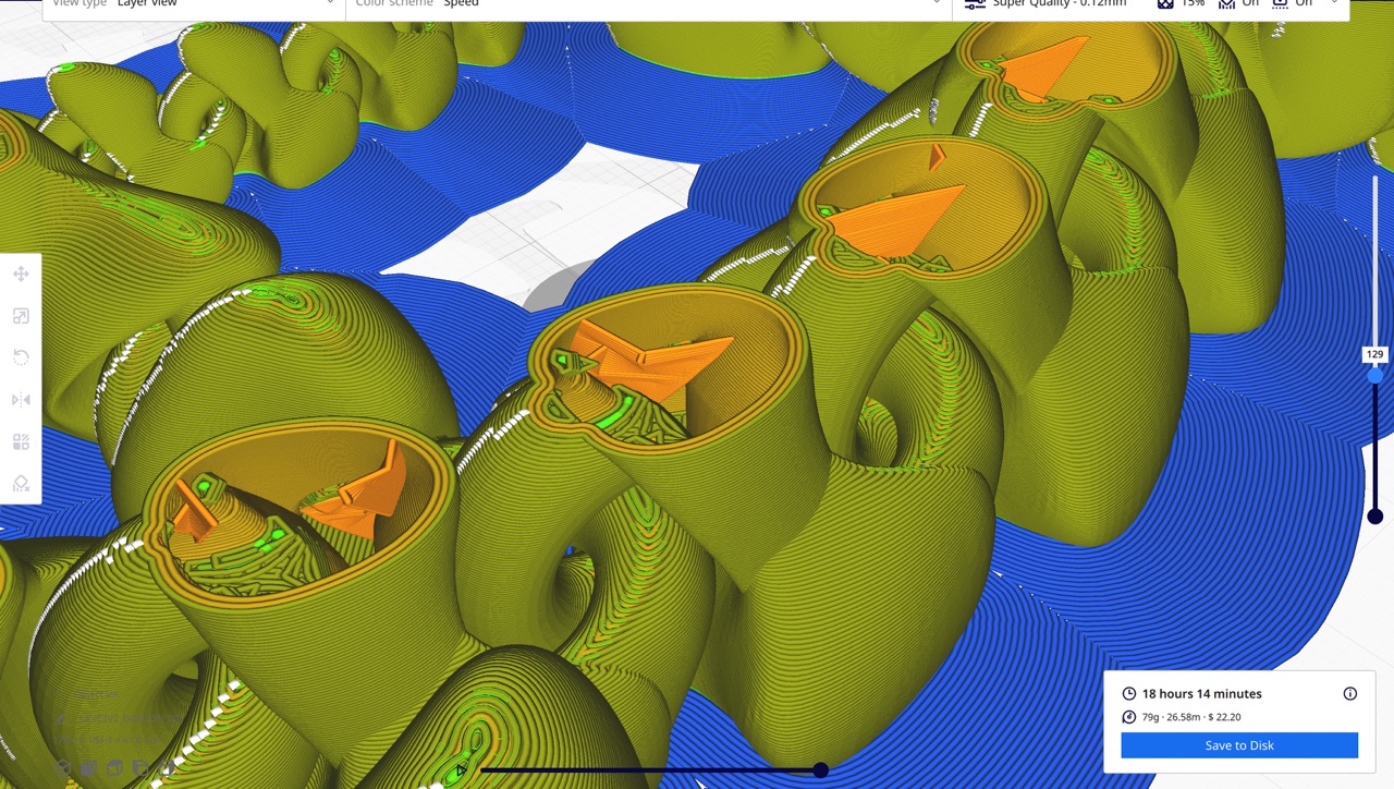
I started by looking for some tutorials and guides to get my settings in the ballpark. I knew there would be a lot of experimenting with the settings and so it was worth it to construct a parametric design that I could easily modify so I could apply my observations to the design.
 I started by printing a piece that had too small of a gap, so the two pieces fused together and I broke
it trying to separate the two pieces. I improved the second version by fixing the gap and I also made the
base a little shorter and thinner since I was just wasting material and print time. The second one printed
faster and had a larger gap, but not large enough, so I printed a third, but the gap was now too large and
the piece dislodged mid print, making that print unusable too. The fourth finally worked, and it worked
great, it took little force to separate the two pieces and now it works smoothly. Then I got ambitious and
tried to print two stacked on top of each other, unfortunately, I couldn’t find an appropriate gap that would
allow it to separate but not mid print, I ended up with lots of single joints with rough ends. I learned a
lot by printing several pieces with slightly different dimensions, in the future, I want to try more prints
when I have more time. I hadn’t anticipated all the time I would lose with failed prints and with the
inefficiency of printing at home but spending most of the day in school. Most of these prints took a couple
of hours and many of them failed. I believe I also have a problem with my filament
I started by printing a piece that had too small of a gap, so the two pieces fused together and I broke
it trying to separate the two pieces. I improved the second version by fixing the gap and I also made the
base a little shorter and thinner since I was just wasting material and print time. The second one printed
faster and had a larger gap, but not large enough, so I printed a third, but the gap was now too large and
the piece dislodged mid print, making that print unusable too. The fourth finally worked, and it worked
great, it took little force to separate the two pieces and now it works smoothly. Then I got ambitious and
tried to print two stacked on top of each other, unfortunately, I couldn’t find an appropriate gap that would
allow it to separate but not mid print, I ended up with lots of single joints with rough ends. I learned a
lot by printing several pieces with slightly different dimensions, in the future, I want to try more prints
when I have more time. I hadn’t anticipated all the time I would lose with failed prints and with the
inefficiency of printing at home but spending most of the day in school. Most of these prints took a couple
of hours and many of them failed. I believe I also have a problem with my filament
3D Scanning:
 I experimented with several apps for photo scanning and found significant differences among LiDAR, photogrammetry, and
NERFs/Gaussian splatting. I found NERFs and Gaussian splatting fascinating and look forward to their development over time.
Unfortunately, they generate point clouds, which can't directly be used for 3D printing since that requires a mesh.
Therefore, I only tested them without considering them for 3D printing. I then tried both LiDAR and photogrammetry. I believe
LiDAR is more precise; however, it has a limitation: it offers lower resolution than photogrammetry for close-up objects.
Thus, it is well-suited for scanning large objects like rooms and cars but not ideal for smaller, more detailed objects.
I observed the infrared pattern of LiDAR on the iPhone and noted that the dots are quite large and sparse, so I decided to
opt for photogrammetry. I aimed to use only free software and was interested in trying AliceVision.org since it's open-source
and comprehensive, but it only runs on Windows, which was a limitation for me. Consequently, I ended up using my iPhone and
an app called KIRI Engine. It's not entirely free but offers a trial period, and I managed to complete a few scans.
I experimented with several apps for photo scanning and found significant differences among LiDAR, photogrammetry, and
NERFs/Gaussian splatting. I found NERFs and Gaussian splatting fascinating and look forward to their development over time.
Unfortunately, they generate point clouds, which can't directly be used for 3D printing since that requires a mesh.
Therefore, I only tested them without considering them for 3D printing. I then tried both LiDAR and photogrammetry. I believe
LiDAR is more precise; however, it has a limitation: it offers lower resolution than photogrammetry for close-up objects.
Thus, it is well-suited for scanning large objects like rooms and cars but not ideal for smaller, more detailed objects.
I observed the infrared pattern of LiDAR on the iPhone and noted that the dots are quite large and sparse, so I decided to
opt for photogrammetry. I aimed to use only free software and was interested in trying AliceVision.org since it's open-source
and comprehensive, but it only runs on Windows, which was a limitation for me. Consequently, I ended up using my iPhone and
an app called KIRI Engine. It's not entirely free but offers a trial period, and I managed to complete a few scans.
The process of photo scanning was relatively straightforward. However, since the models are processed in the cloud and I was using the free version, obtaining the results took some time. I began by scanning a plant pot outdoors; unfortunately, it scanned the entire garden as well as the plant, resulting in relatively poor resolution for the plant's mesh and a subpar outcome. The next attempt was indoors, using two photography lights aimed at the ceiling to provide very even and soft lighting, which led to a much better result.
After conducting numerous tests, I have a few tips:
- Scan objects that are neither transparent nor shiny, as these qualities can confuse the software.
- Utilize soft, even lighting to prevent embedding shadows and reflections into the texture.
- Ensure all the photos overlap significantly.
- Remain stationary when capturing each photograph and use a high shutter speed to avoid motion blur.
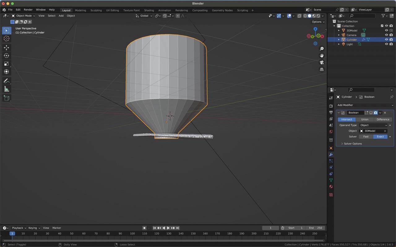
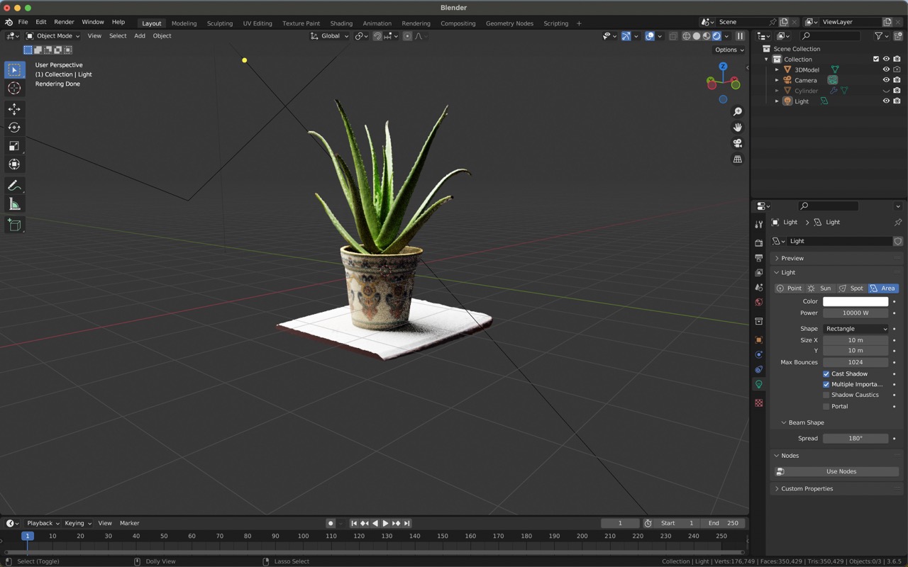
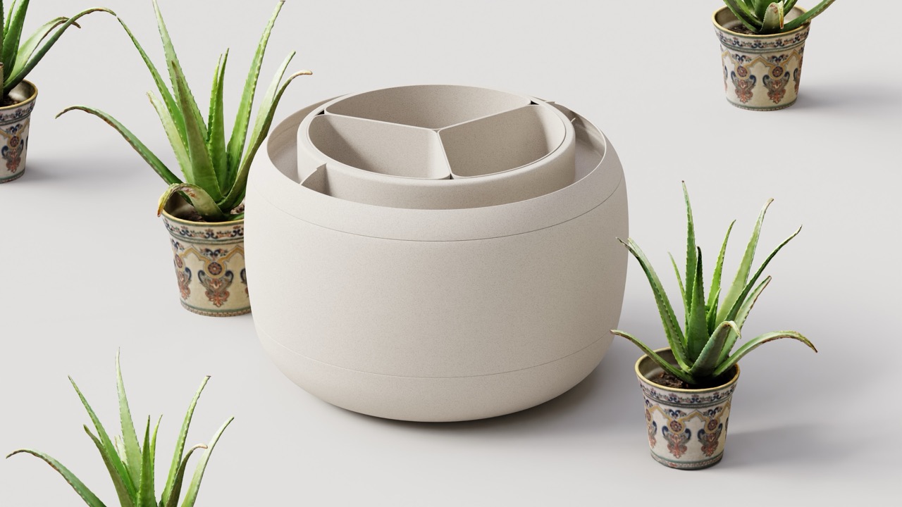
After the scan was completed and processed, I exported it as an OBJ file and opened it in Blender. There, I eliminated the unwanted parts of the scan and the ground using a boolean modifier. This procedure resulted in a model consisting of a plant pot and an agave plant. I decided to illuminate the scene with an HDRI and render a frame. The render turned out well, but I wished for a higher texture resolution, as the current one diminishes the realism and appears slightly out of focus.
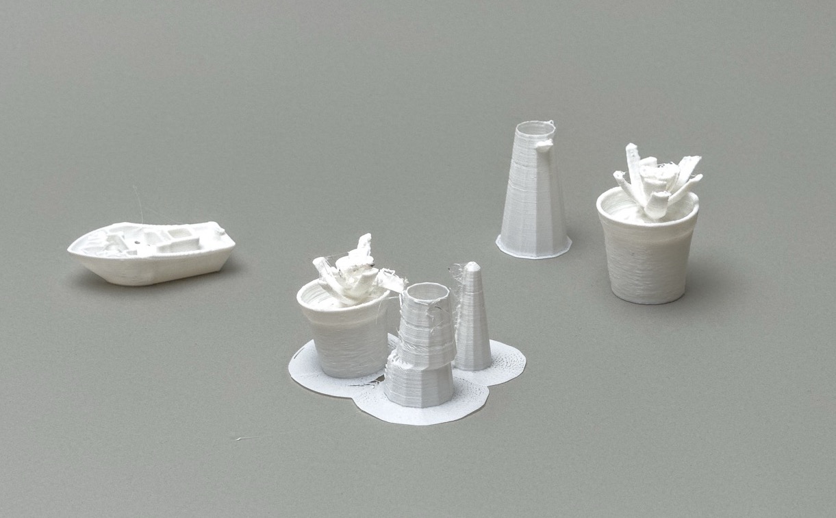
Subsequently, I attempted to 3D print the plant but encountered failures at the same stage twice; the exact cause remains unclear. For the second attempt, I made the model slightly smaller to expedite the printing process, as I had numerous tests to conduct. Regrettably, it still failed. In my next attempt, I will incorporate a raft to ensure the model does not detach midway through the printing process.
Modelling Piece
For the modelling part I decided to try to print a socket joint in one go. This required extensive iteration and investigation since it was hard to pinpoint the exact measurements which would lead to the two parts not fusing into one but also keeping the ball rotating freely while simultaneously keeping the ball from popping out of the socket. To do this I decided making a parametric design would be ideal since it allows for fast design itteration, changing the size of gaps several time and printing many simutaneously during the night.
I used many parameters, here is a list of all the parameters I used:
| Name | Unit | Expression | Value |
|---|---|---|---|
| Ball_Diameter | mm | 15 mm | 15.00 |
| Neck_length | mm | 14 mm | 14.00 |
| Neck_radius | mm | 4 mm | 4.00 |
| Neck_bevel_radius | mm | 1 mm | 1.00 |
| Gap_ball | mm | 0.5 mm | 0.50 |
| Gap_pieces | mm | 0.25 mm | 0.25 |
| Socket_length | mm | 15 mm | 15.00 |
| Socket_width | mm | 22 mm | 22.00 |
| Socket_inner_dia. | mm | Ball_Diameter + (2 * Gap_ball) | 16.00 |
| Offset_centers | mm | Gap_ball - Gap_pieces | 0.25 |
| Ball_inset_depth | mm | 4 mm | 4.00 |
| Rotation_angle | deg | 120 deg | 120.0 |
The biggest takeaway from this exercise was to take the time to draw out and design the shape and most measurements beforehand, this will allow you to construct the shape in the correct order and using the most relevant parameters for your specific needs. You can design compound parameters which can sometimes be the most usefull since you might not want to change ever single little detail just an overall idea. This is something I didn't do during this design process, I a shotgun method, making parameters for absolutely everything I thought I could possibly need to change.
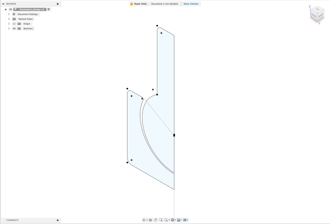
The main parameters I modified for the iteration process were the size of the gap between the walls and the ball and the height of the ball. The main idea was to have the ball be "floating" in the 3d model leading to the actual 3d print be connected only by one single point at the bottom of the sphere while also allowing for enough space for the ball to move feely in the socket without the gap being large enough to let the ball leave the socket.
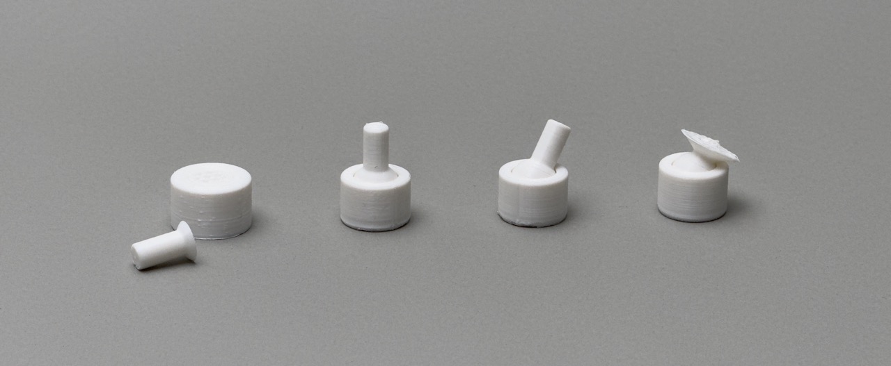
Here are some of the most notable fails and the one perfect piece. The first as you can see fused into a single piece, in fact they fused so strongly that I broke the rod trying to make it move. The second was better and had clear spaces between the ball and the socket but still didn't move, the third moved easily, but took a lot of effort to break loose and the one furthest to the right is the one that came out perfect. You might notice that in this lineup they were all hard to break apart and none were too easy to separate, this is because the ones that were too easy to break appart were actually so easy to break appart that they usually separated while printing and so never finished printing.
Videos
- Ironing
- Piece tolerances
- Tolerances
- Ball socket joint distance between pieces
- 3D Design considerations
- Improving curved surfaces