3. Computer Controlled Cutting
This week I learnt how to operate both laser cutters and vinil cutters as well as how to design with it's oportunities and around it's limitations
Group assignment:
As a group we conducted a systematic characterization of the CAM-five brand laser cutters at FabLab Puebla to optimize their performance and ensure uniformity across different machines. Initially, we cataloged each machine’s capability to handle a diverse range of materials—from soft fabrics to hard substances like MDF and acrylic. Subsequently, we subjected the machines to a series of tests to identify the optimal operational parameters such as power, speed, and frequency, determining the best settings for various materials.
Group Assignment for week 3, Fab Puebla.
In our characterization tests of the laser cutting machines, we observed that power settings below 30% were generally inadequate for cutting, with 10% power insufficient even for engraving. We found that optimal cutting performance was achieved at 50% power paired with a speed of 40 mm/s, where the cuts were clean and efficient. Conversely, slower speeds led to significant burning, highlighting a degradation in cut quality. These findings suggest that for clean cuts, a balance of moderate speed and power is essential, avoiding extremes that either burn the material or fail to cut through completely. Additionally, at higher speeds, a proportionately higher power setting is necessary to maintain effective cutting, reinforcing a linear relationship between speed and power needs.
Laser Cutters:
I will primarily focus on describing my experience operating the machine, calculating kerf, validating and iterating.
Design & Ideation:
I started by drawing a preliminary design on Procreate, the point of this is to make my design more concrete and forces me to think about how the pieces will fit with each other and think of the parameters that I will use to make my parametric design. In this case I designed a grid and modules that can fit in it in different orientations.
Parametric design:
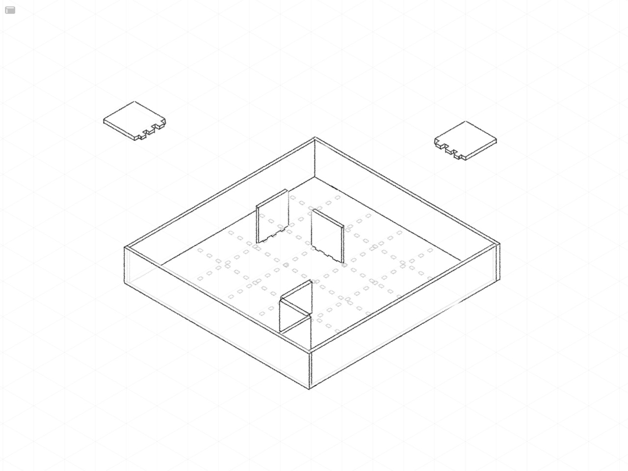
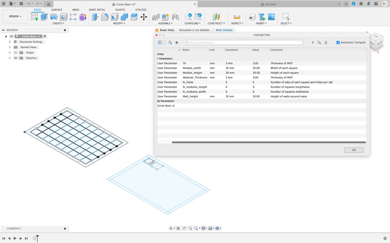
In developing the maze, I incorporated several adjustable parameters to ensure flexibility in the design process, using Fusion 360—a software known for its capability in creating parametric designs. These parameters allow for post-modeling adjustments to the maze’s dimensions and features based on specific needs. For instance, I included a parameter to alter the width of the gaps within the maze, accommodating adjustments for the size that best suits the hamsters, whether the existing gaps are too narrow or too wide.
Additionally, I set parameters to modify the overall height of the maze, as well as the number of squares it contains, and the number of pins present in each square. These adjustments can be made easily after the initial modeling, offering significant control over the final product’s functionality and appearance. Moreover, some parameters are designed to be interdependent, calculated by multiplying two existing parameters, thereby enhancing the design’s adaptability and complexity.
This design approach offers numerous advantages that are instrumental in both the development and refinement of a product. Firstly, it facilitates early-stage modeling, enabling us to begin our work even without final measurements. This significantly enhances workflow efficiency by allowing the design process to start without delays. Additionally, the flexibility to experiment with various measurements easily is a critical feature. This flexibility supports iterative design, a process essential for refining and perfecting a product through repeated modifications and improvements.
It also allows for swift adaptations of the design to meet future applications, enhancing the design’s versatility and long-term value. Furthermore, sharing these adaptable designs with others is straightforward. It provides collaborators or subsequent users with a solid foundation, yet grants them the autonomy to tailor the design to meet their specific requirements. This not only broadens the utility of the design but also fosters collaboration and innovation among users.
Operation:
The operation of the machine, which was a Co2 laser cutter, was actually quite straightforward, slightly outdated perhaps, but simple nonetheless.
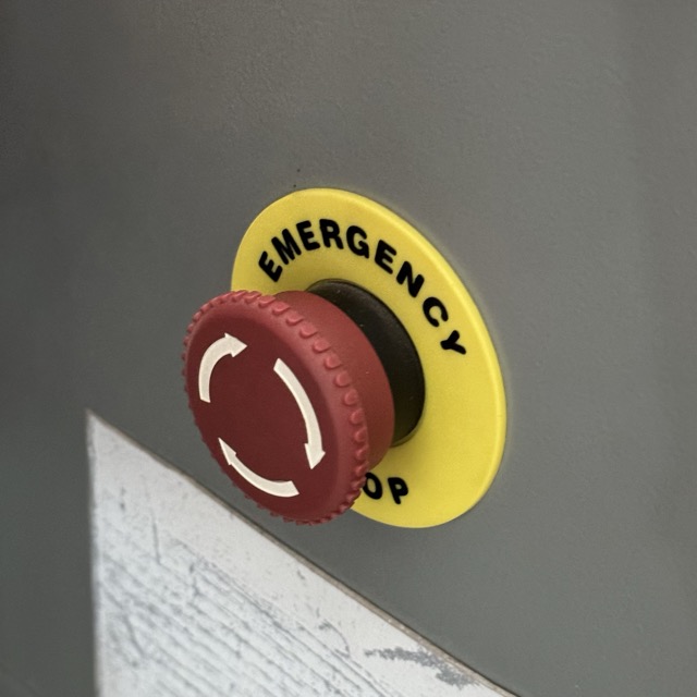
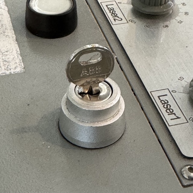
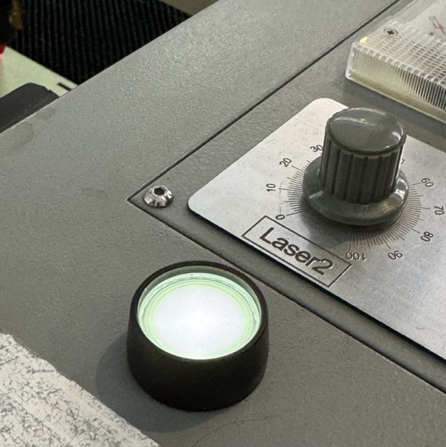
First, you need to turn on and unlock the machine. Power is supplied through an extension cord, which powers both the laser cutter and the ventilation system that automatically activates. Then, a physical key is required to unlock the machine, and the emergency brake must be disengaged.
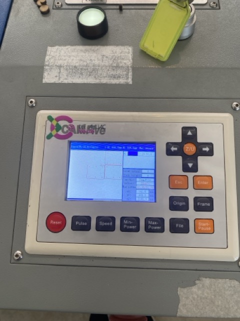
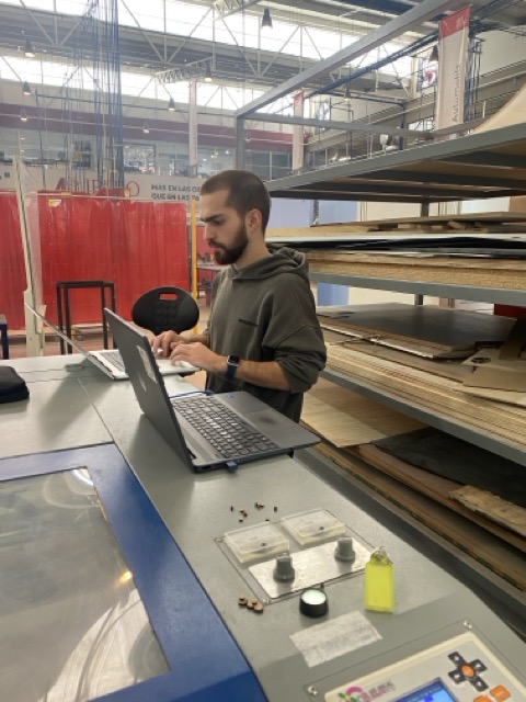
Once this is done, you can connect your laptop to the machine and use SmartCarve to prepare and execute the cut. The software boasts many useful features like "Go Scale," which displays the perimeter of the area it will be cutting, allowing you to ensure everything fits. It also includes functions for sizing, moving, and rotating objects, as well as controlling the laser's power and speed (details on these will be provided soon).
The reason I mentioned the software might be considered outdated is due to its appearance and functionality. First, it appears outdated, having not been fully redesigned in at least 15 years. I could overlook this if it were the only issue. However, my primary concern is that the software cannot operate without a key (in the form of a physical USB drive), and the machine cannot be manually operated without a laptop. Furthermore, it's no surprise that the software is incompatible with Macs, so I couldn't download it on my personal laptop. The ability to use the software independently, coupled with a virtual environment for simulating cuts, would have been extremely beneficial, saving a significant amount of time and material.
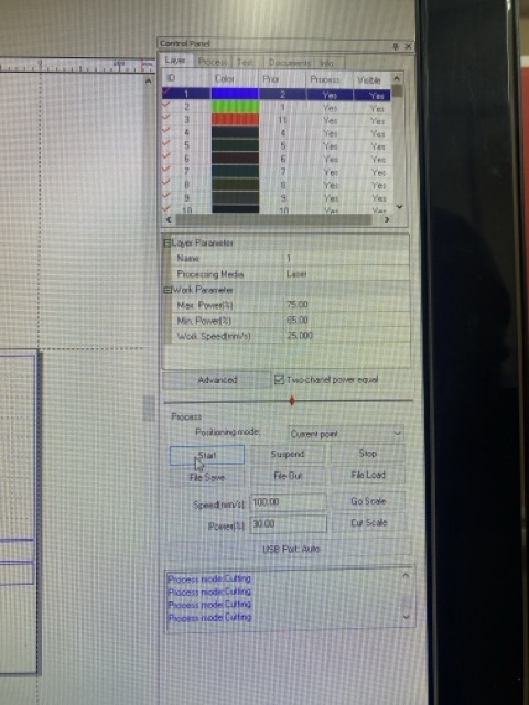
Based on the numbers we got from the group characterization I put everything in one layer since I wanted to cut everything and I didn't need to engrave anything so I set the laser to a max power of 75% and a speed of 25mm/s. If I had had to engrave anything I would add the design I wanted to engrave to another layer and set a different power and speed for it.
Kerf:
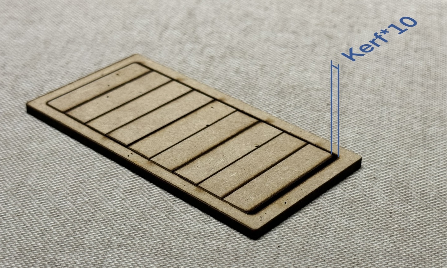
Kerf is the gap left behind after a cut, similar to the material removed when using a mill in a CNC router. The distinctive feature is the hourglass shape formed by two conical shapes, a result of the laser's focusing. This measurement is crucial as it affects the actual size of the shapes you cut, especially in pieces requiring tight tolerances, such as press fit.
I cut out a rectangle with 9 small rectangles inside. The point of this was to create a rectangular outer contour with 9 smaller rectangles that fit inside. If Kerf were 0 these ppieces would fit perfectly with no gap, but since Kerf is a factor we will have a gap, and since I chose to make 9 rectangles that's 10 vertical lines so whatever gap is left behind is Kerf*10. I chose to use 10 lines since it makes the division simple and exact and the more lines the lower the probability of a measurement error since the inacuracies of my measuring tool will be smaller in proportion to the measured distance. In this case my kerf was 0.18mm
Iteration and validation:
Once a cut is completed, you can evaluate how well it serves its function. If it is imperfect, it can always be redone. Through the process of iteration, we can achieve a more refined and robust product. In this specific instance, the fit of the pieces and the calculation of the Kerf were the main challenges I addressed through iteration.
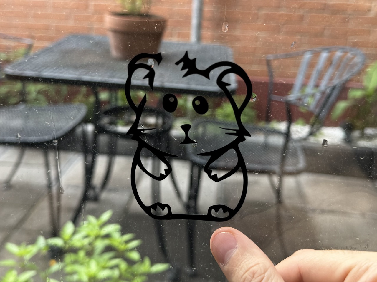
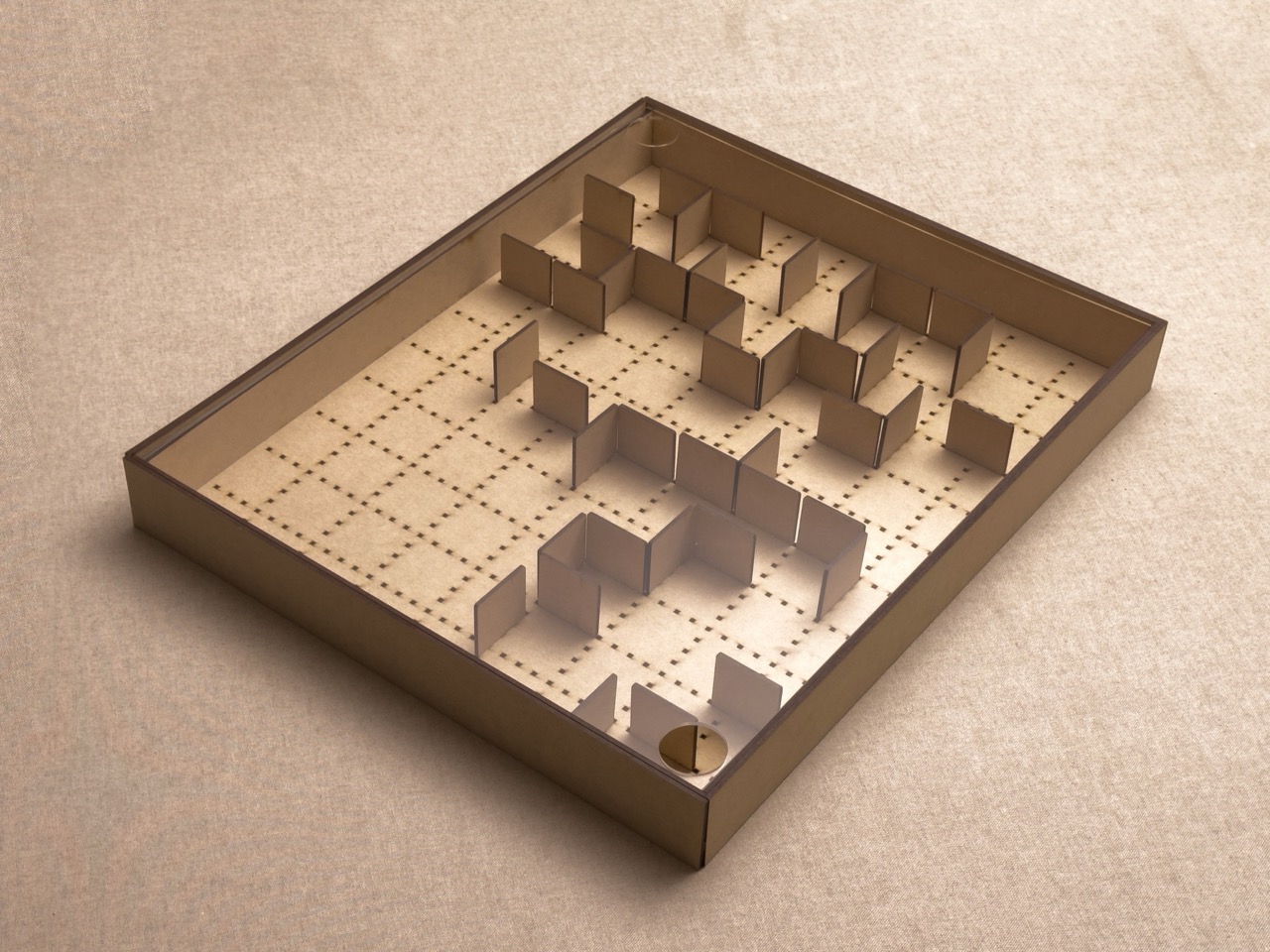
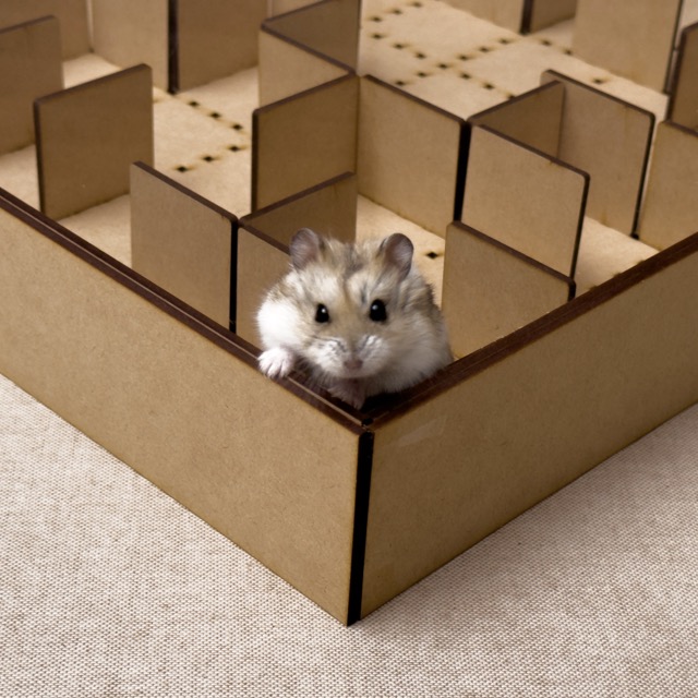
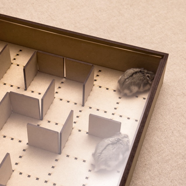
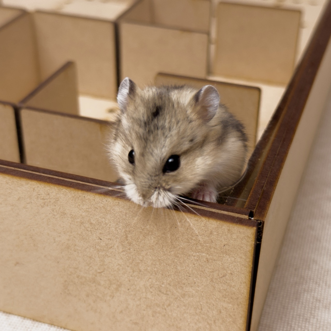
This is a Hamster Maze! Pretty self explanatory haha, I made it out of MDF (medium density fiberboard) and a scrap piece of acrylic I had laying around. The walls are removable and can be assembled into whatever path you like. The acrylic lid which rests on two bands of MDF has two holes, one to put the hamster in and the other for it to come out through.
Vinyl Cutter:
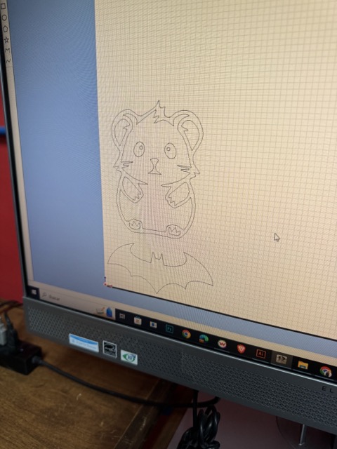
For the vinyl cutter portion of the assignment I decided to cut out the sillhouette of a hamster so I could stick it to the bottom of my laser cutting assignment which is a hamster maze.
Choosing an image and processing
When you want to cut something in vinyl, you need to consider two main factors. First, your image or logo must be limited to only two colors, which will translate into either vinyl or empty space. Additionally, any floating pieces will need to be peeled individually. Therefore, creating a pattern with numerous tiny unconnected dots, for example, will require a tedious and lengthy process of peeling. This is especially challenging if you aim to keep the vinyl dots and remove the surrounding vinyl, as it’s easy to accidentally peel off some of the small dots along with the surrounding vinyl.
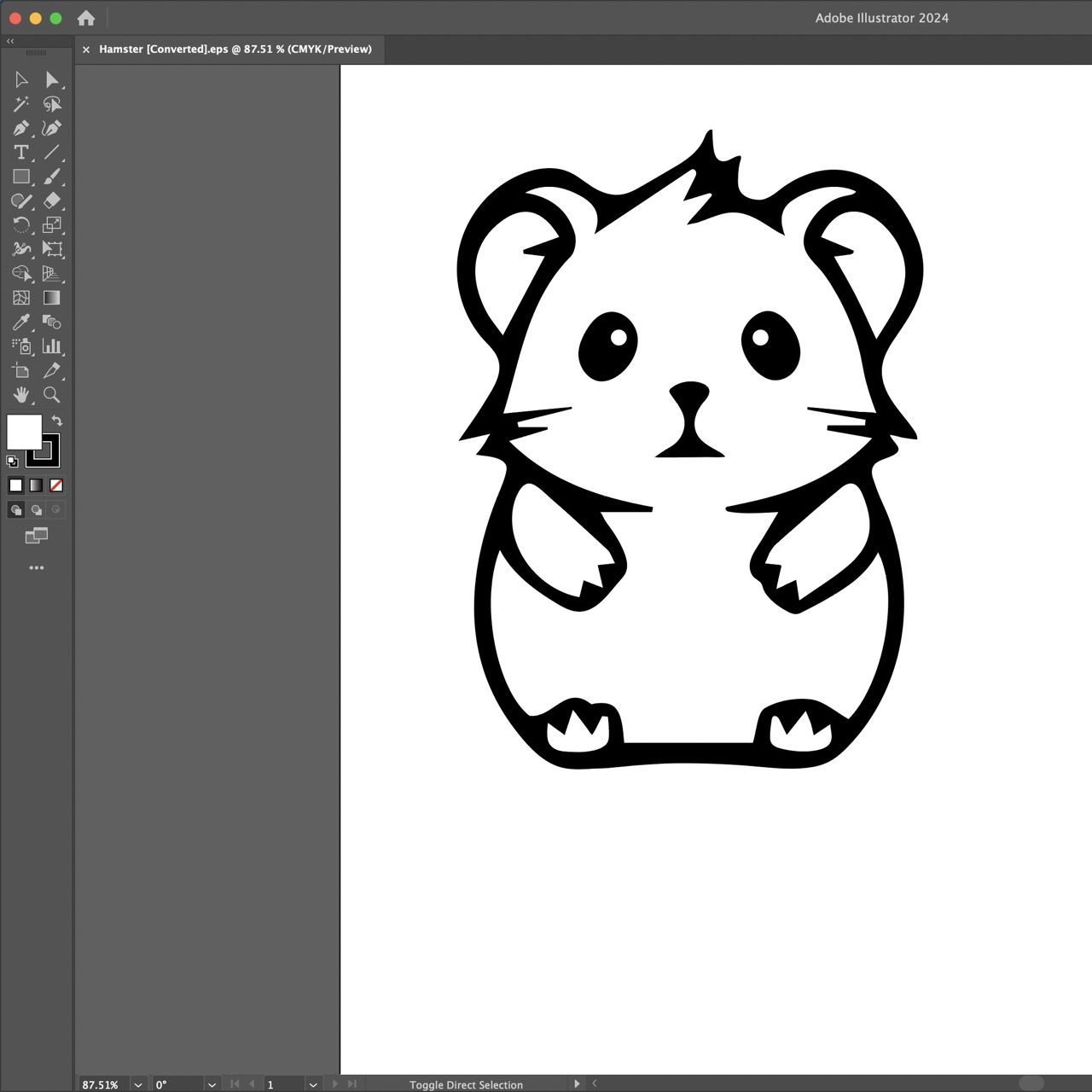

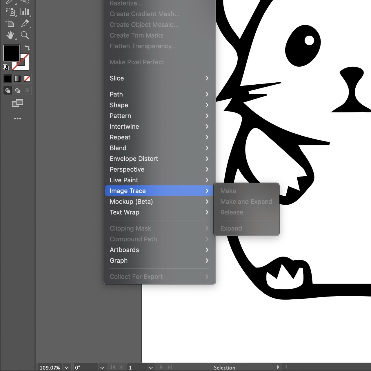
Another important consideration is that the file must be a vector drawing, as the instructions for the vinyl cutter’s movements are derived from these vectorial instructions. In my case, I chose an image that was initially a raster image and had to convert it to vector. This process isn’t always straightforward; factors such as resolution, complexity, and contrast of the image determine whether it can be done automatically or manually. I selected a high-resolution, black and white, and relatively simple image, which allowed me to use the “image trace” feature in Illustrator. While the conversion was mostly automatic, I had to retouch some fine details to ensure they looked good and were easy to cut. Another consideration when choosing your image is the size of the fine details, not relative to the rest of the image but in absolute terms, which requires knowing the size of your final cutout.
Export as a .eps file
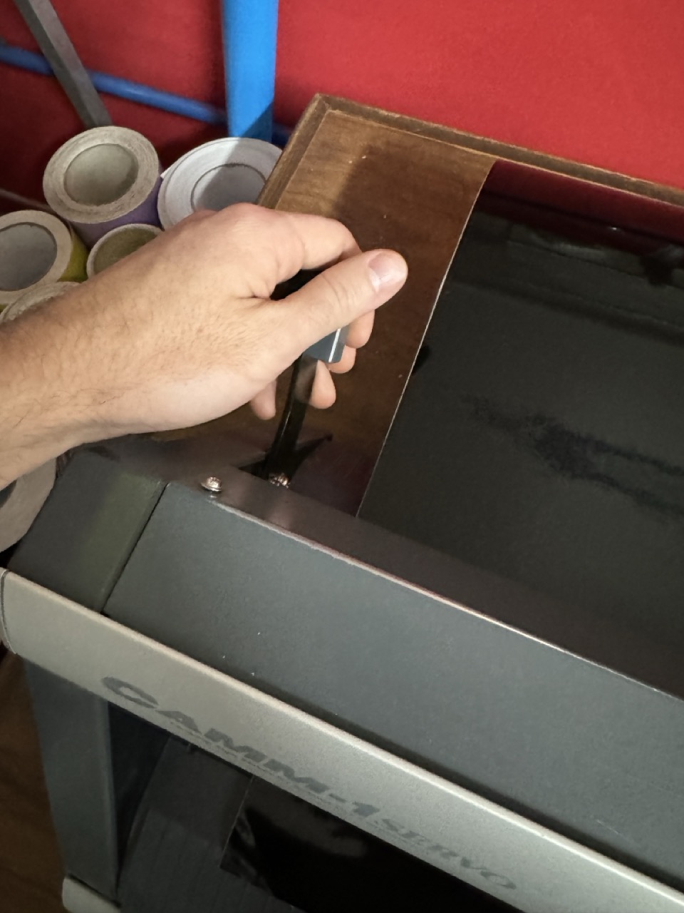
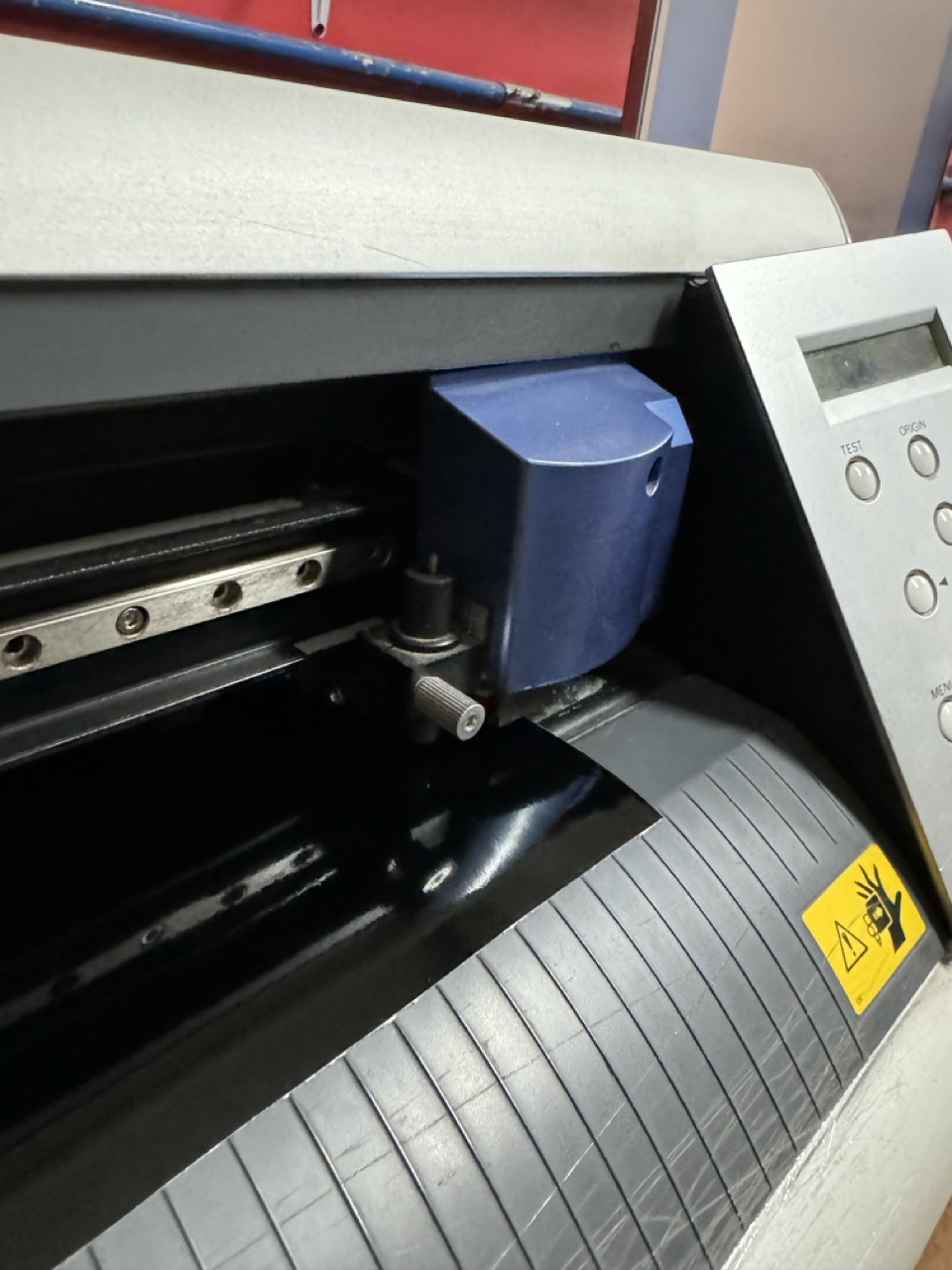
Operating the vilyl cutter
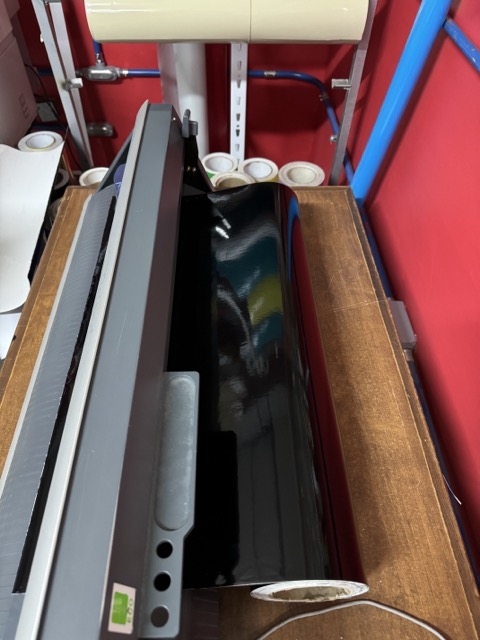
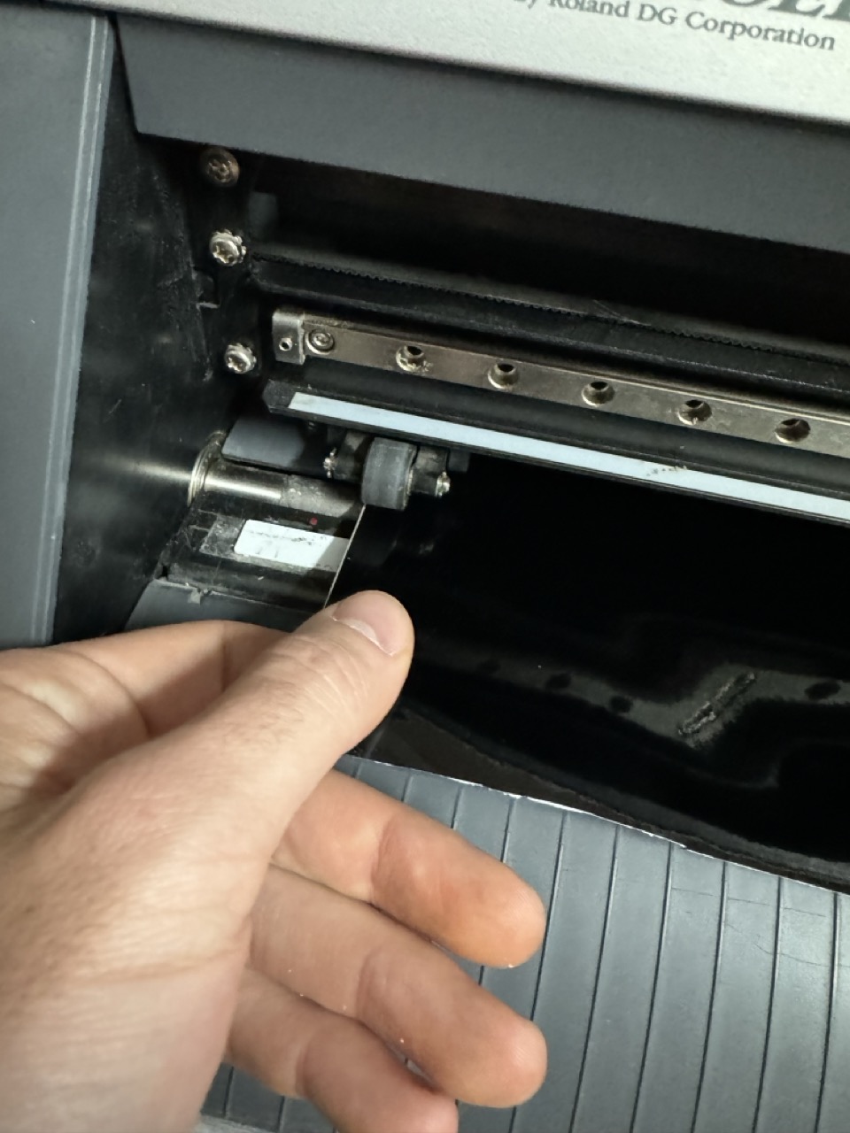
Setting up the vinyl cutter for my project was surprisingly straightforward. Initially, I inserted the vinyl into the machine, ensuring it was pushed all the way to the left until it reached the small guide wheel. This alignment is crucial as it helps maintain the vinyl’s straight feed into the cutter, crucial for precise cuts.
Once the vinyl was in place, I used the top lever to secure it firmly. This step is vital as it prevents any movement of the vinyl during the cutting process, which could lead to inaccuracies.
After securing the vinyl, I carefully moved the cutter head across the vinyl’s width. This check was to ensure that the vinyl lay smooth and flat without any creases underneath, which might affect the cutting quality. This straightforward setup process allowed me to efficiently prepare the vinyl cutter for the designs, ensuring that each cut was precise and clean, matching my project’s specifications.
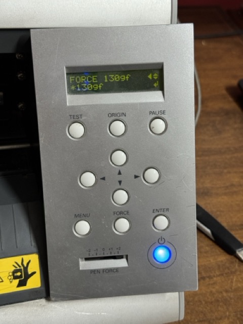
Once the vinil was secure I set the force to 130gf which is what this vinil was rated for to ensure it cut through the vinyl but not the layer of paper it's stuck to. Then I simply inserted the .eps file into the vinyl cutter's proprietary software and positioned my image in the right place and hit the cut button on the machine.
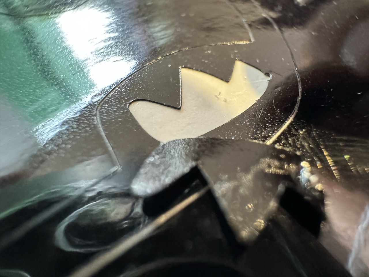
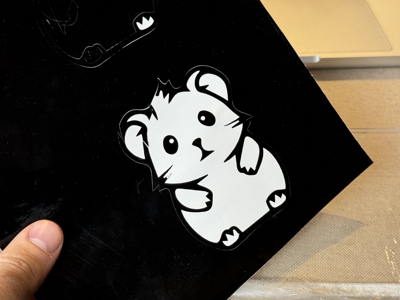
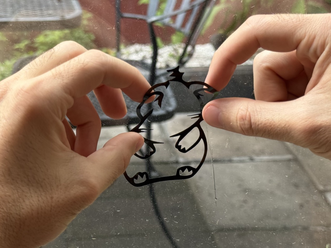
The final result came out great, once the cut was completed I peeled the rest of the vinil and transfered it to my final surface.