Computer-Controlled Machining
For this seventh week of the Fab Academy we will see the theme of Computer-Controlled Machining, which will have two assignments, the group and the individual, the group is the following: Complete your lab’s safety training, test runout, alignment, fixturing, speeds, feeds, materials and toolpaths for your machine document your work to the group work page and reflect on your individual page what you learned and
And the individual assignment is make (design+mill+assemble) something big.
Group assignment week 7
What is Computer-Controlled Machining?
Computer-controlled machining, also known as computer numerical control (CNC), is the automation of tools using a computer program. It is used to operate tools such as drills, lathes, mills, grinders, routers and 3D printers.
Instructions are delivered to a CNC machine in the form of a sequential program of machine control instructions, such as G code and M code, and then executed. The program can be written by a person or, much more often, generated by computer-aided design (CAD) software or computer-aided manufacturing (CAM) software.
Here are some dress rules that have to be followed in order to operate a CNC machine:
- Impact-proof safety goggles, as the chips can be projected because of the operations
- Noise protection headset, as the noise can get up to 70dBA near the machine
- 100% cotton Lab coat/overalls
- No hanging accessories like jewelry or garments
- NO Shorts
- Safety boots/shoes that have toe protection from falling heavy parts
- Breathing mask, as the operations can project fine dust depending on the material being processed
In addition to the appropriate clothing, you have to follow other rules while the CNC machine is working, these are some of them:
- The machine must be operated exclusively by trained staff
- Do not put your hands near the cutting area while the machine is working
- Do not wear gloves during the operation of the machine
This is me wearing the security equipment correctly.
.jpg)
This week is an important topic for my final project, the smart dog house so I decided to make a design to be able to go forward and not delay in my project.
Modeling
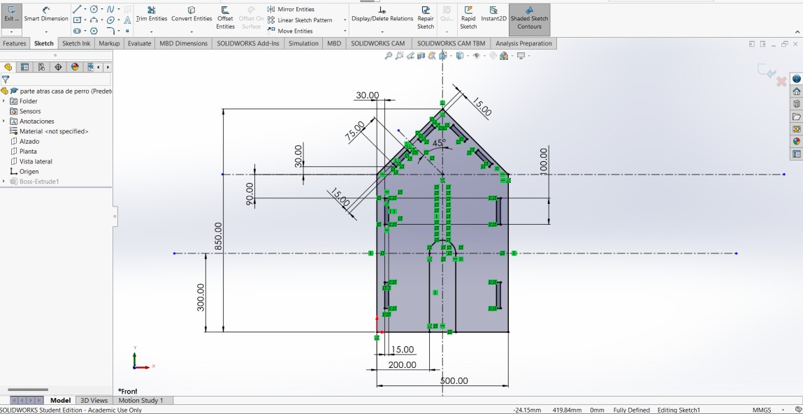
The modeling for the piece was not difficult, I just needed to know the measures of the material that was going to use to be able to make the design and not have problems with the lack of material or a bad measure. The material that the instructors gave us was wood of 1.22mx2.44m and a width of 15mm, with all this understood I started to make the model of the front of the house.
The designs of the parts I was going to use for the doghouse were made in SolidWorksand the units are in mm.
The rectangles and the above parts are for the assembly to be possible.
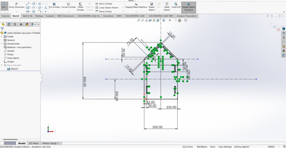
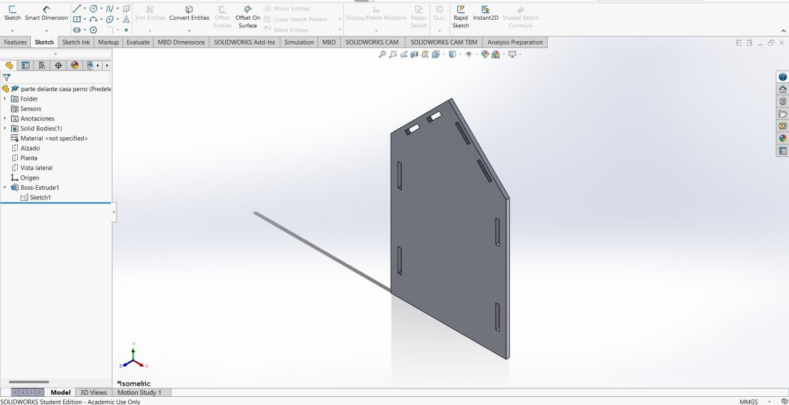
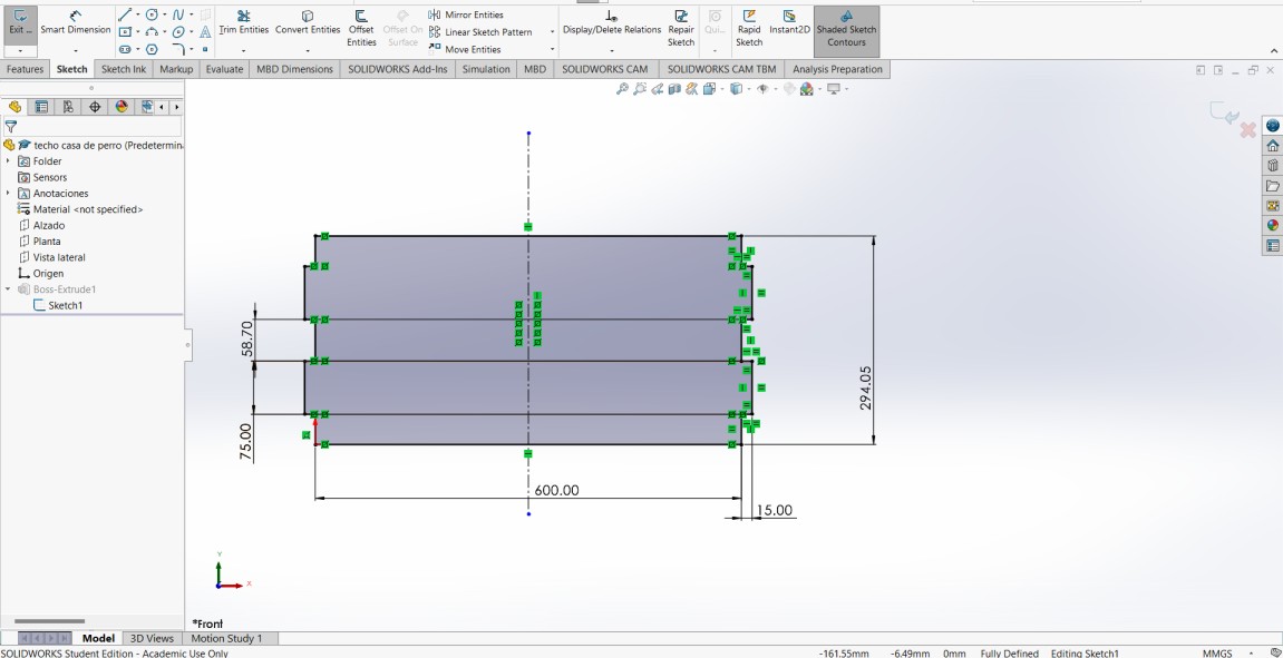
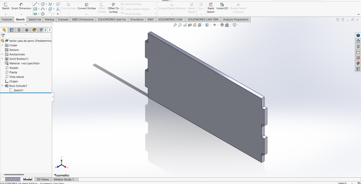
The front of the dog house was made with basic tools such as lines, arches, rectangular, mirror entities and constructive lines, this is the sketch and extrusion of 15 mm which is the width of the wooden board:
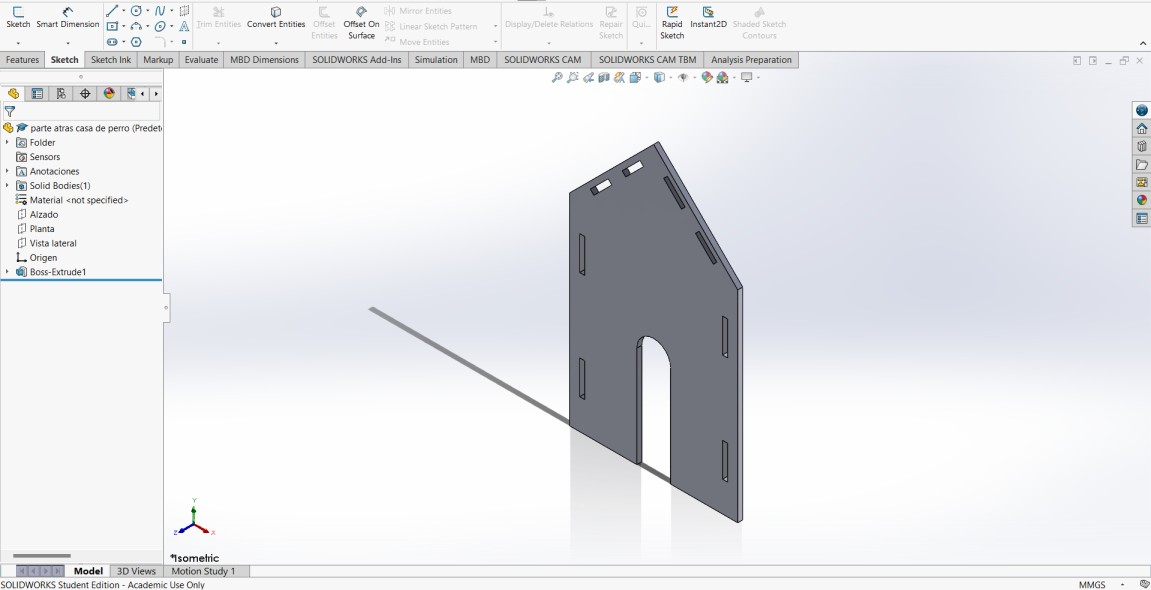
The back of the doghouse is almost identical to the front only that this does not have the "door" in between since in this part is sealed.
After I had the front and back I made the roof that the doghouse is going to have, this is the sketch:
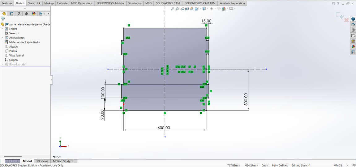
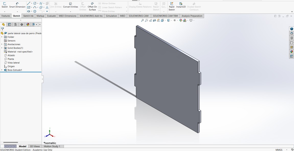
The last part of the dog house I need to design are the side walls, as in all the other pieces, they are quick strokes to make so I had no problem with the design.
With all parts of dog house designed I made an assembly in SolidWorks to see that everything dulls correctly and detect if there is a problem with this, as there is no problem, this is the final design of the dog house.
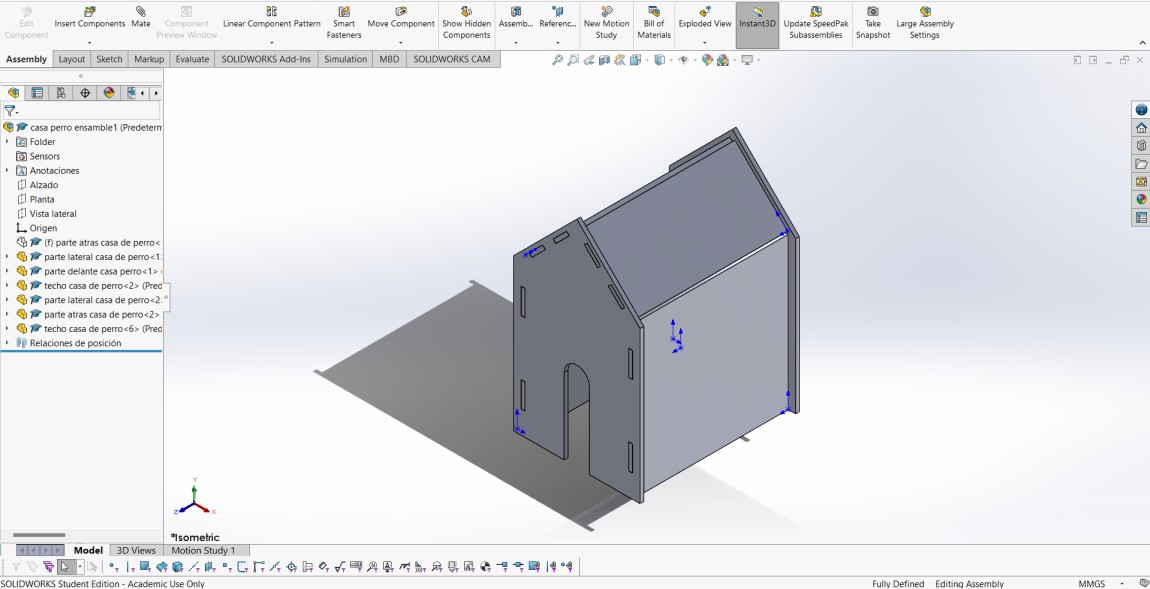
This is the final assemble
Knowing that the assembly is correct, I need to pass the pieces to format. DXF to make my CAM-toolpath.
Arrange the parts on the wooden table
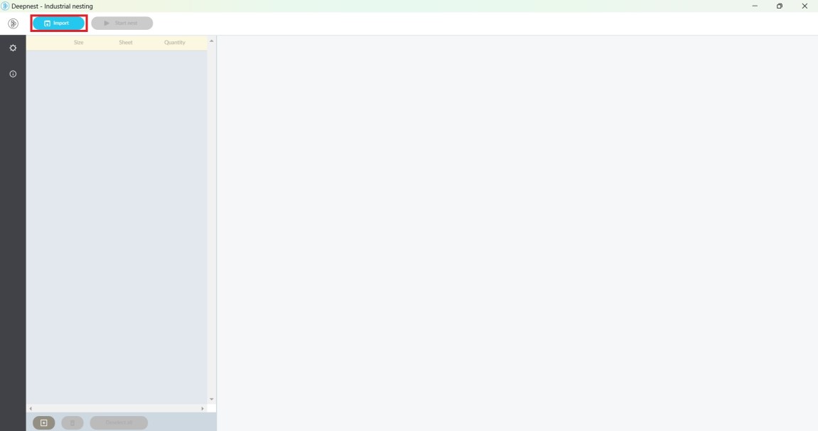
deepnest.io
Using the program Deepnest.io can put all parts together in . DXF and the same program could accommodate them from the best wood saving material.
To start using Deepnest.io I need to import the files I want to accommodate in format. DXF and place the number of times we want certain parts, in my case I want two side walls and two roofs for the dog house.
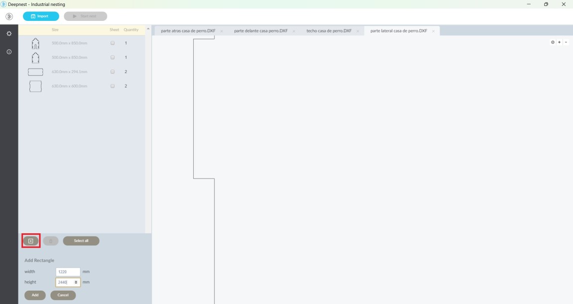
Having all the pieces, add a rectangle with the dimensions of the board you were going to cut, the units of that rectangle are in mm.
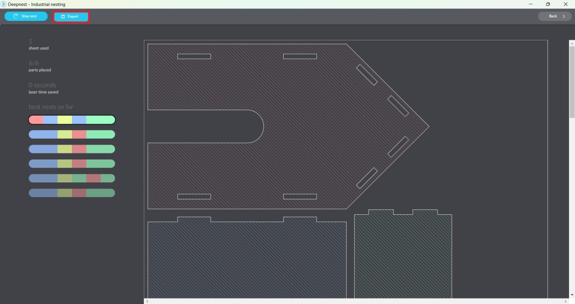
We start nest and select the accommodation that we like, when we finish selecting the accommodation we only export it as .DXF.
CAM-Toolpath
VCarve
For the CAM-toolpath I used VCarve software. VCarve allows users to create embossed and engraved designs with ease. It provides intuitive design tools to create 2D and 3D designs quickly and accurately. In addition, it offers a wide range of machining tools, such as embossing, engraving, contour cutting and perforation.
The only problem with this software is that only certain computers have it inside the university, so its use has to be very fast so that we can all fulfill this assignment.
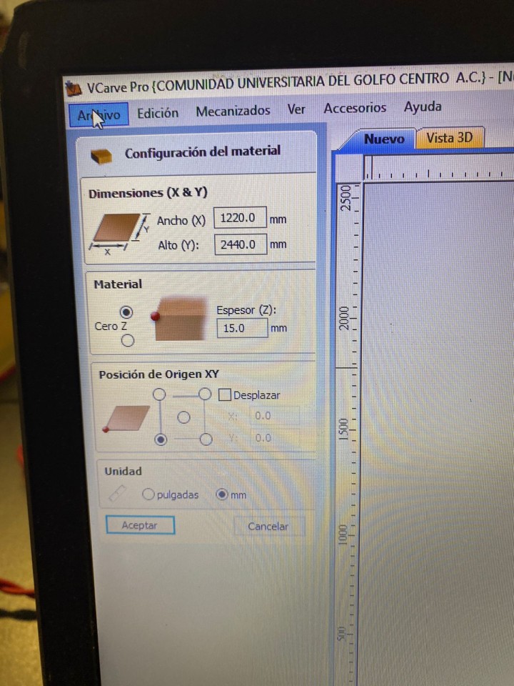
When opening the VCarve on the designated computer, the file must be imported. DXF that we will occupy to cut and adjust the size of the material we will occupy, in my case 1.22mx2.44m with 15mm thickness, once put the values of the material and units give in OK to continue.
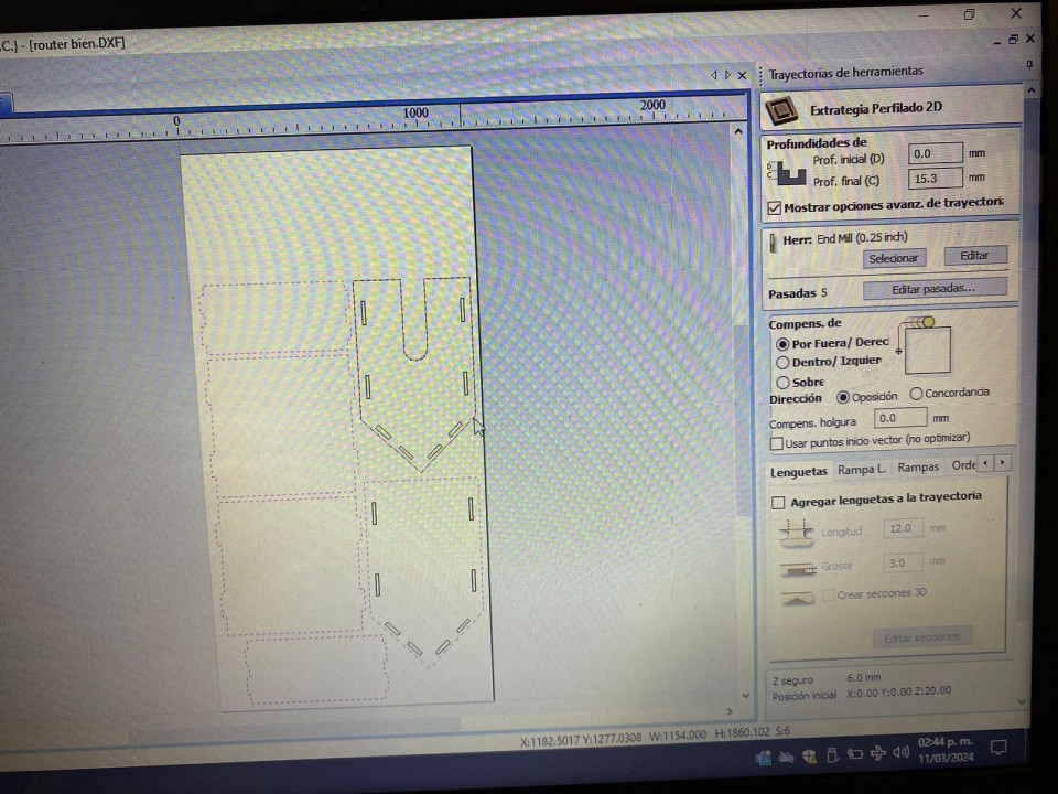
Then, we select the parts that are going to be internal cuts, these are going to be the first to be cut, because if not, it may not be well cut by the movement of the wooden board and being the first, the wooden board will be fixed enough for such a mistake to occur. After the internal cut, the external cut must follow.
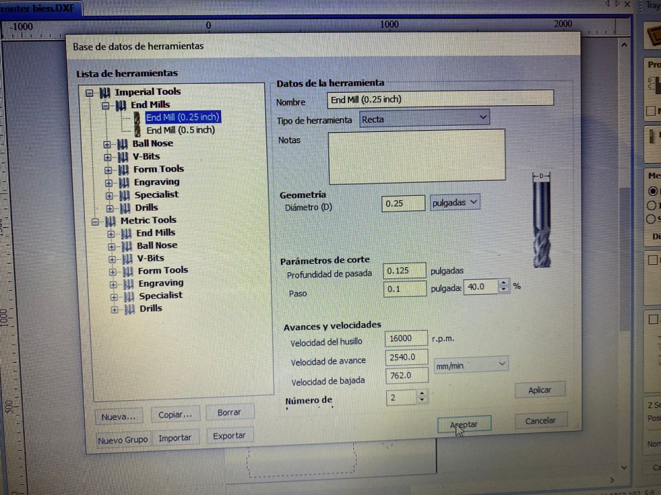
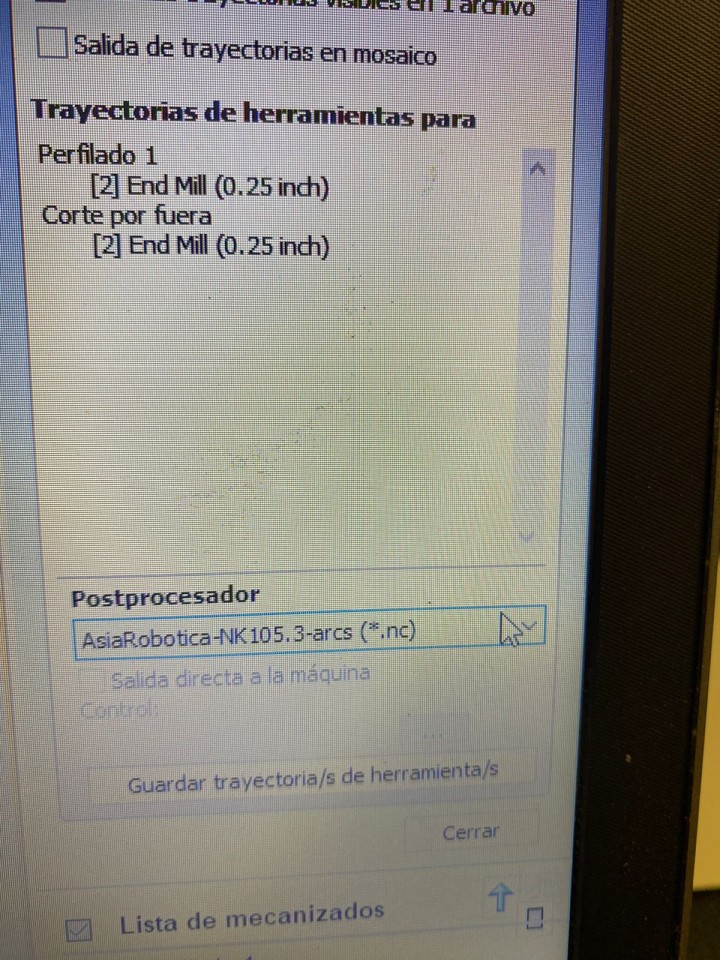
Having already defined the type of cut that will be each, we have to configure the tool that we will occupy, the tool is an End Mills 0.25 inch drill and we adjust the spindle speed at 16000 r.p.m, the feed speed is 2540 mm/min, the drop speed is 762 mm/min, once you put the parameters we give OK.
Subsequently, it is necessary to add "dog bones" or "T bones" which are a slight modification of the cover, the hole where the assembly is tight and well adjusted.
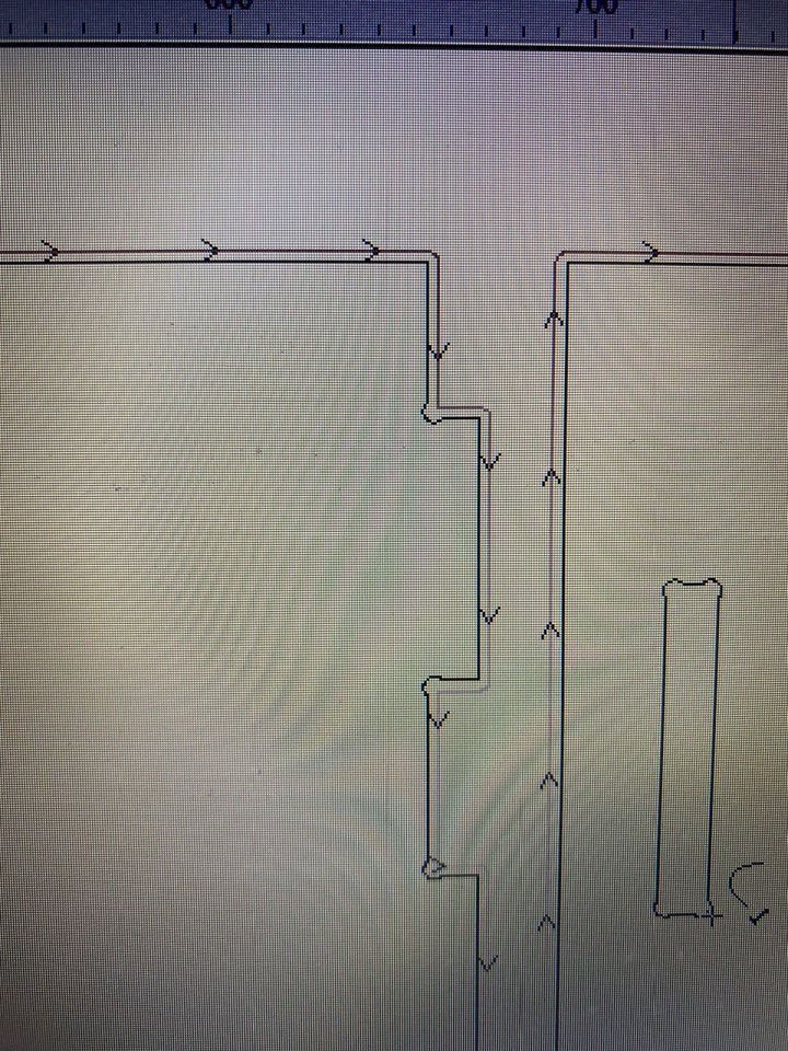
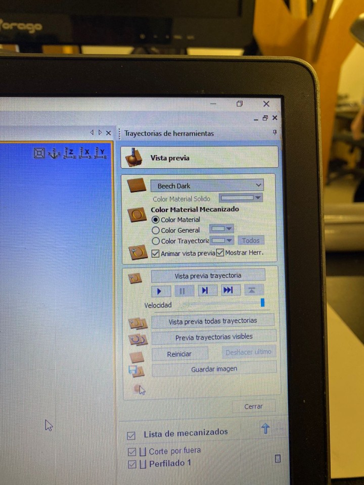
Before finishing, you have to do a trajectory simulation to see that the route is correct and there is no error.
Finally you have to save the archio in the format that the CNC machine we are going to occupy.
Machine
.jpg)
This is the CNC machine that I will occupy, is a generic machine made by the university, these are some of the specifications.
Note: As part of the safety training, two operators are required to handle the CNC machine by precaution.
- Dimension: 3x1.8x1.7mts
- Motor power: 4 HP at 24000 rpm´s
- Power Supply: 220v/2F/3.5KW
This is the interface of the software that controls the CNC machine, it is very intuitive and easy to use, I did not have many problems to use it.
.jpg)
First you have to import the file and calculate that all the parts that are going to be cut enter in their entirety, after it is necessary to establish the point of origin of the CNC machine. The function is ZERO.
.jpg)
Having everything already set up, you have to start cutting with the CNC machine, this should start the short apart from the origin that was given.
This is the CNC cutting
This is the CNC path
As seen in the previous video, the machine begins to cut the internal parts of the parts instead of the external parts, just as ordered.
Once the cuts are finished, it is necessary to remove the dust created during the cutting and also remove the excess material from the wood sheet so that it can be used in some other occasion.
.jpg)
After cleaning the place, this is how the cuts were made by the CNC machine.
.jpg)
At the time of removing the pieces of wood, some pieces were stuck together as shown in the following image, so I had to sand it so I could remove the damage from the piece.
.jpg)
This is the result of some of the parts after being sanded.
.jpg)
Finally, this is the dog house already assembled.
.jpg)
.jpg)
Some problems
In the modeling part I had no problem, because I use SolidWorks software a lot, but the problems I had was in the use of VCave software, being a software I did not know I had to learn fast and that made me have several mistakes, one of them was that in one piece I did not put dog bones and also I had not exported the file correctly and one last mistake was to detach the cut wood from its base since there were a few pieces of this in the final piece.
These problems were solved quickly, the piece that had not been given dog bone was cut again but now with this. For the file, I had to look for the type of file that can read the CNC that I was going to use, it took a long time but I found it. Finally, the surplus of the other pieces I removed with the help of a specific sandpaper for wood.
Now that I know the program better, most of these mistakes should not be repeated, as well as the cutting process.