6. embeded programming
Even though I had used arduino before I feel like I never really understood the basics of coding. This week was very good to understand the basic concepts and structure necessary for coding. I also had never used Python which I feel is interesting to learn.
Understanding your board
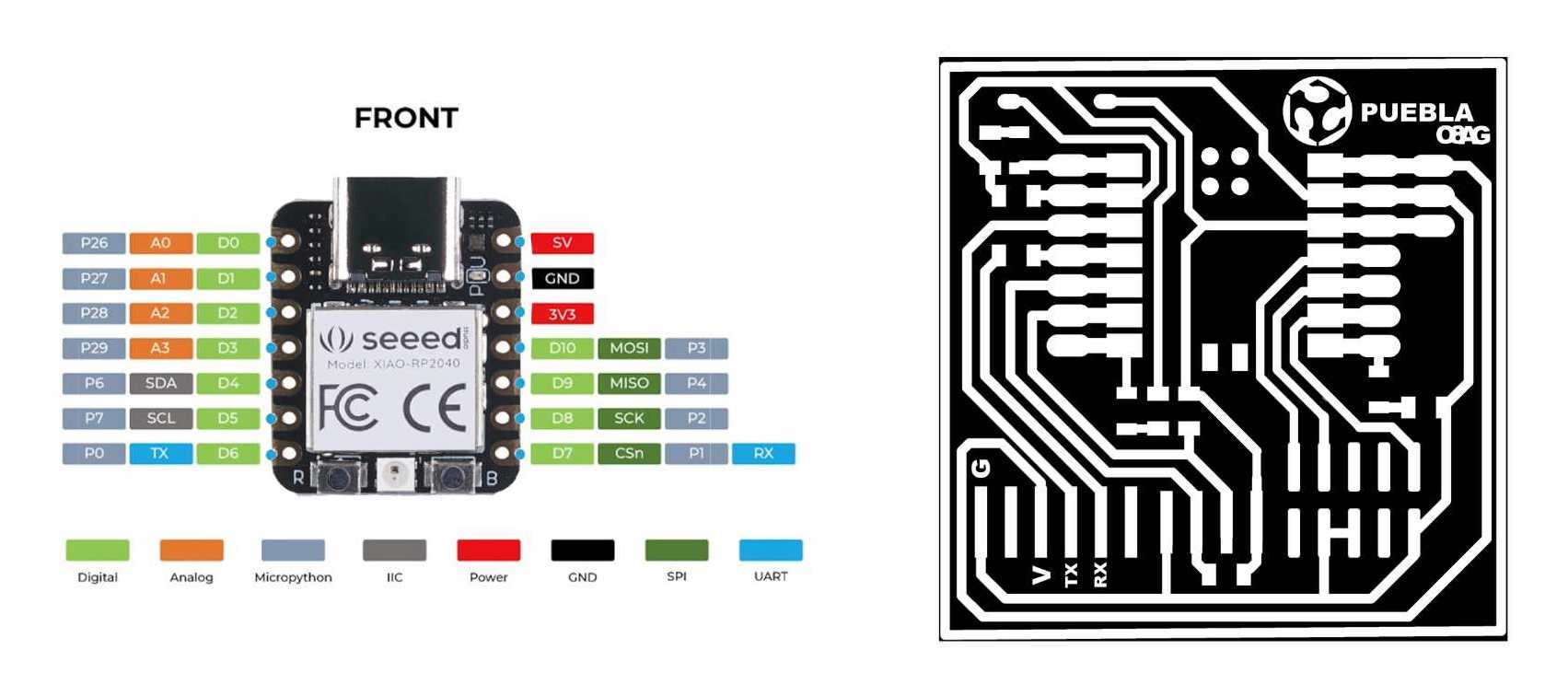
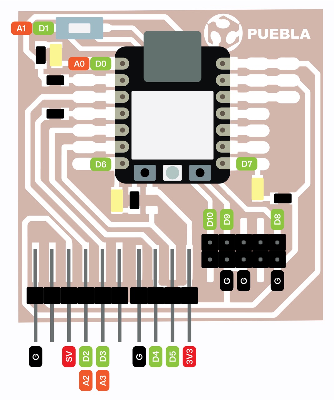
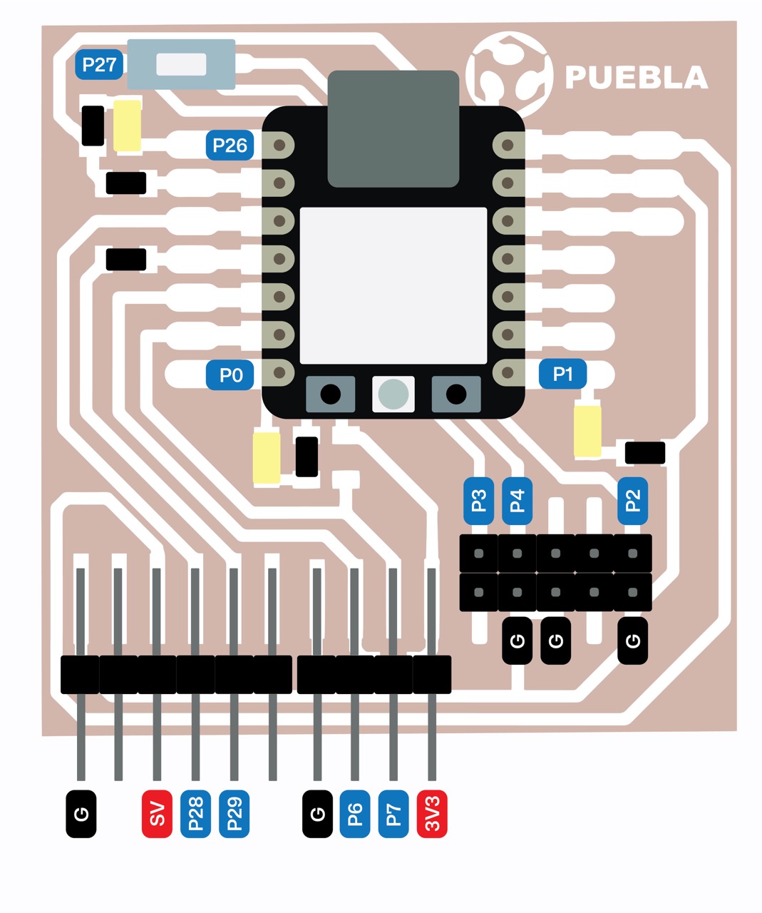
As a beginner and a visual learner, I prefer to keep things organized and clear. That's why I've created some diagrams that explain the function of each pin, making it easier to define them in my code. I've made one for Arduino (C++) and another for Python, using the pinouts of the XIAO - RP 2040 and the traces from our PCB production to identify each connection accurately.
Basic differences between C++ and Python
During our group assignment we learned some of the basic differences between C ++ and Python coding. Here you can find more detailed information about our practice.
Action |
C ++ |
Python |
|---|---|---|
| Variables | variables must be declared | variables do not need to be declared, it simplifies variable usage |
| If - Else condition | if (___) { ____ } else if (___) { ____ } else { ____ } | if ____: print(“____”) elif ___: print(“____”) else ___: print(“____”) |
| Functions | must specify the return type explicitly | functions are defined using the def keyword |
| Comments | // - for single line comments, /* comments */ - for multi-line comments | # - for single line comments, ‘’’ comments ‘’’ - for multi-line comments |
Platforms for coding
There are different platforms that are used for coding, I will be using:
Arduino for C++ coding
Mu Code for circuit python

First examples in class
Arduino
To begin with the basics, we learned how to write a program for our microcontroller board to make the three LEDs blink in sequence.
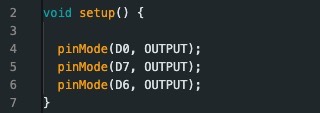
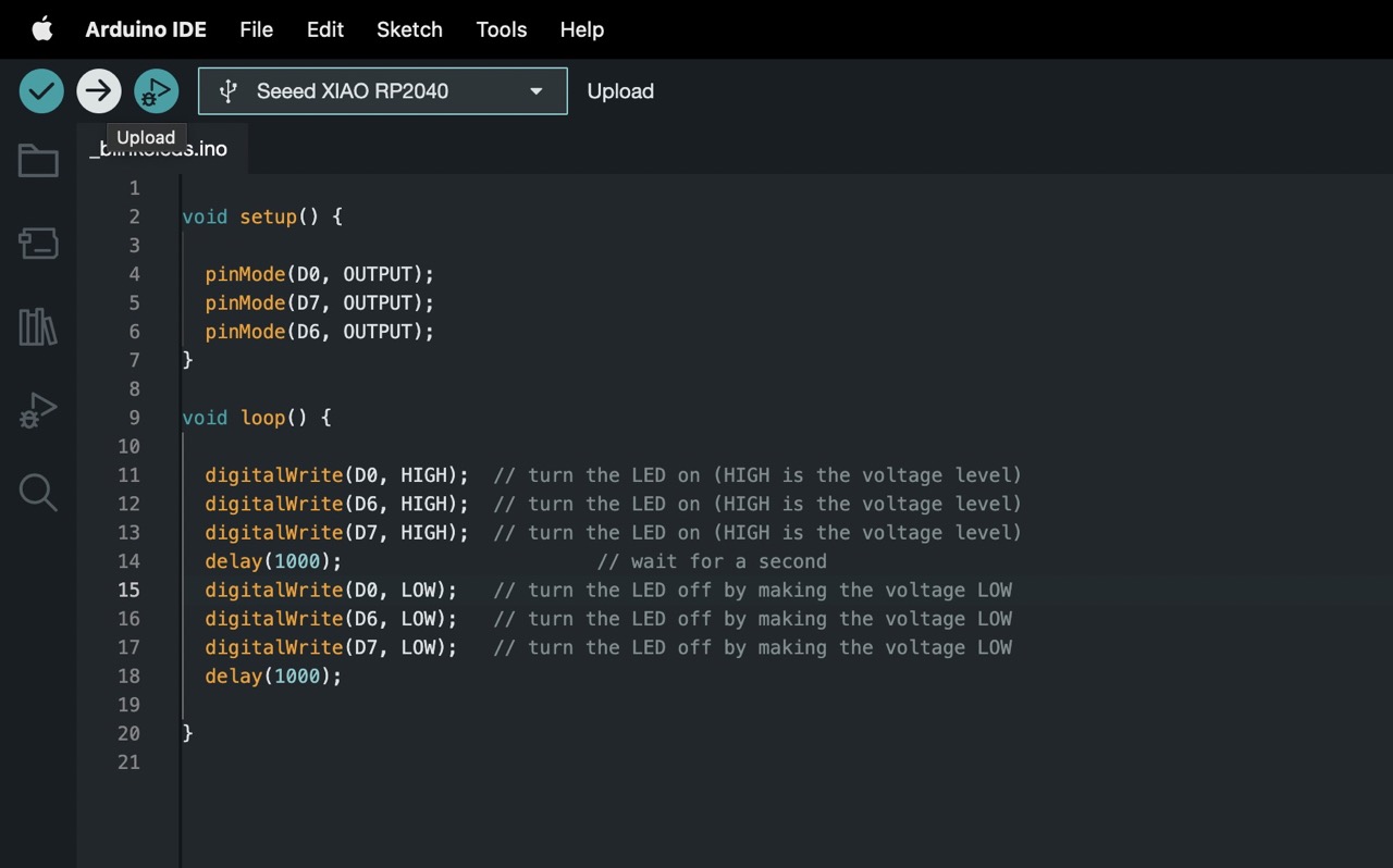
Firstly, we need to specify which pins on the microcontroller board are connected to the LEDs. This information can be found in the diagrams I created, which make it easy to identify the pin numbers. In our setup, the LEDs are connected to pins D0, D7, and D6. These pins need to be configured as outputs so that they can control the LEDs.
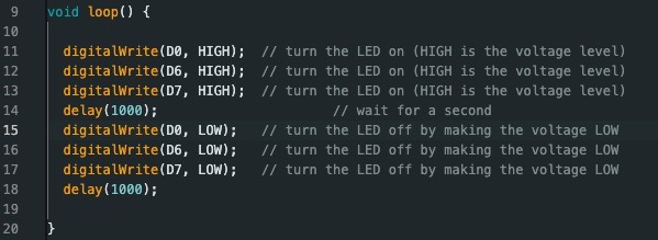
Next, within the void loop() function, which is the main execution loop of our program, we use the digitalWrite() function to control the LEDs. To turn an LED on, we use digitalWrite(PIN#, HIGH), where PIN# is the pin number of the LED we want to control. We then add a delay of 1000 milliseconds (1 second) using the delay(1000) function to create a visible pause before proceeding. After the delay, we turn off the LED by setting using digitalWrite(PIN#, LOW).
After finishing the code, we uploaded it to the microcontroller board using the 'upload' button. It's important to remember to always check that the correct board is selected before uploading the code.
CircuitPython
Setup Instructions:
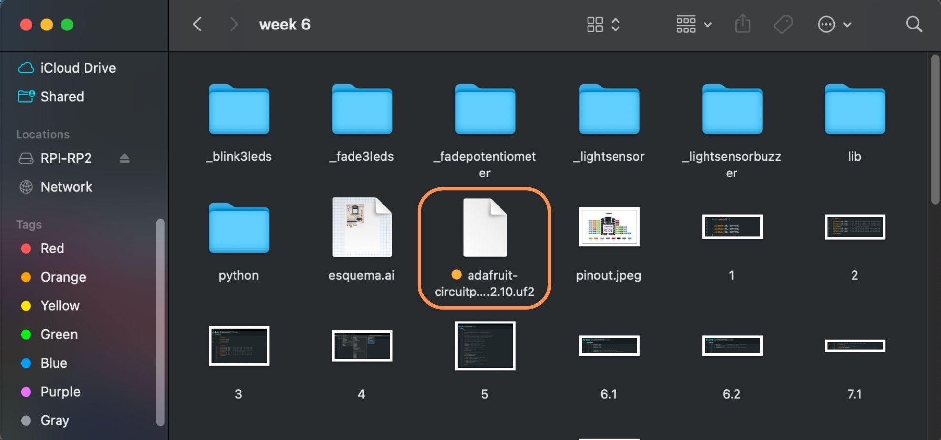
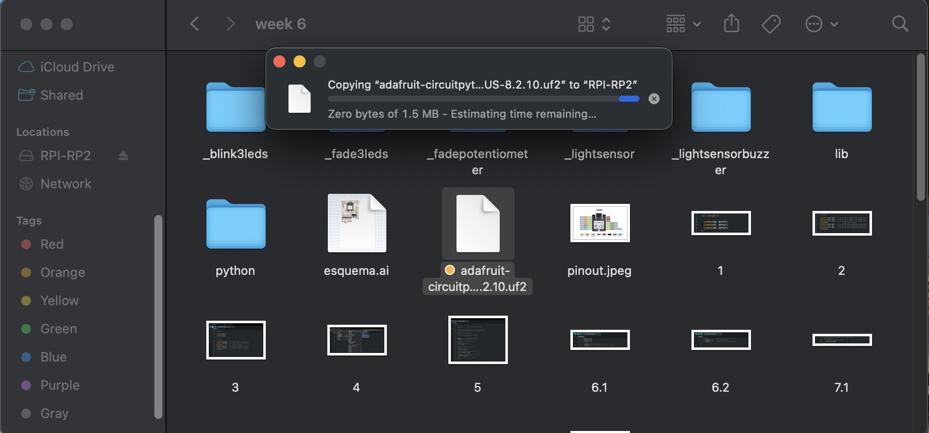
- Copy and paste the 'adafruit-circuitpy' file into the 'RPI-RP2'folder to enable the Xiao to be read by Python.
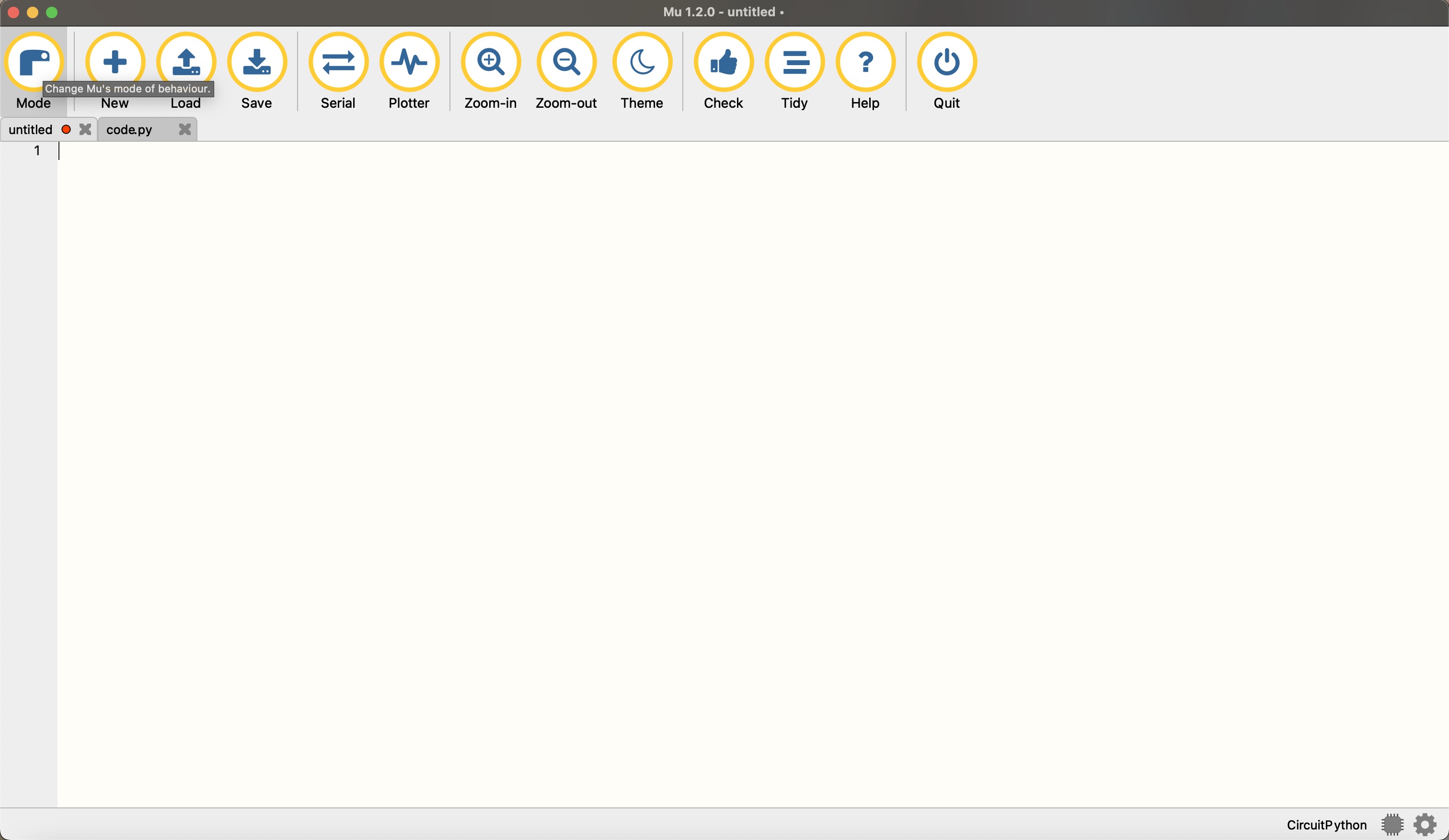
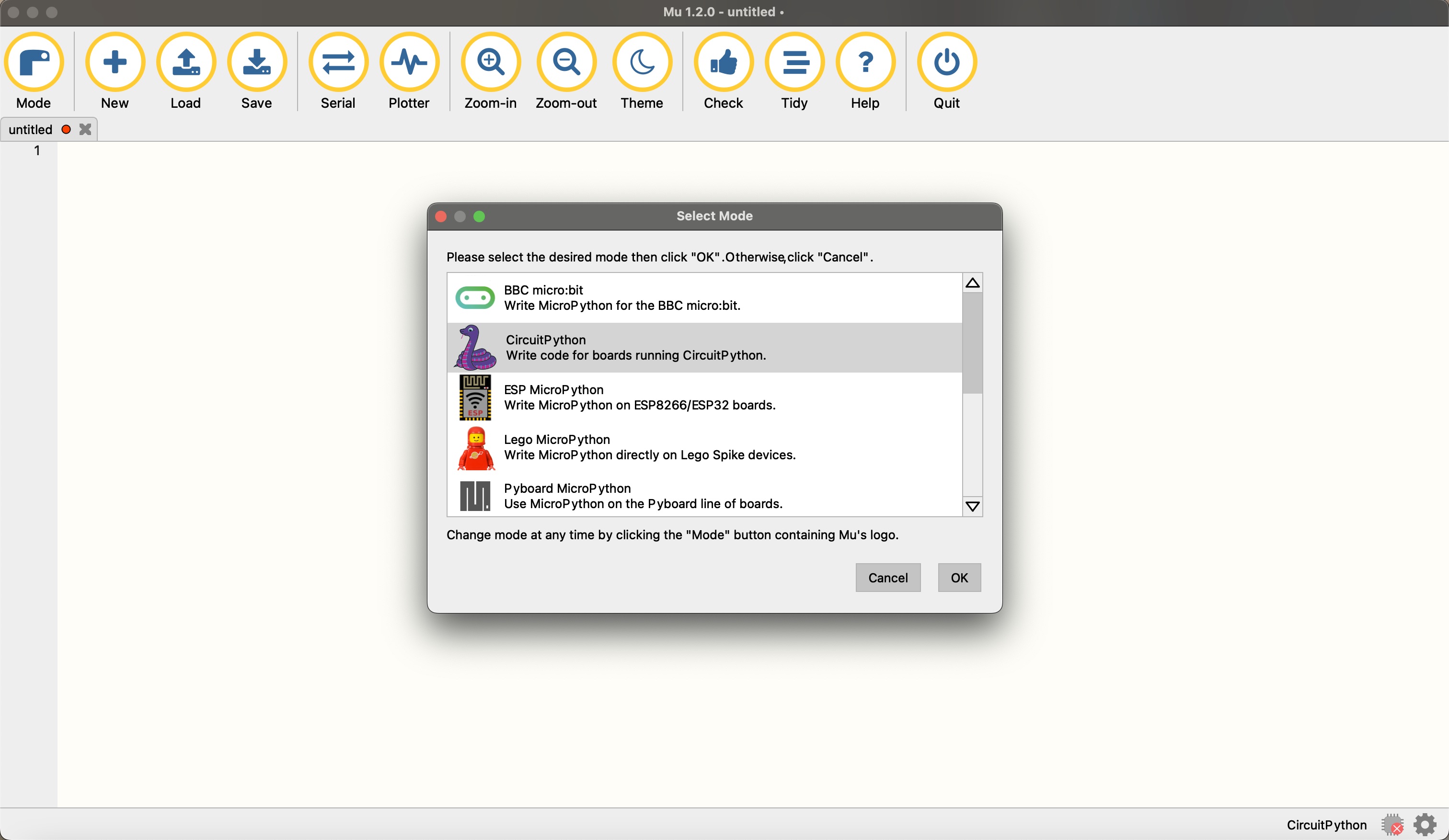
- Open 'Mu Editor' and click on the 'Mode' button. Select 'Circuit Python'.
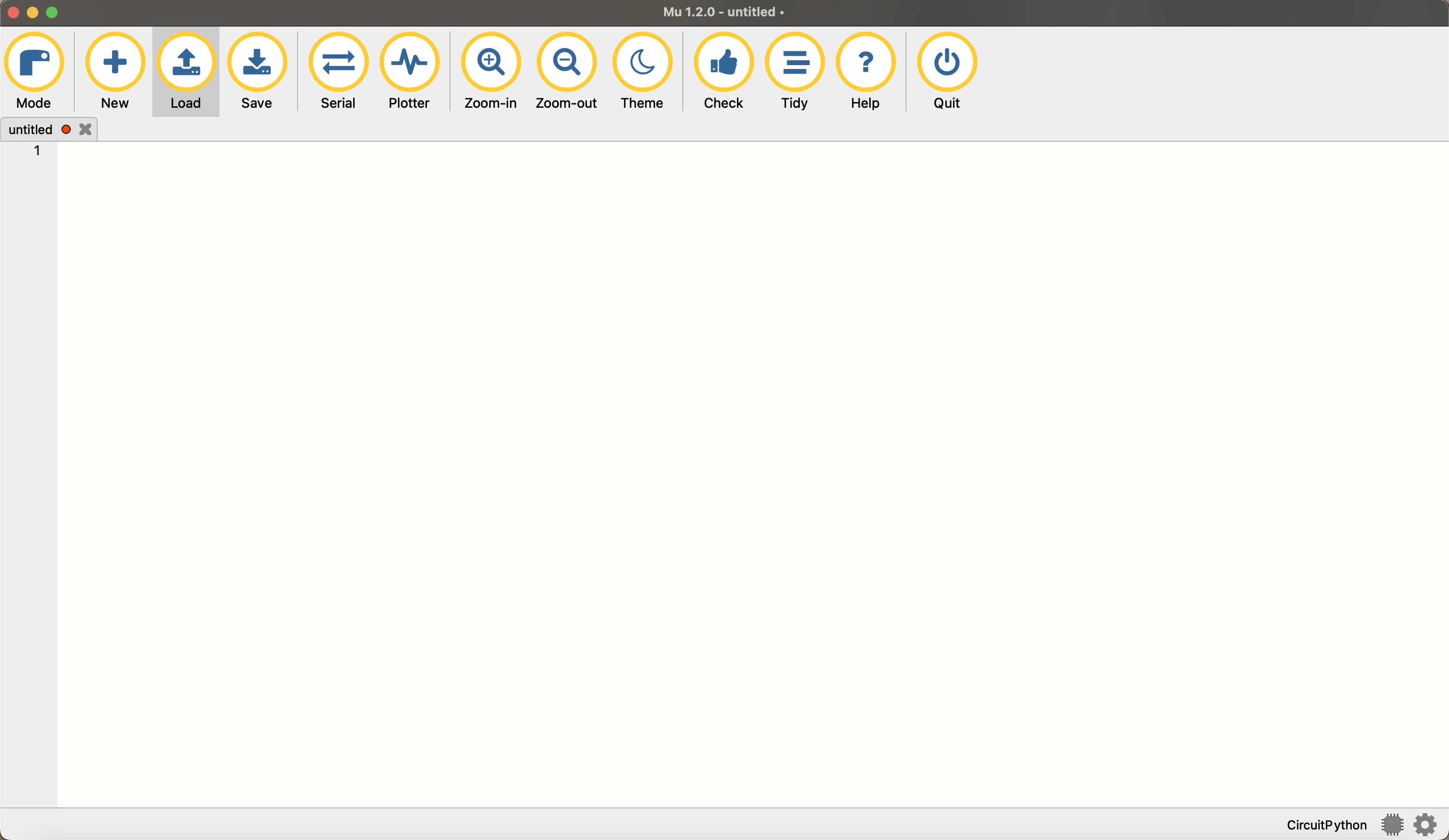
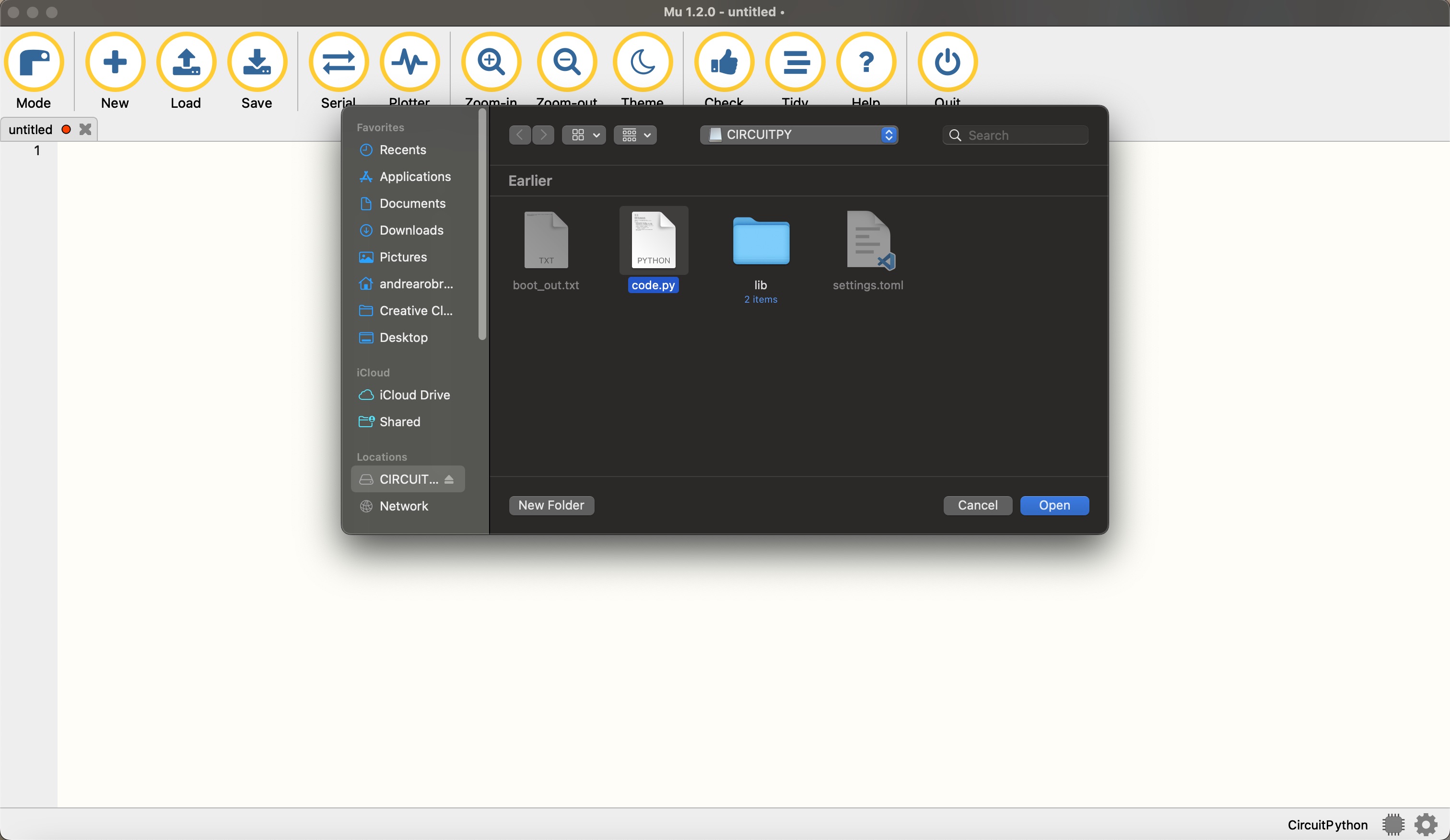
- Click on the 'Load' button and locate your 'Circuitpy' board. Then, open the 'code.py' file.
Now, lets write a code with python for our microcontroller board to make the three LEDs blink in sequence.
To start, the code imports necessary libraries: time for time-related functions, board for accessing board pins, and digitalio for controlling digital input/output pins.
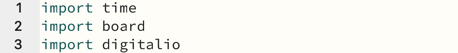
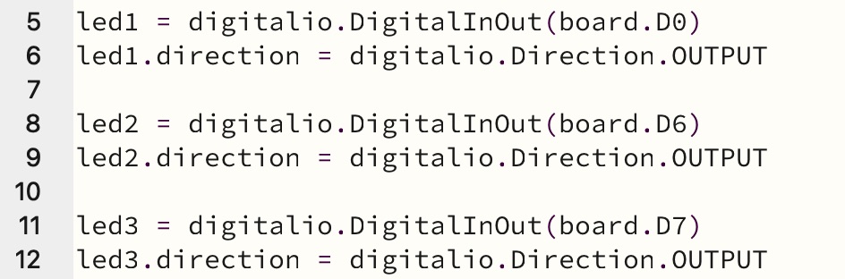
Then, three digital input/output objects are created, one for each LED, led1, led2, and led3 are initialized as outputs to control the LEDs connected to pins D0, D6, and D7 respectively.
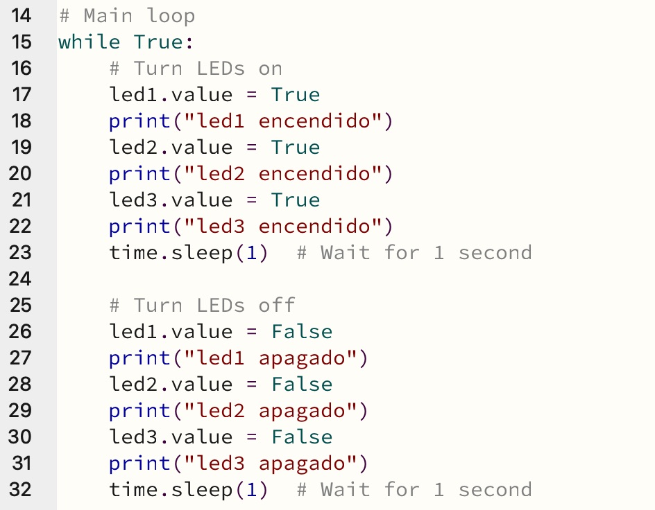
Under the main loop, the code turns on all three LEDs by setting their values to True. It also prints messages in the serial monitor indicating that each LED is turned on. A 1 second delay is included using time.sleep(1) before the LEDs turn off by setting their values to False and adding another 1 second delay before the loop continues.
Experimenting with codes
1: Fading LEDs
Arduino - C++ coding
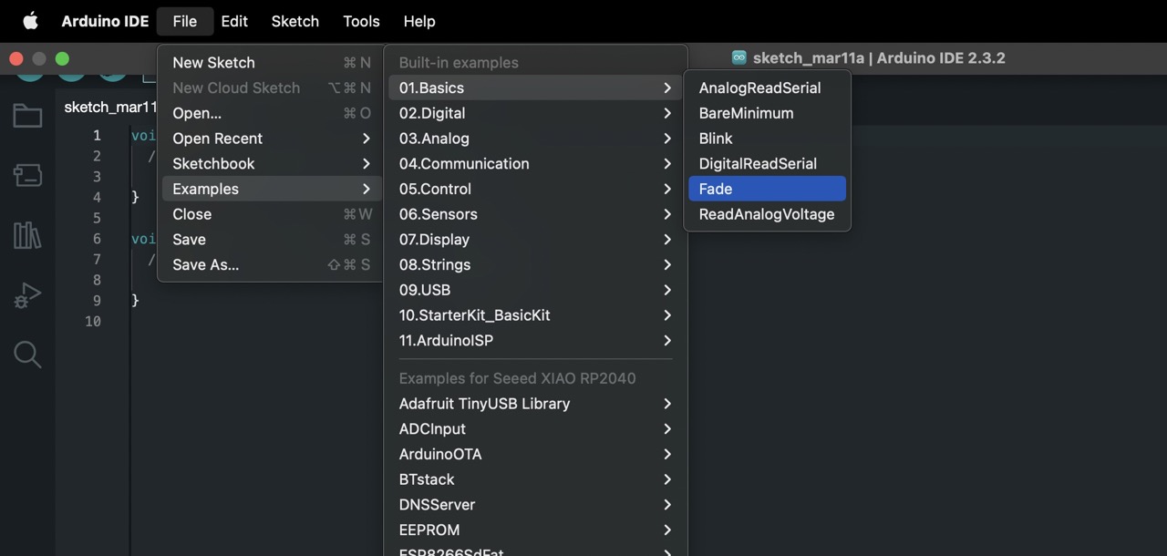
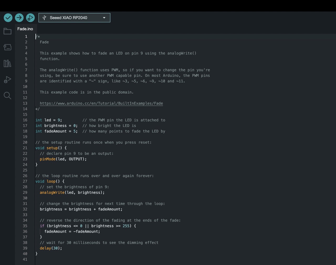
As a beginner in coding, I decided to explore the examples provided by Arduino to learn more about programming. I started by navigating to the 'File' menu, then 'Examples', and selected '01.Basics'. From there, I chose the 'Fade' example.
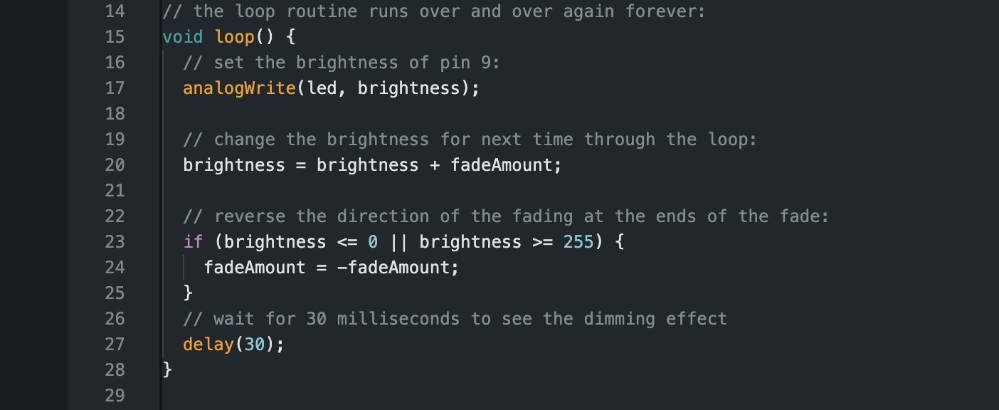
This example code demonstrates how to create a fading effect with LEDs. It provides a pre-generated code that gradually changes the brightness of an LED.
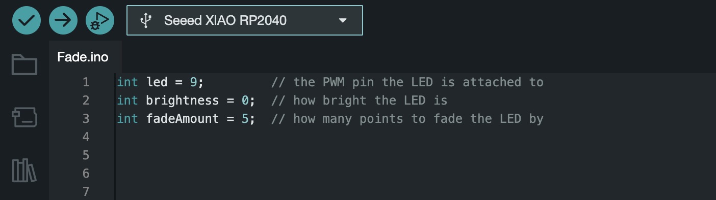
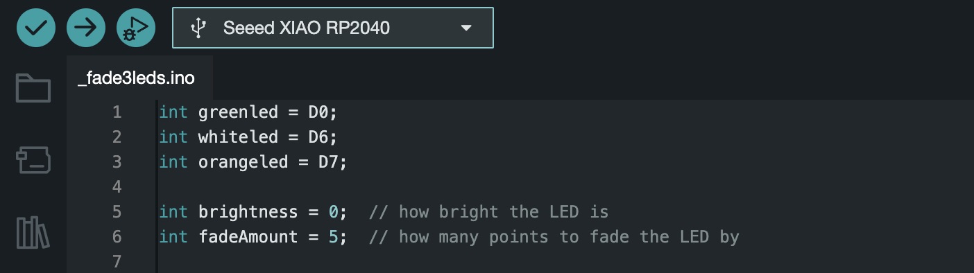
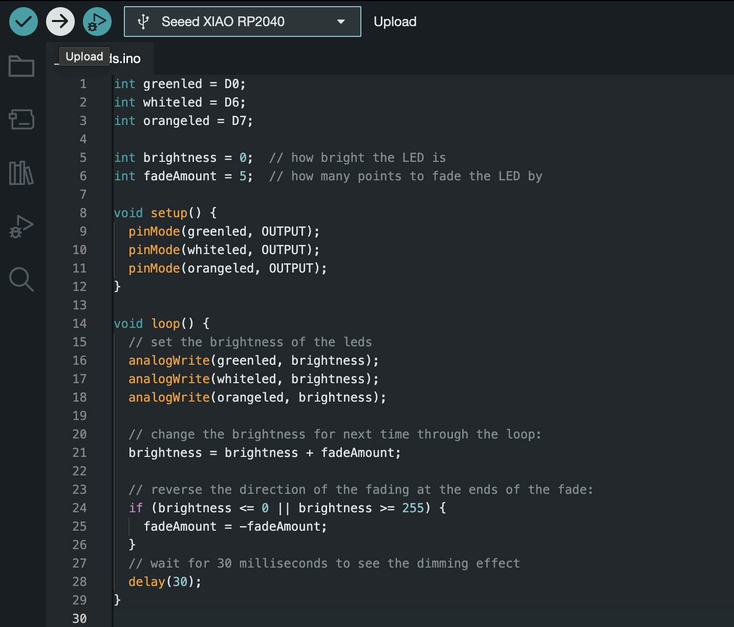
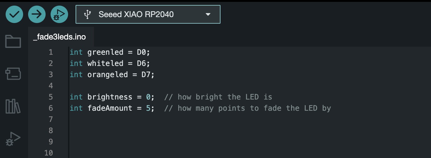
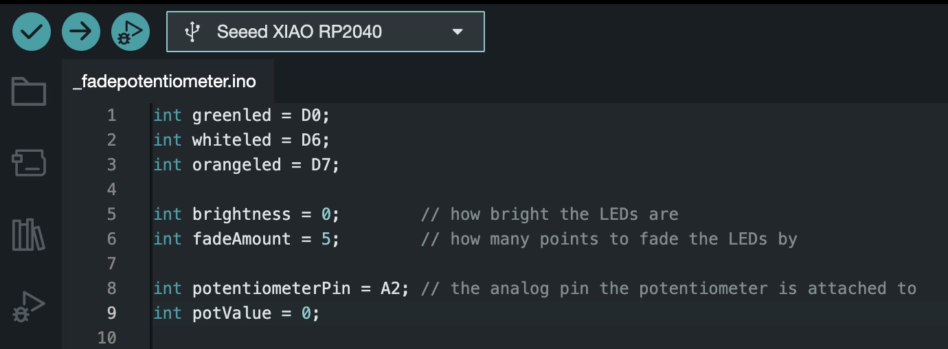
Using this code as a starting point, I began modifying it to suit my specific needs. First, I included all of my LEDs by specifying the pin numbers each one of them is connected to. I kept the variables 'int brightness' and 'int fadeAmount' the same.
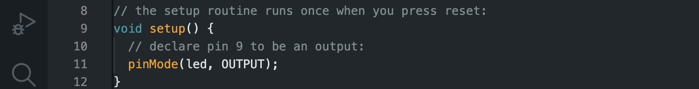
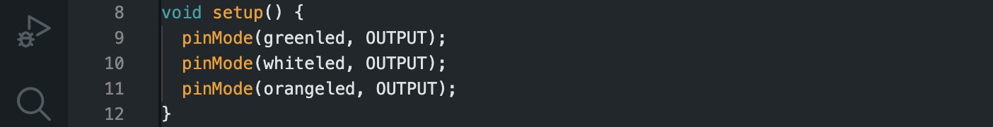
Next, in the 'void setup' section of the code, I declared my three LEDs as outputs.
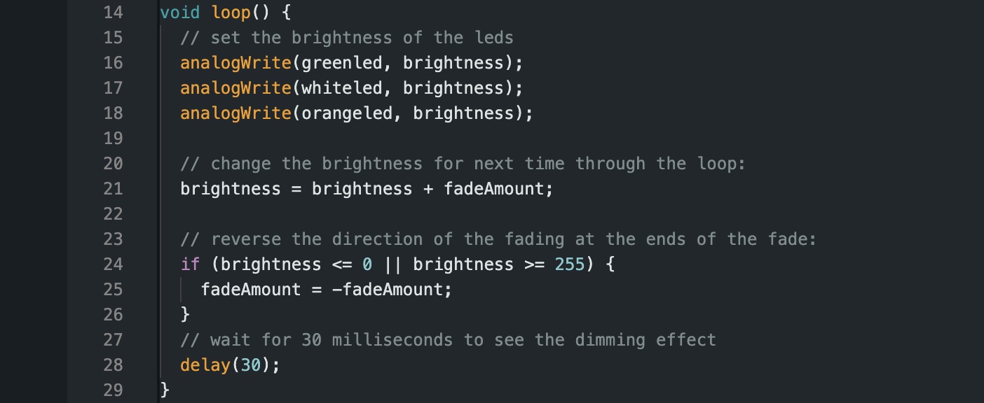
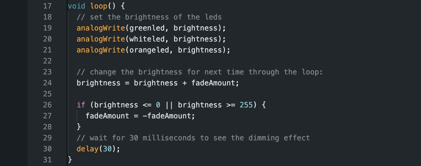
Finally, in the 'void loop' section, I wrote the code to set the brightness of the three LEDs.
Once the modifications were complete, I uploaded the code to my microcontroller board, this allowed me to see the code in action, with the LEDs displaying the desired fading effect.
Mu Editor - Circuit Python coding
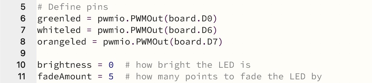
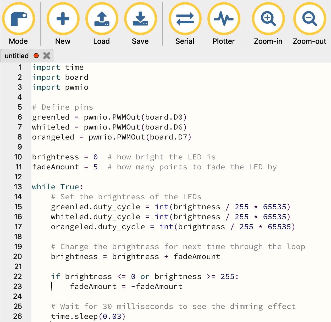
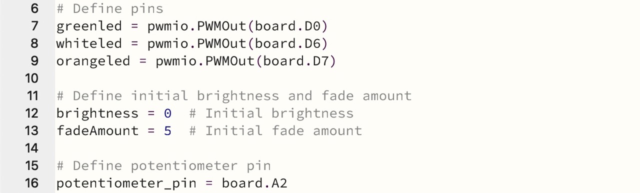
To start, the code imports necessary libraries: time for time-related functions, board for accessing board pins, and pwmio for controlling pulse-width modulation (PWM) pins.

Three PWM output objects are created: greenled, whiteled, and orangeled, representing LEDs connected to pins D0, D6, and D7 respectively. Then, two variables are initialized: brightness to represent the brightness level of the LEDs initially set to 0. And fadeAmount, which indicates how much the brightness of the LEDs will change in each iteration of the loop, initially set to 5.
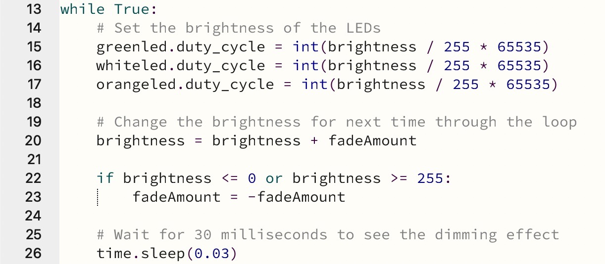
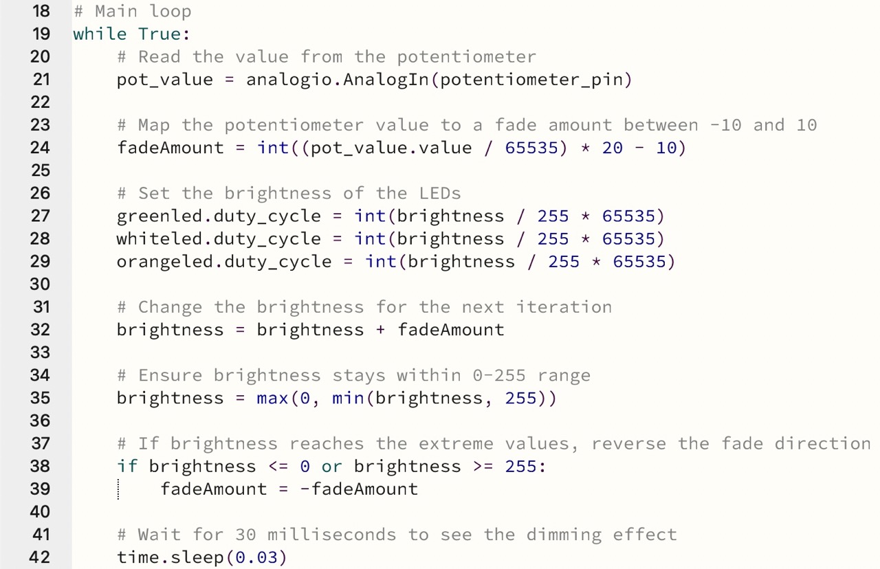
Under the “main loop (while True)” function the brightness of the leds are controlled using the duty_cycle attribute. After setting the LED brightness, the code adjusts the brightness variable by adding the fadeAmount. Finally, the code pauses execution for 30 milliseconds using time.sleep(0.03). This delay allows time to perceive the dimming effect as the brightness of the LEDs changes gradually.
Finally, the code is loaded to the microcontroller
2: Fading LEDs controlled with a potentiometer
I wanted to incorporate a potentiometer to the circuit to control of the fading effect.
Arduino - C++ coding
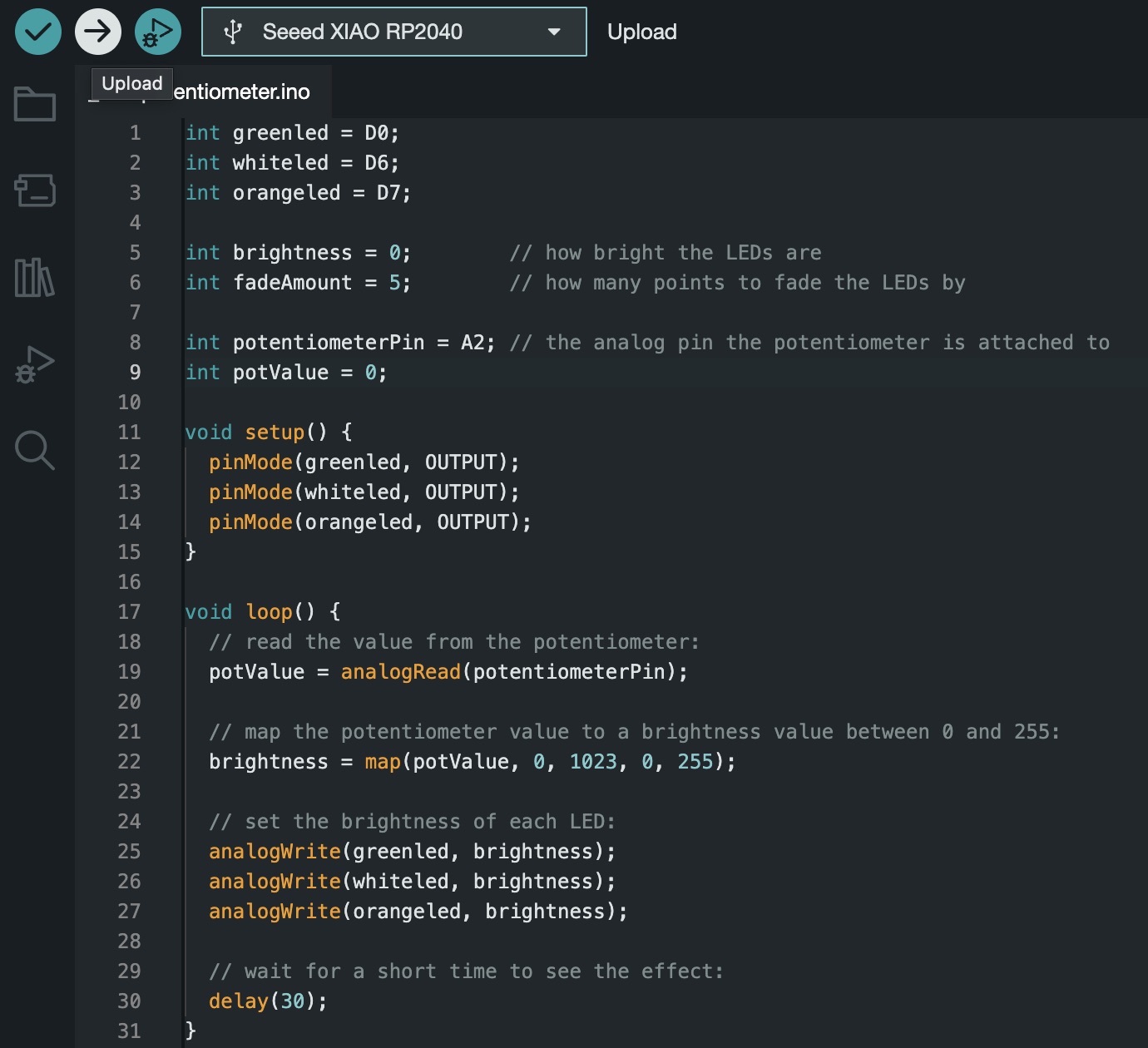
To begin, I added the potentiometer to the code by declaring a variable called 'potentiometerPin' and assigning it the value A2, which represents the analog pin connected to the potentiometer. Unlike digital pins that only read two states (HIGH or LOW), analog pins can read a range of values, making them suitable for devices like potentiometers. Additionally, I initialized a variable called 'potValue' and set it to 0 to store the current value read from the potentiometer.
Next, I left the 'void setup()' section unchanged because the LEDs used in the fading effect remained the same.

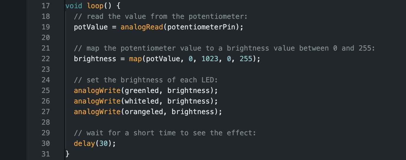
In the 'void loop()' section, I began by reading the value of the potentiometer using the command 'potValue = analogRead(potentiometerPin)'. This command reads the analog values from the potentiometer and stores them in the variable 'potValue'. To control the brightness of the LEDs based on the potentiometer's rotation, I used the 'map()' function. This function maps the values read from the potentiometer (ranging from 0 to 1023) to a new range suitable for controlling the brightness of the LEDs (ranging from 0 to 255). The syntax for this mapping is 'map(potValue, 0, 1023, 0, 255)'. This way, as I rotate the potentiometer, the value read from it is translated into a corresponding brightness level for the LEDs.
Finally, I uploaded the modified code to the microcontroller board to observe the effect of controlling the fading LEDs using the potentiometer.
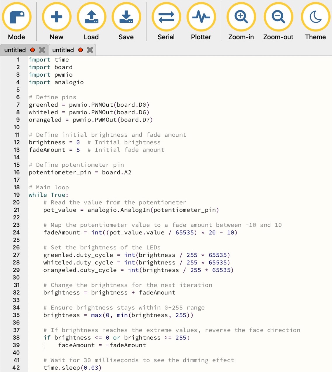
Mu Editor - Python coding
The analogio library was added for reading analog input from the potentiometer.

The (potentiometer_pin) was defined connected with pin A2.
Within each iteration of the loop, the code reads the value from the potentiometer connected to pin A2 using the analogio library. Then, this value is mapped to a fade amount between -10 and 10. This allows the user to control the fade speed of the LEDs by adjusting the potentiometer.
Finally, I loaded the code to the microcontroller board to observe the effect of controlling the fading LEDs using the potentiometer.
3: Light sensor
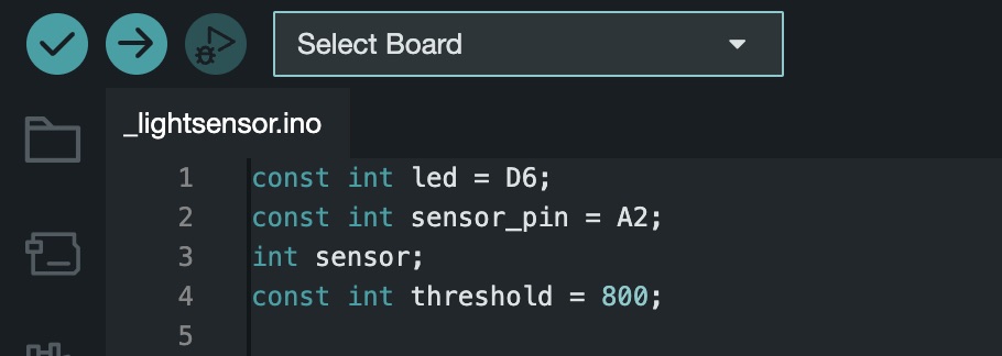
Arduino - C++ coding
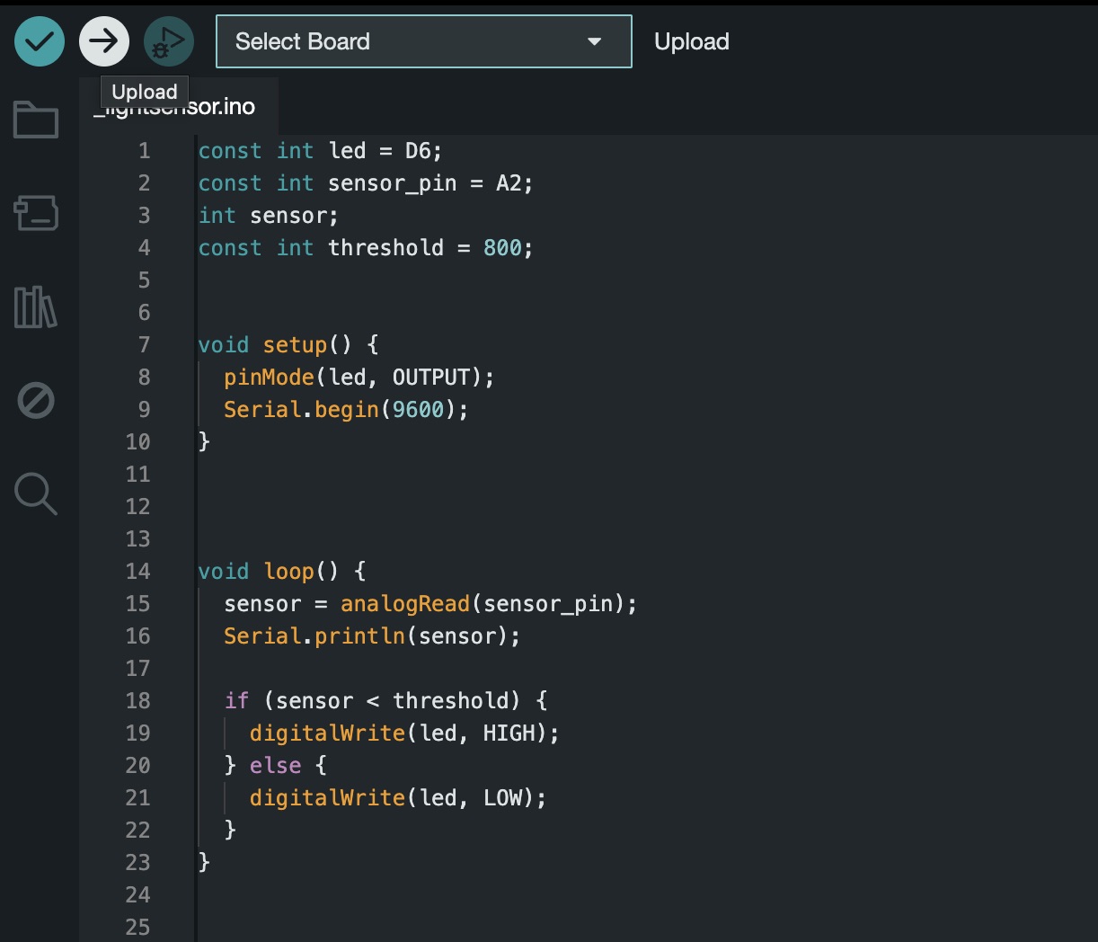
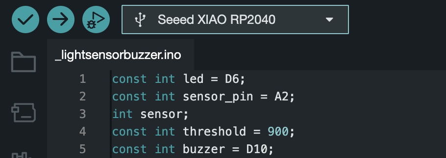
I began by defining the components to be used in the code. First, I declared the LED connected to pin D6 and the sensor connected to pin A2. Since the sensor provides analog data, I opted for an analog pin. Additionally, I initialized an integer variable named 'sensor' to store the sensor readings and set a threshold value.
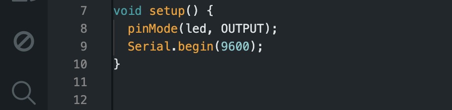
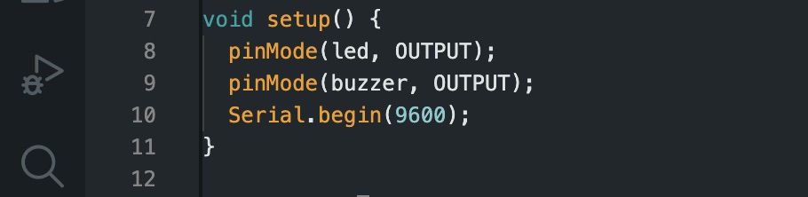
Then, under the “void setup” function, I configured the LED pin as an output to enable control of the LED.
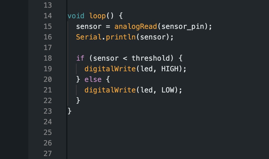
Within the loop function, I initiated the process of reading sensor values and displaying them on the serial monitor. Additionally, I implemented a conditional statement: if the sensor reading surpasses the threshold, the LED illuminates; otherwise, it remains off.
Finally I uploaded the file to my microcontroller.
*NOTE:
You can check the values of the sensor in the serial monitor and adjust the threshold value to your specific needs.
Mu Editor - Python coding
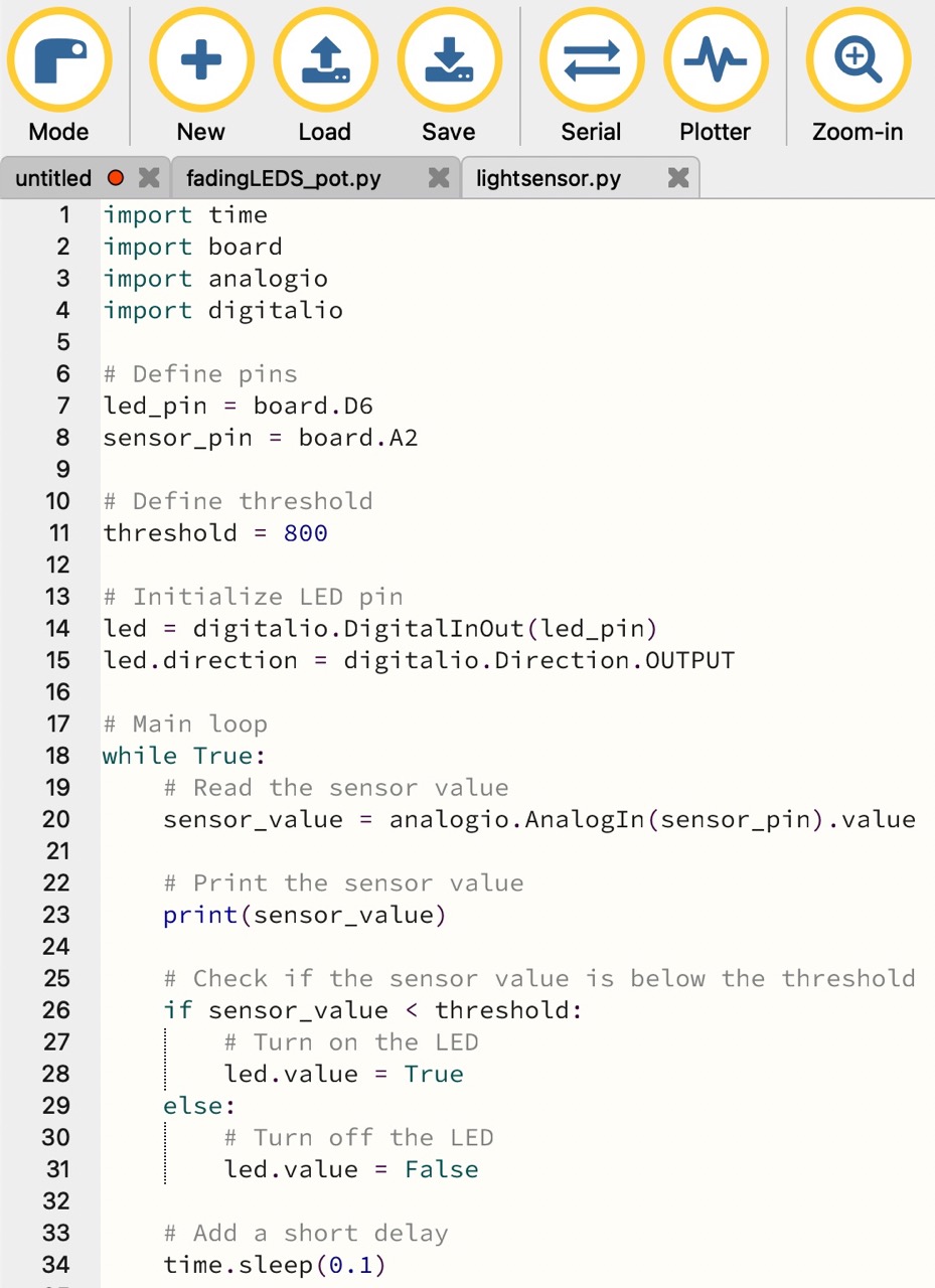
The code imports the necessary libraries, time for time-related functions, board for accessing board pins, analogio for reading analog input, and digitalio for controlling digital input/output pins.

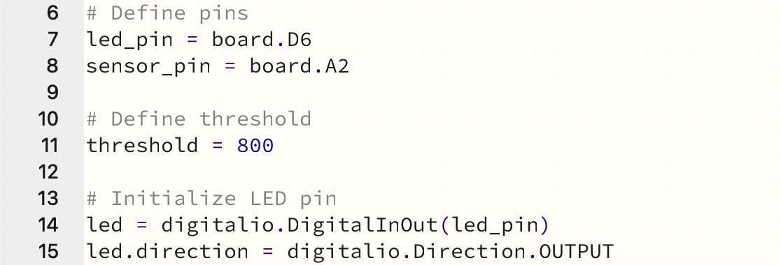
Then, the pins are defined for the LED (led_pin) D6 and the sensor (sensor_pin) A2. Additionally, a threshold value of 800 is defined. The LED pin (led_pin) is initialized as an output pin using digitalio.DigitalInOut(led_pin).
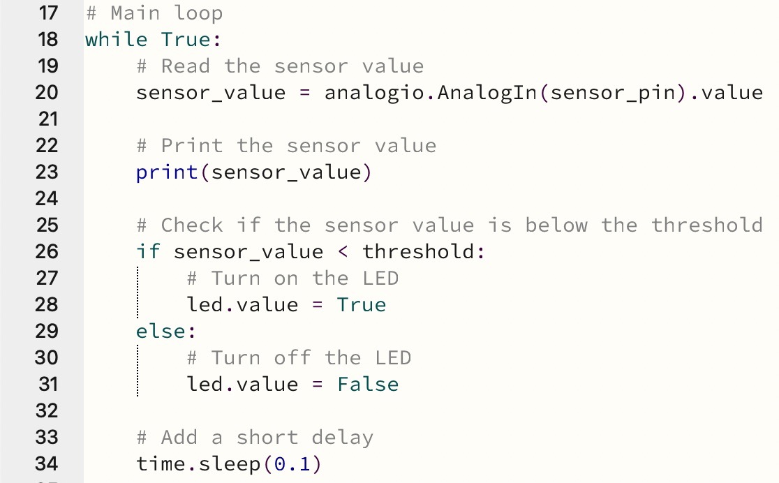
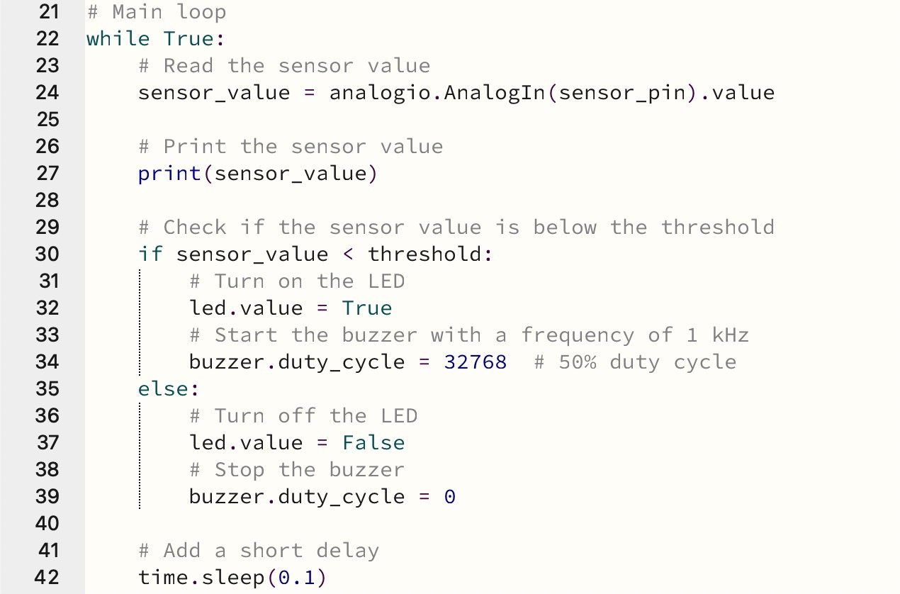
The code reads the value from the sensor connected to pin A2 using analogio.AnalogIn(sensor_pin).value. The sensor value is printed to the serial monitor using print(sensor_value). The code checks if the sensor value is below the predefined threshold. If the sensor value is below the threshold, it turns on the LED by setting its value to True (led.value = True). If the sensor value is equal to or above the threshold, it turns off the LED by setting its value to False (led.value = False).
Finally the code is loaded to the microcontroller.
4: Light sensor and buzzer
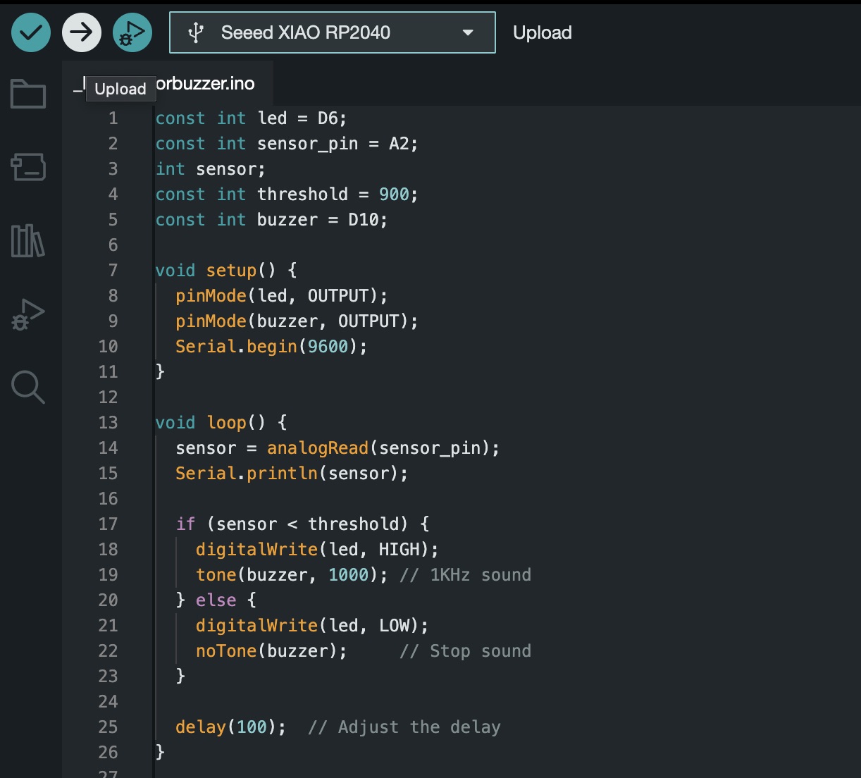
Arduino - C++ coding
An additional constant integer variable buzzer is declared, assigned to pin D10.
The buzzer pin (D10) is configured as an output pin to enable control over the buzzer along with the LED pin (D6).
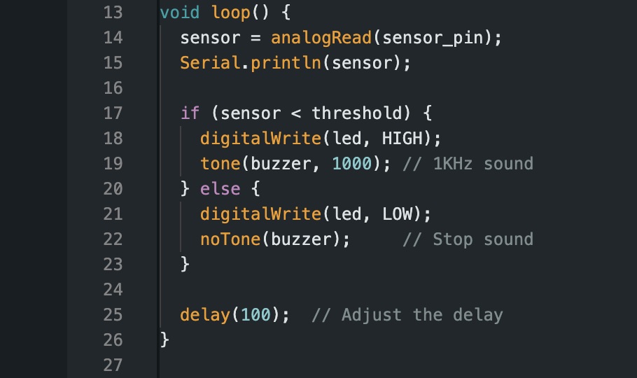
Under the “void loop” function a new function tone() is used to generate a tone on the buzzer. It is included within the conditional statement when the sensor reading falls below the threshold. The specified frequency of the tone is 1000 Hz. Additionally, the noTone() function is included to stop the sound when the sensor reading exceeds the threshold. Finally a delay value of 100 milliseconds is used to control the loop execution rate and adjust to the responsiveness of the system.
After uploading the modified code to the microcontroller, observe the behavior of both the LED and the buzzer in response to the light sensor readings. You can also adjust the threshold and delay values as needed for your specific application.
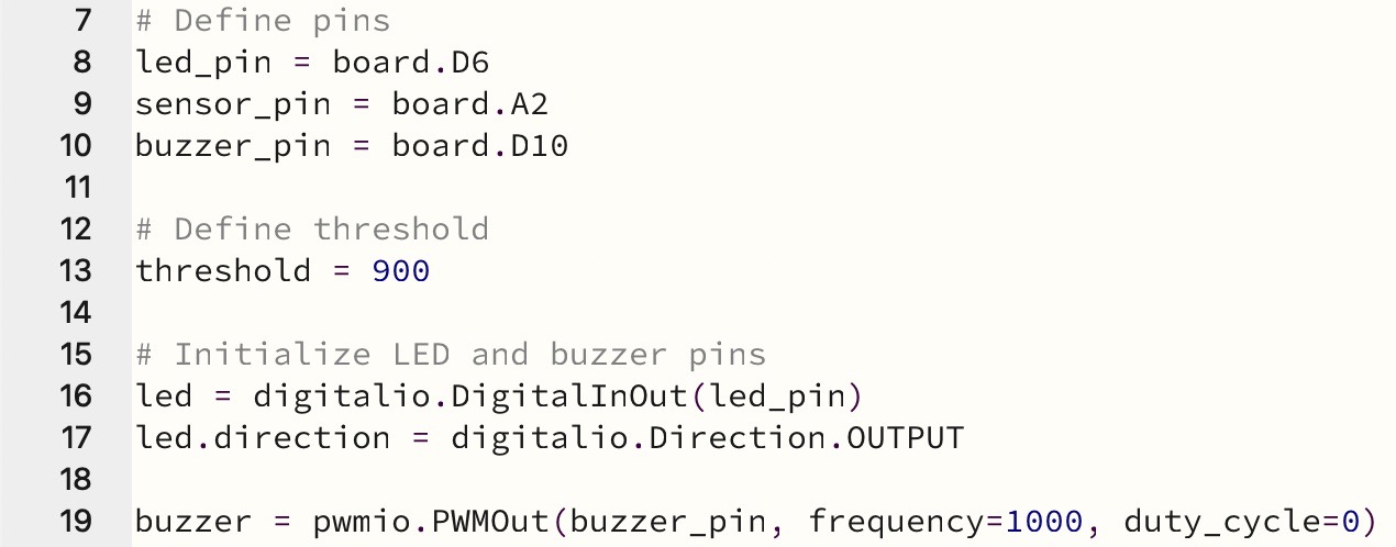
Mu Editor - Python coding
The pwmio library was added for controlling the buzzer with PWM output.

The buzzer pin (buzzer_pin) is assigned to D10 and it is initialized as a PWM output PWMOut(buzzer_pin, frequency=1000, duty_cycle=0). This allows for control over the buzzer.
The buzzer is included in the conditional statements: If the sensor value is below the threshold, the buzzer is started with a frequency of 1 kHz by setting its duty cycle to 50% (buzzer.duty_cycle = 32768). If the sensor value is equal to or above the threshold, the buzzer is stopped by setting its duty cycle to 0 (buzzer.duty_cycle = 0).
Finally the code is uploaded to the microcontroller.

Files
- Arduino: 3 blinking leds
- Circuit python: 3 blinking leds
- Arduino: Fading leds
- Circuit python: Fading leds
- Arduino: Fading leds and potentiometer
- Circuit python: Fading leds and potentiometer
- Arduino: Light sensor
- Circuit python: Light sensor
- Arduino: Light sensor and buzzer
- Circuit python: Light sensor and buzzer