5. 3D scanning and printing
This week was a tough one for me, my goal was to design a chain-like structure with a Voronoi texture. To achieve this, I watched several YouTube videos demonstrating similar textures on various geometries. Unfortunately, I struggled to replicate the exact texture I had in mind. However, I came across a webpage that could generate the texture when provided with my .obj file. Upon receiving the textured file, I realized that it would require extensive supports for 3D printing. For this reason, I decided to create a flower vase with a voronoi-like texture instead. I was also impressed by the quality and simplicity of the 3D scanning process. It exceeded my expectations, and I am eager to incorporate it into my design projects regularly.
3D printing
The assignment was to design and 3D print an object that could not be easily made subtractively. I've always had a fascination with futuristic textures and designs, particularly voronoi patterns. However, achieving these intricate textures through subtractive manufacturing is extremely difficult due to their organic nature and the mathematical complexity involved in creating the voids.
Important things to consider while designing for 3D printing
Printing area dimensions:
- The available printing area dimensions may vary across different printers, so make sure the object you are designing will fit under those dimensions to avoid issues.
Flat base:
- Incorporate at least one flat side into your object design to facilitate stable printing from that surface.
Overhang rule:
- Minimize overhangs in your design, these are sections or parts of the model that are extruded without material beneath them. If unavoidable, consider implementing support structures to ensure successful printing.
Printing angle:
- Keep angles below 45 degrees to avoid the need for additional support structures.
Bridging:
- It involves connecting two parts/sections of a print without support beneath, shorter distances have better results and are easier to print successfully.
Dimensions:
- It is important to account for potential material shrinkage or printer calibration discrepancies when designing joint pieces or components. Adjust dimensions accordingly to accommodate these factors.
Clearance:
- Maintain a clearance of approximately 0.2mm to 0.5mm between support structures and the printed part to prevent any unwanted adhesion or interference during printing.
To find more information about the different types of 3D printing technologies as well as printing materials, go to the group assignment page.
First ideas and complications
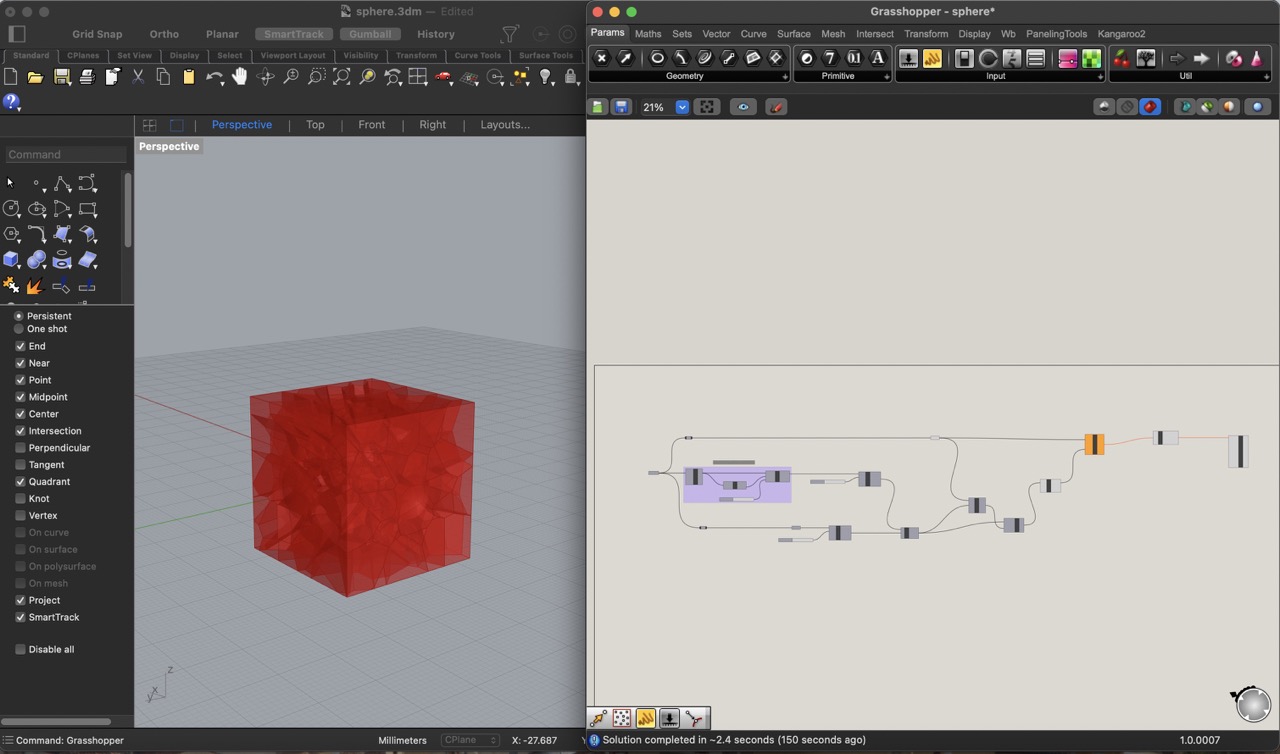
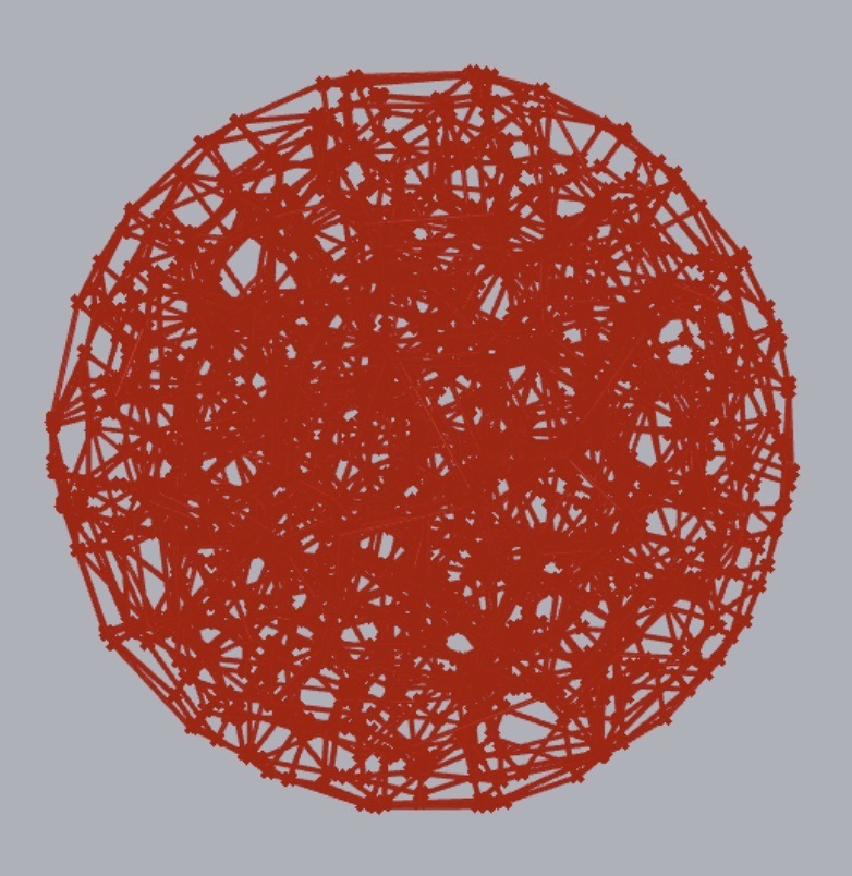
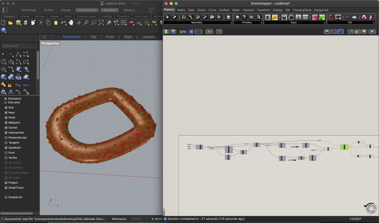
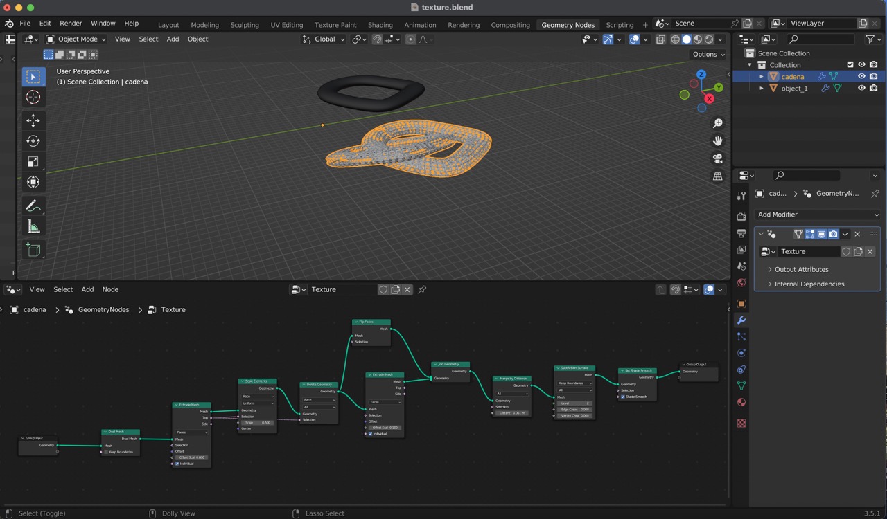
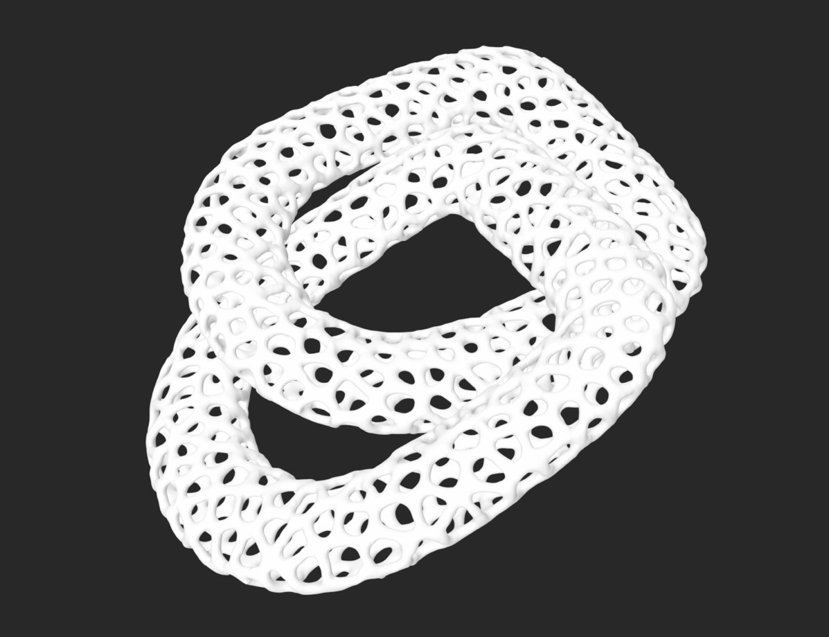
I wanted to design a voronoi textured chain suitable for jewelry or for creating molds through lost wax casting. To accomplish this, I began exploring Grasshopper as well as Blender and watching various YouTube tutorials to achieve the desired texture. However, I encountered some frustration as I struggled to create the exact texture I envisioned. My limited knowledge of the software made it challenging to identify potential errors or tailor the design to fit my specific geometric requirements.
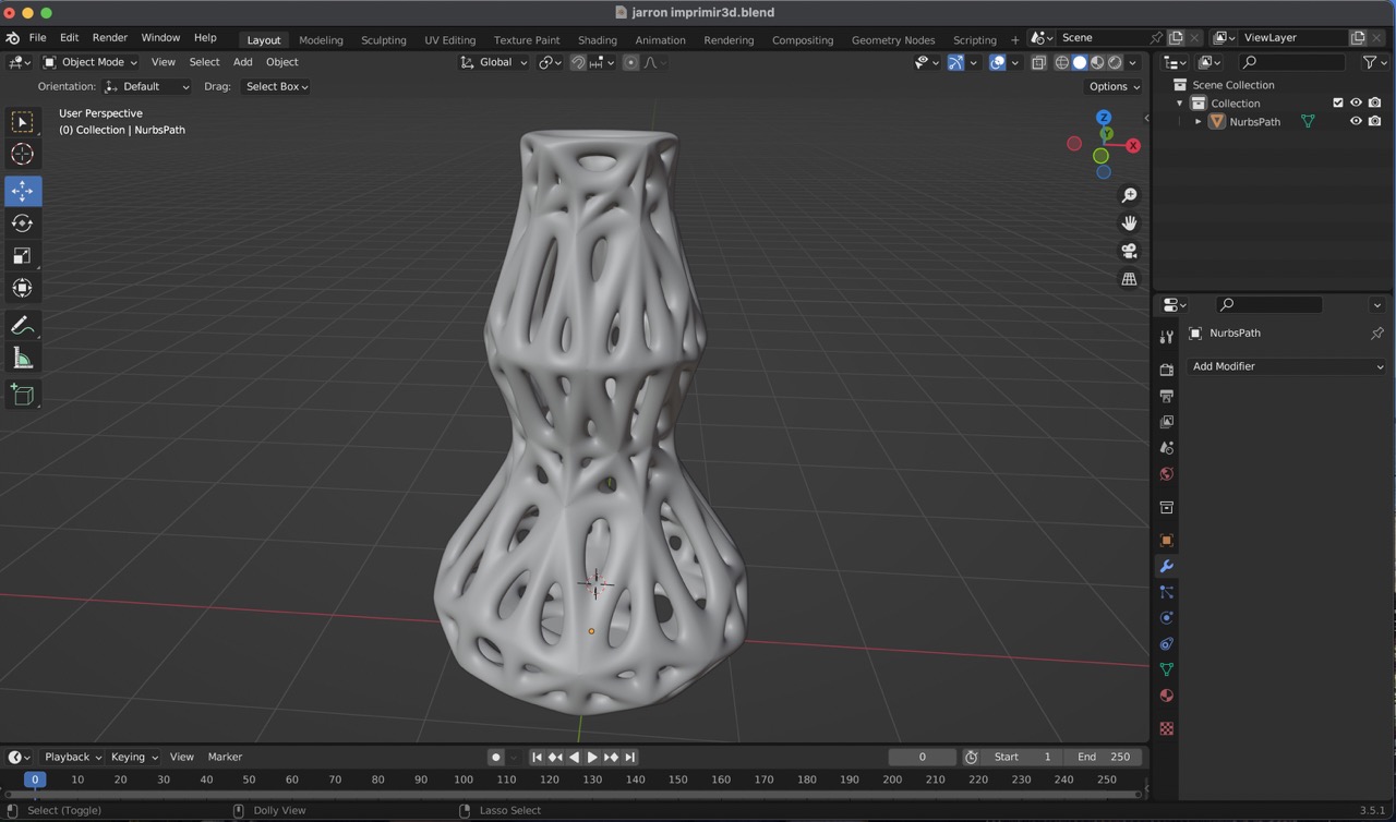
Designing a vase with Blender
This was my first time using Blender, a software I had been curious about for some time. After facing complications with the previous attempts, I decided to give Blender a try for this particular assignment. To create the 3D model, I discovered a tutorial for designing very interesting vases. I began by experimenting with various curves until I achieved a design that appealed to me. Here are the steps I followed to get my final result:
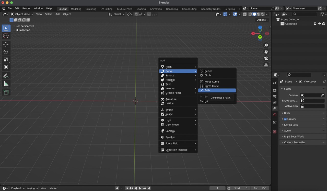
1:
To start creating a path in Blender, begin by accessing the menu with 'Shift A', then select 'Curve', and finally choose 'Path'.
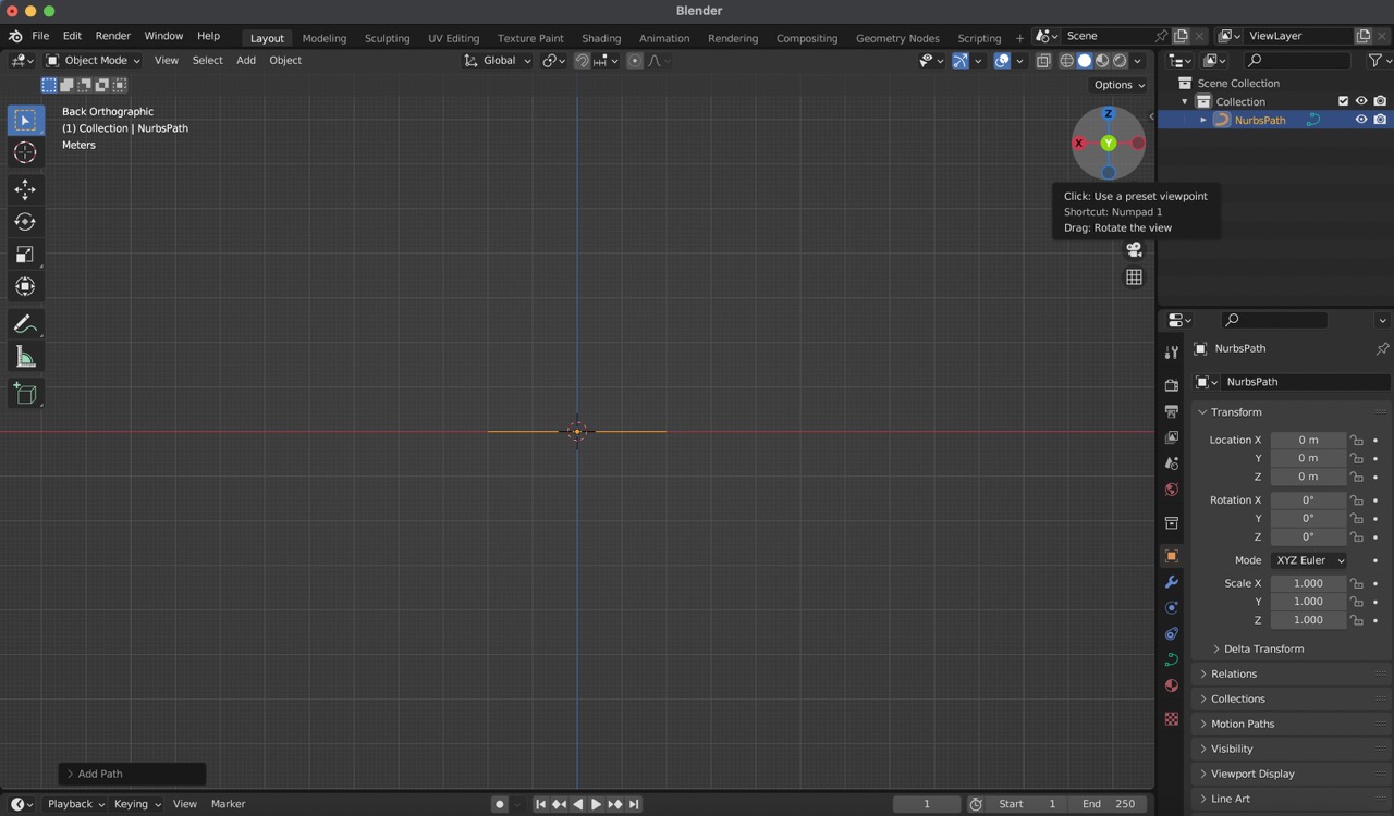
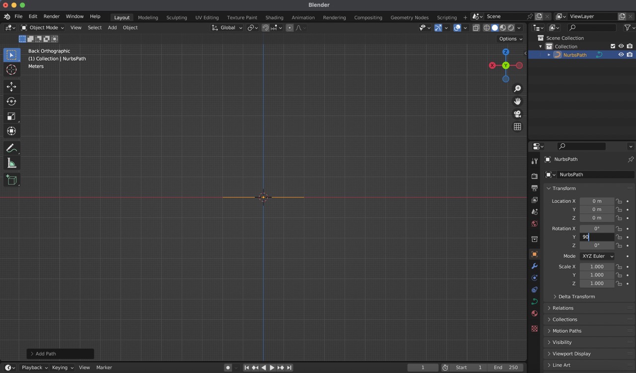
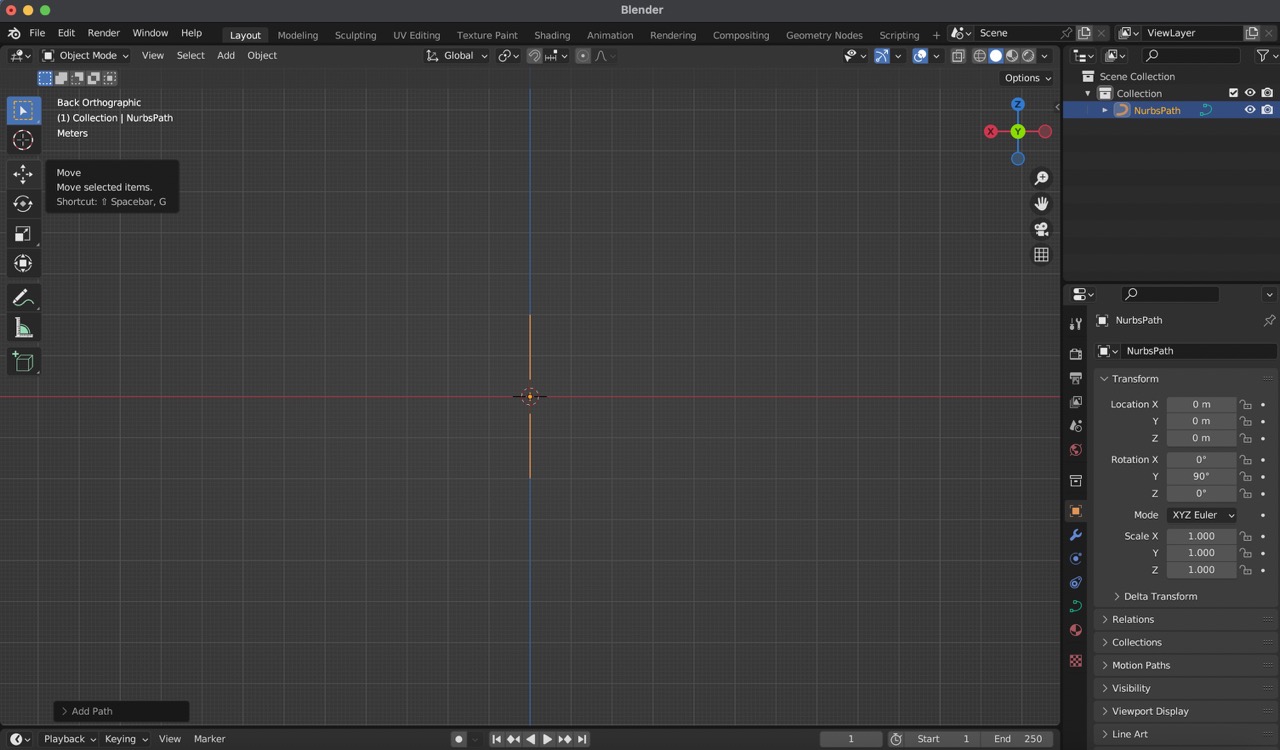
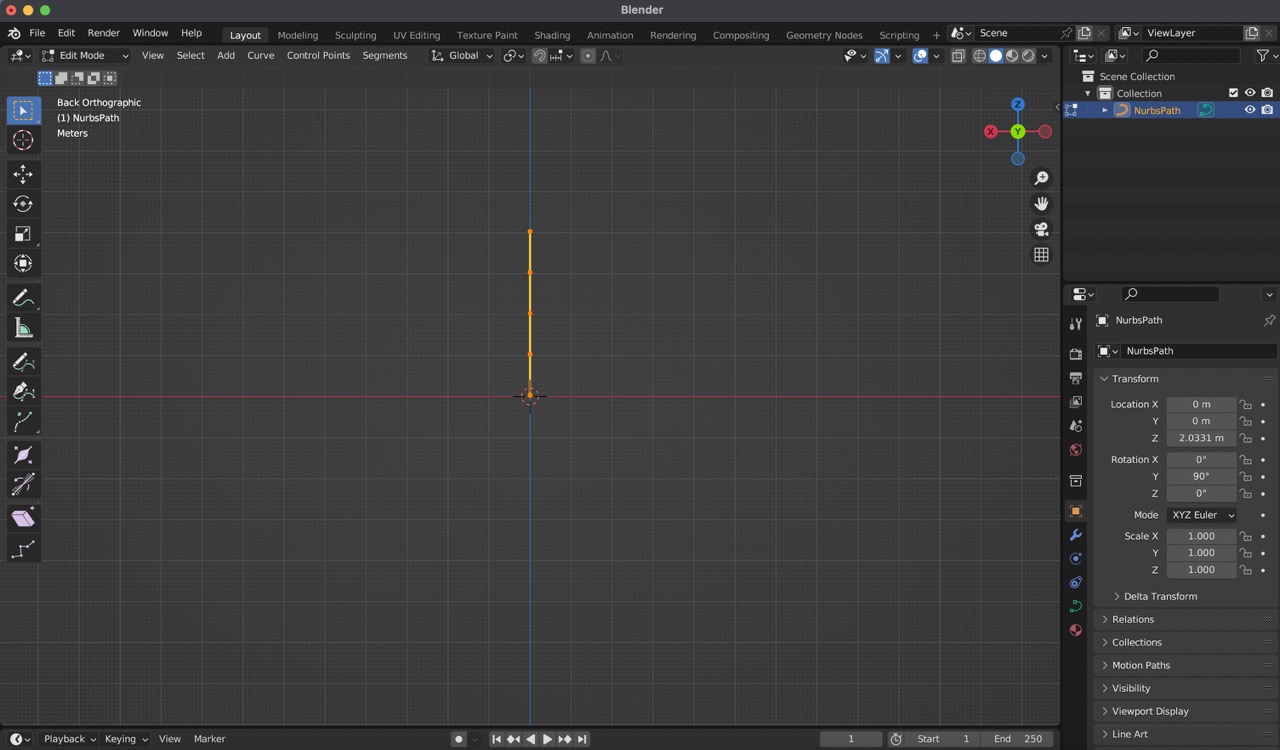
2:
Next, adjust the view by locating the green circle representing the 'Y' axis in the top right corner. On the right-hand side panel, rotate the line you just created to a 90-degree angle on the 'Y' axis.
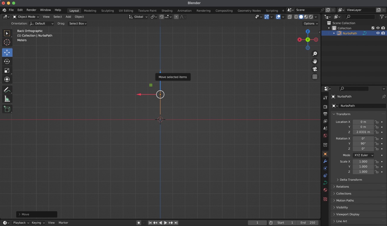
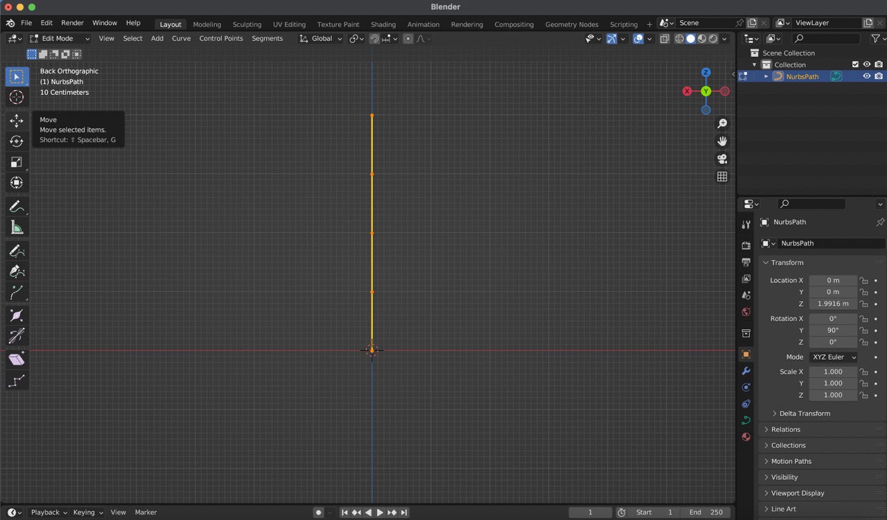
3:
Now, using the move tool found on the left-hand side tool menu, relocate the line so that it sits above the 'X' axis.
4:
Enter edit mode either through the top right menu or by pressing the 'Tab' key.
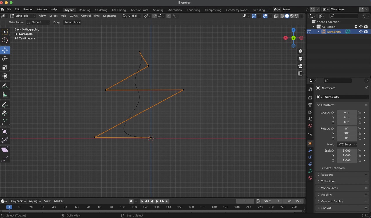
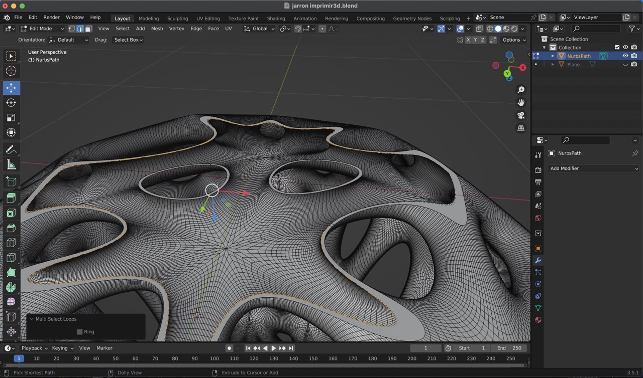
5:
Within edit mode, utilize the move tool once more to adjust each point along the line, shaping it into the desired curve.
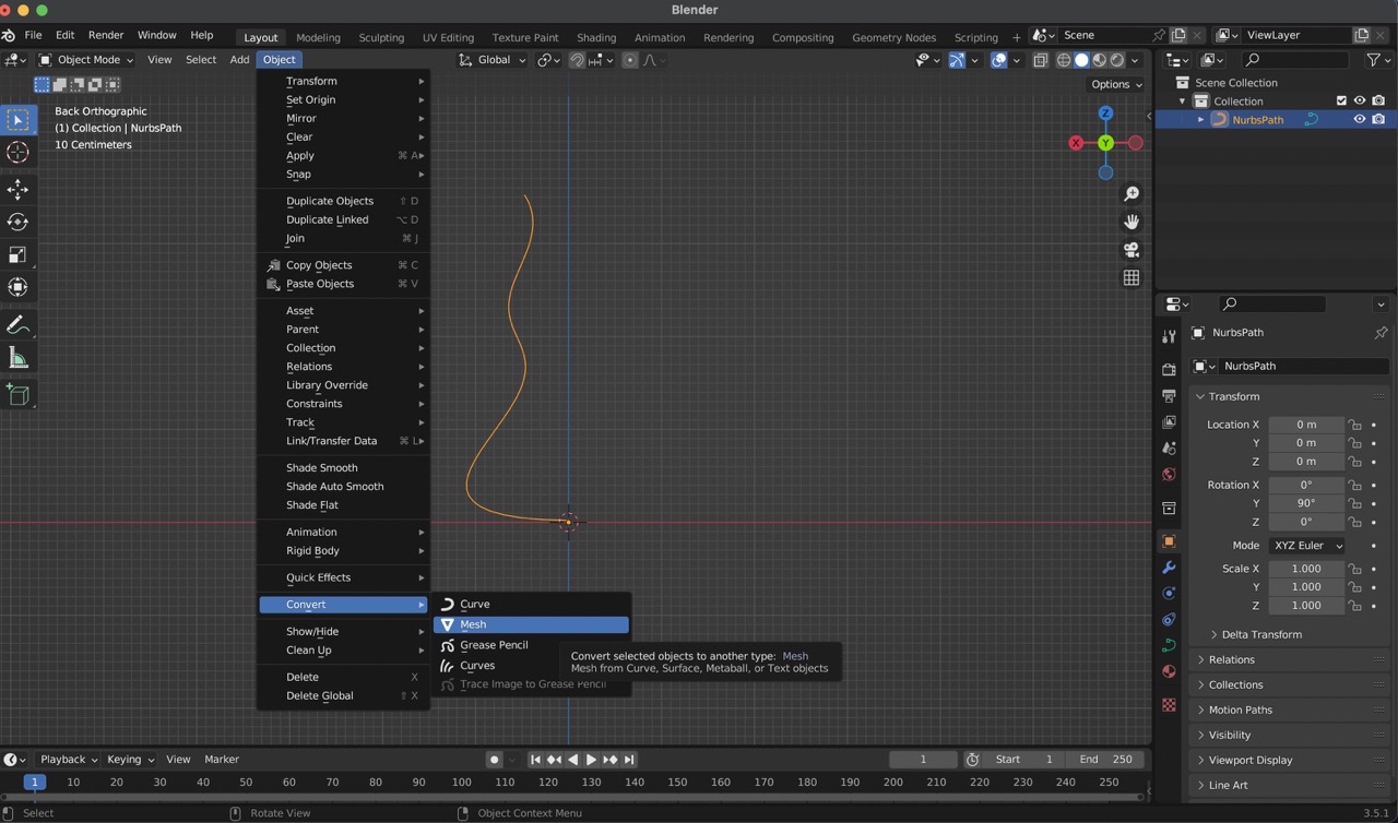
6:
Once satisfied with the curve, convert it to a mesh by navigating to the 'Object' menu, selecting 'Convert', and then clicking on 'Mesh'.
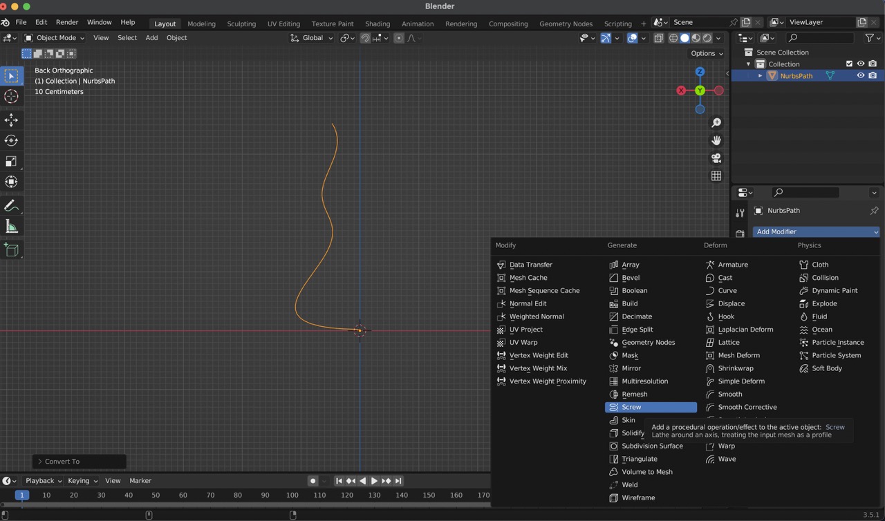
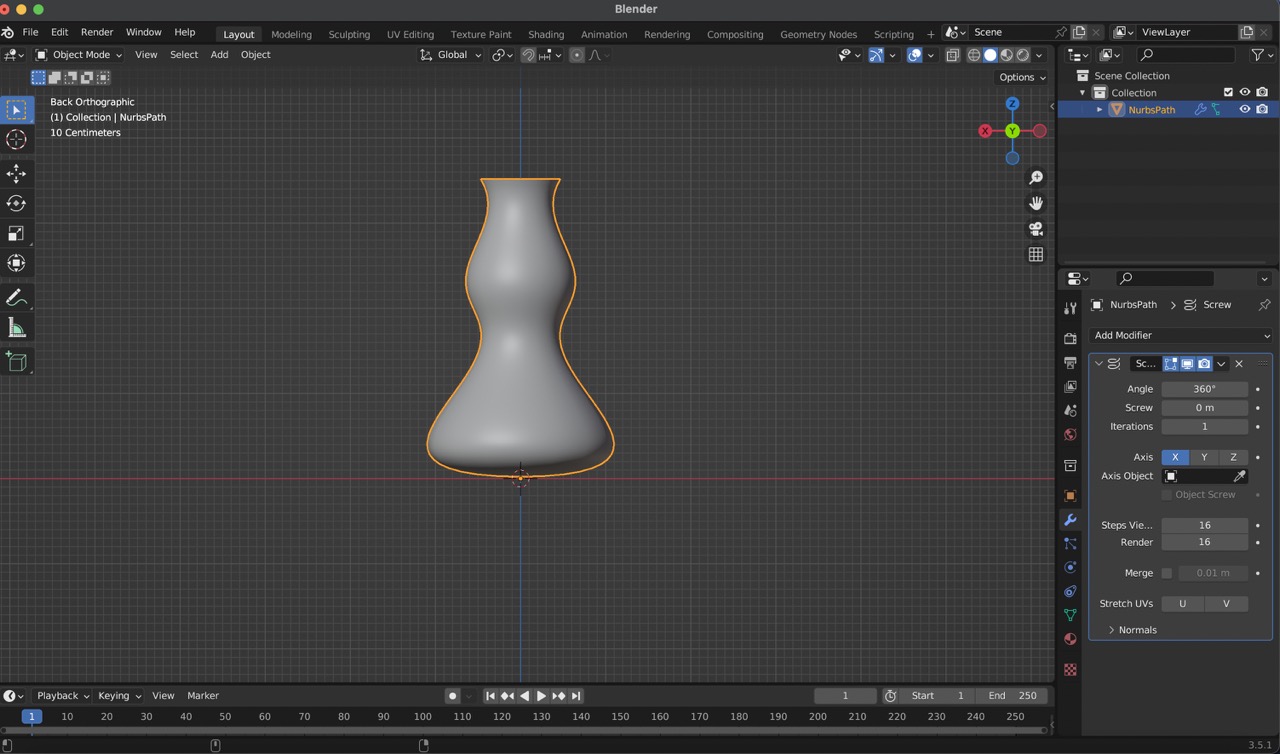
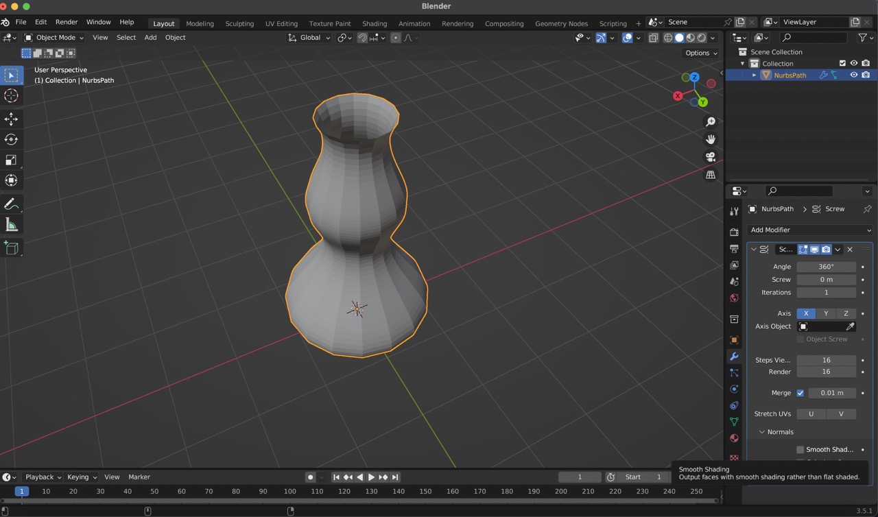
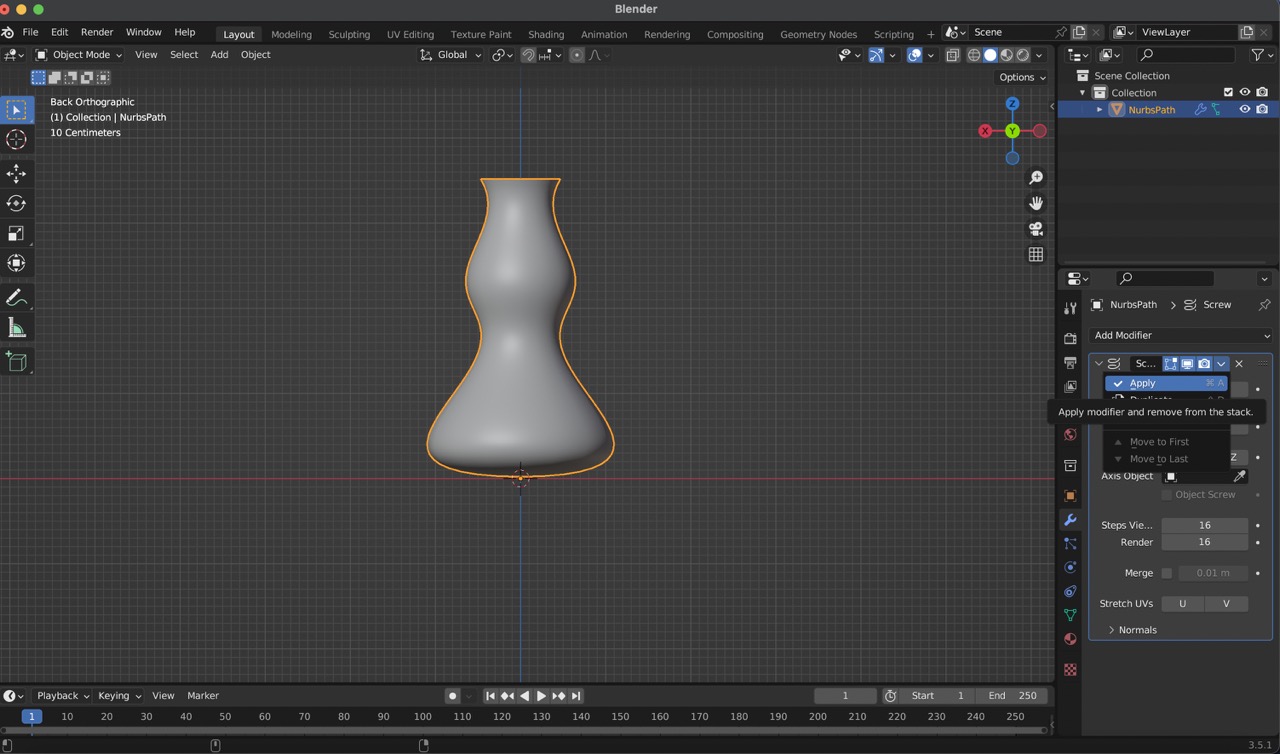
7:
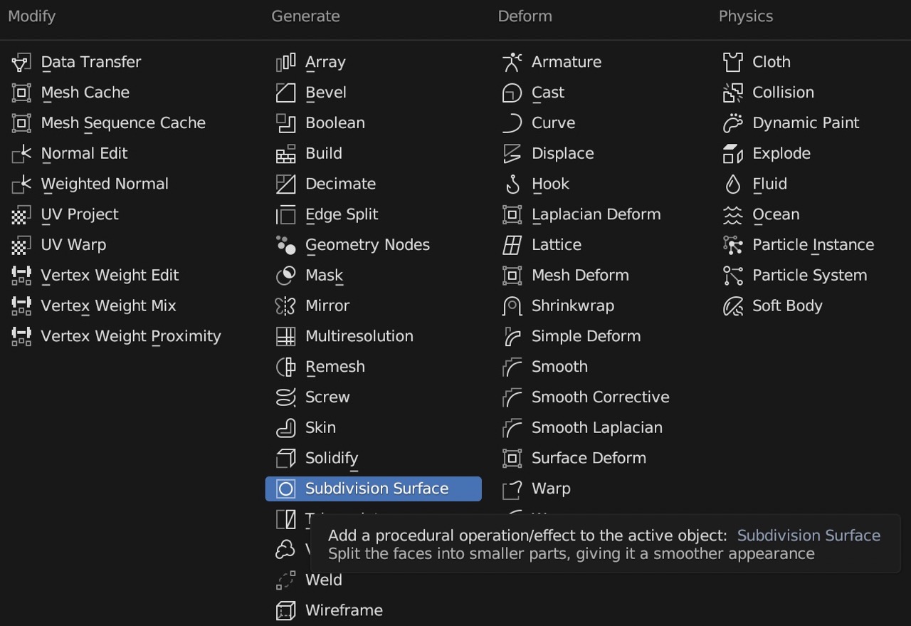
Now, proceed to add modifiers by accessing the 'Add Modifier' menu. Choose 'Screw', adjusting the axis to 'X', and enabling 'Merge' while disabling 'Smooth Shading'. Once you have changed these settings, click on ‘Apply’.
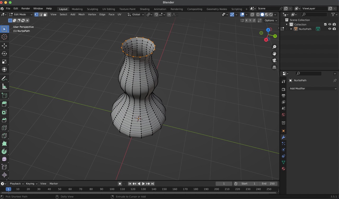
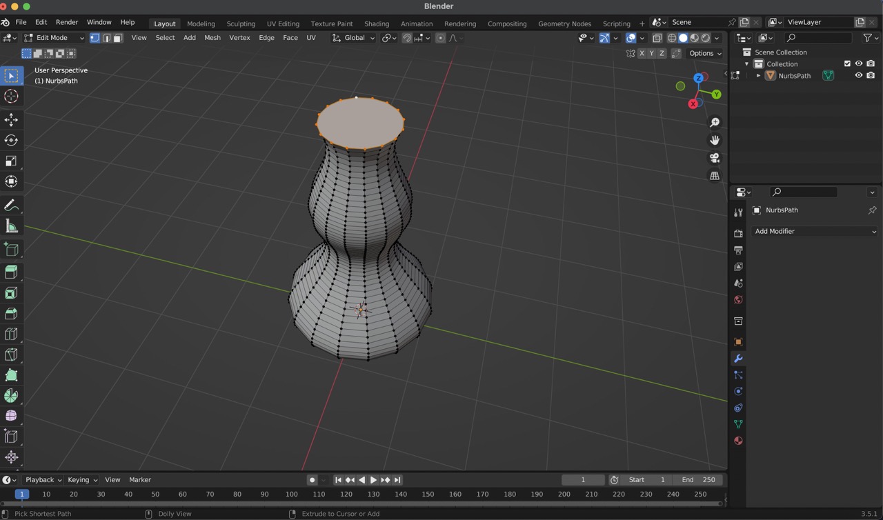
8:
Returning to edit mode ('Tab' key), use the 'Option Shift' command to select all points in a row, then press 'F' to fill in the outline.
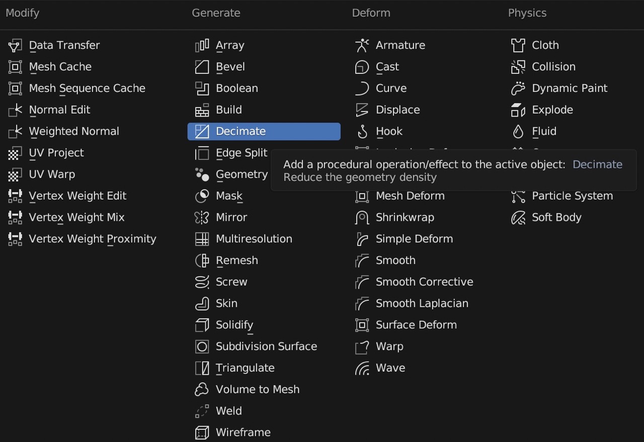
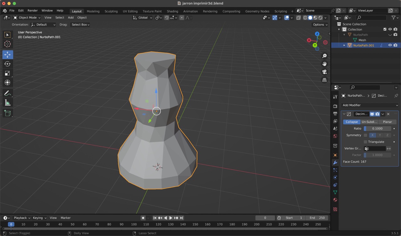
9:
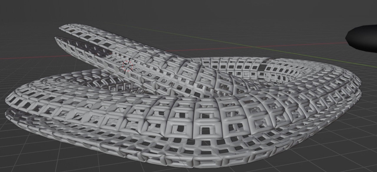
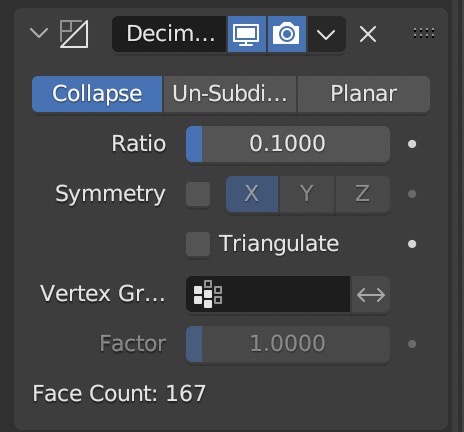
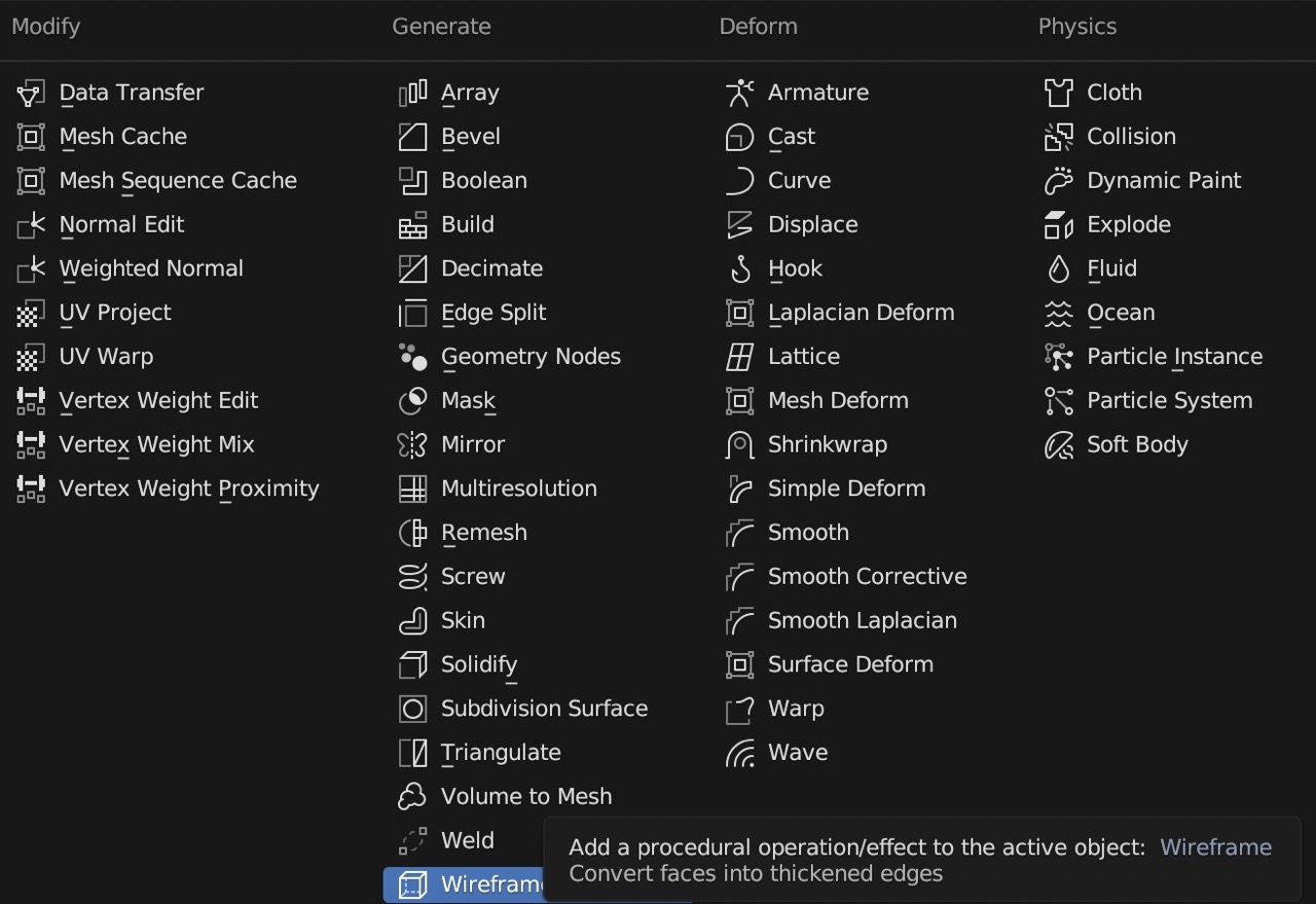
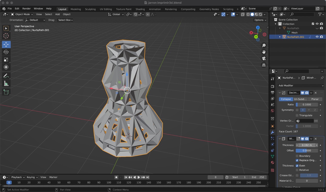
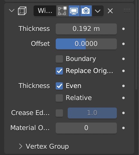
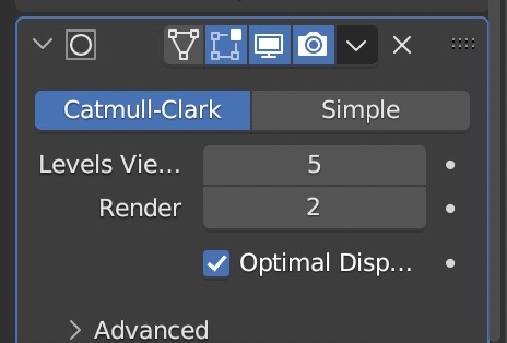
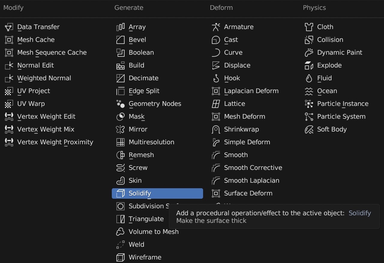
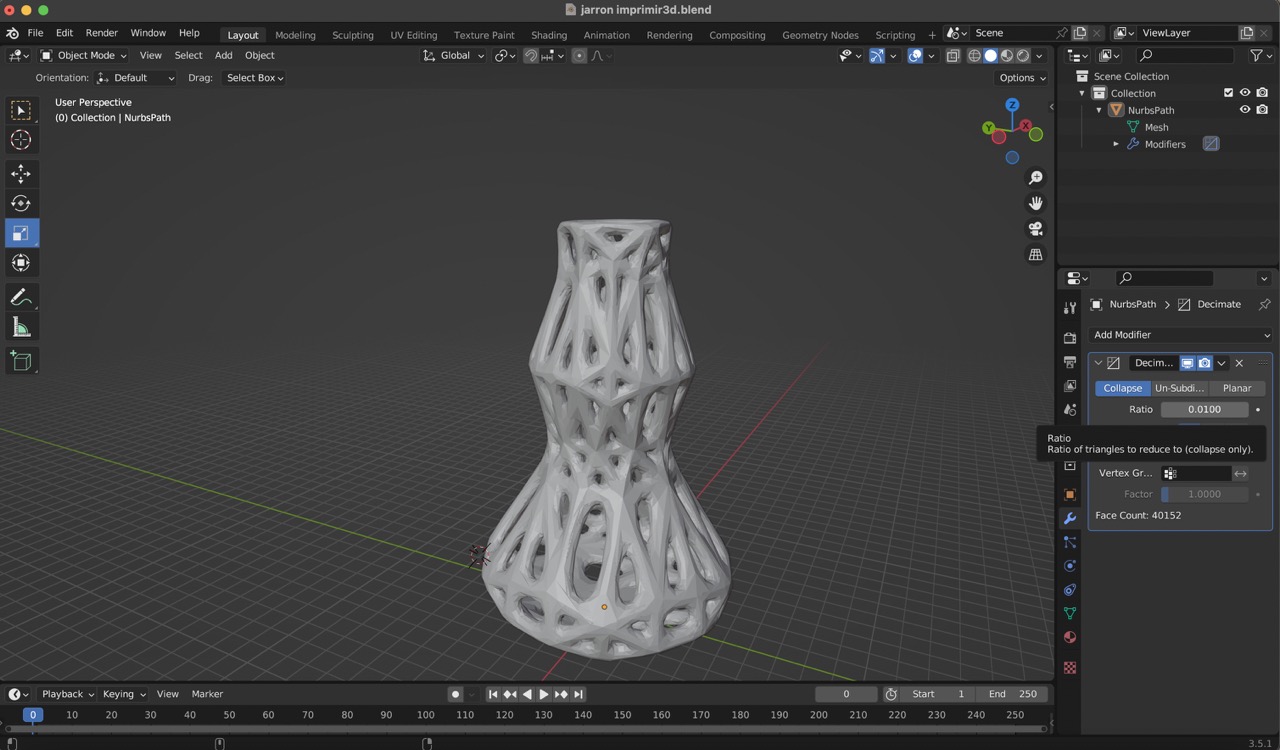
To further enhance the design, experiment with additional modifiers. In my case, I utilized the following parameters: 'Decimate' with a ratio of 0.1, 'Wireframe' with a thickness of 0.192, 'Subdivision Surface' set to 5 levels, and 'Solidify' with a thickness of 0.01.
Decimate
Wireframe
Subidvision Surface
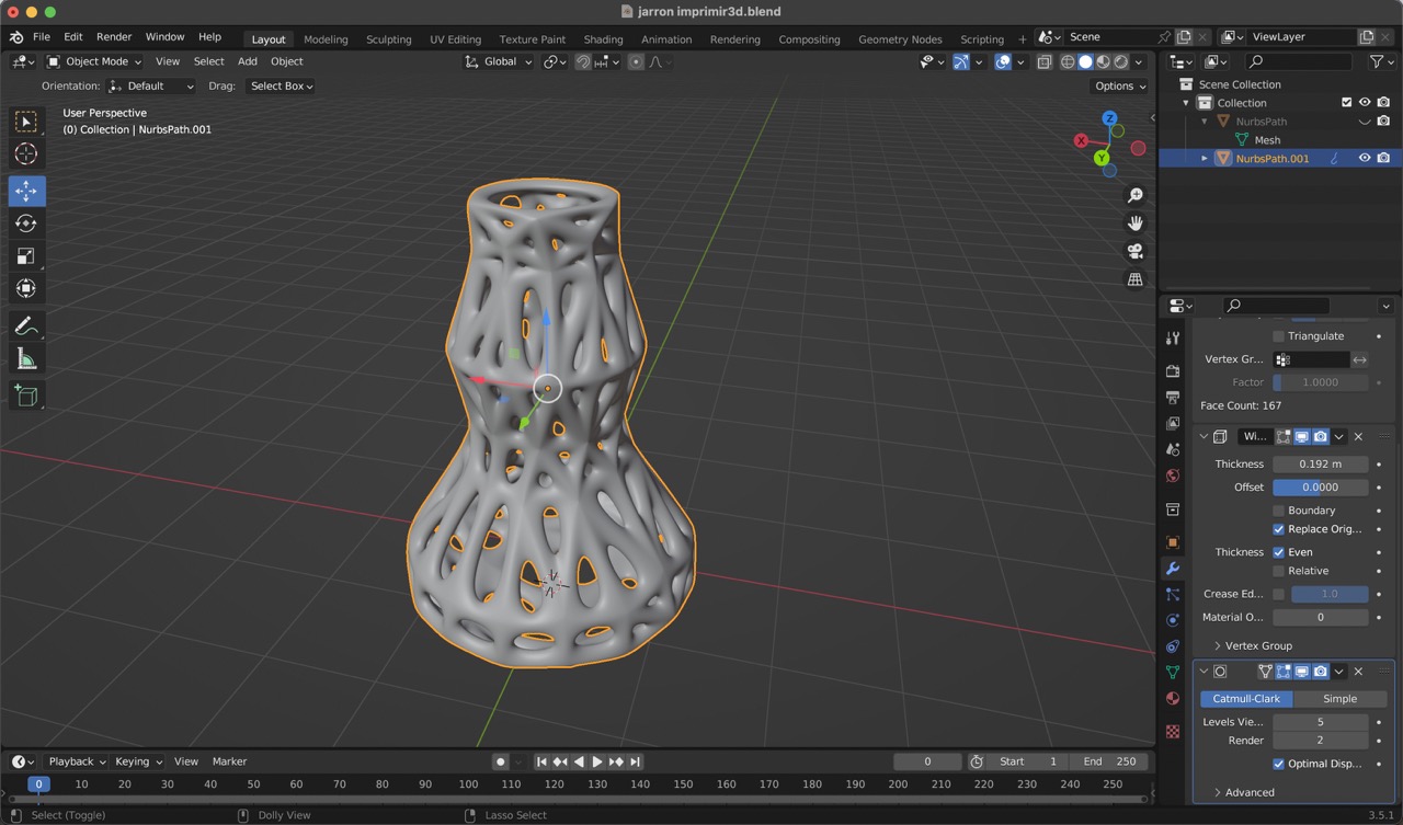
Solidify
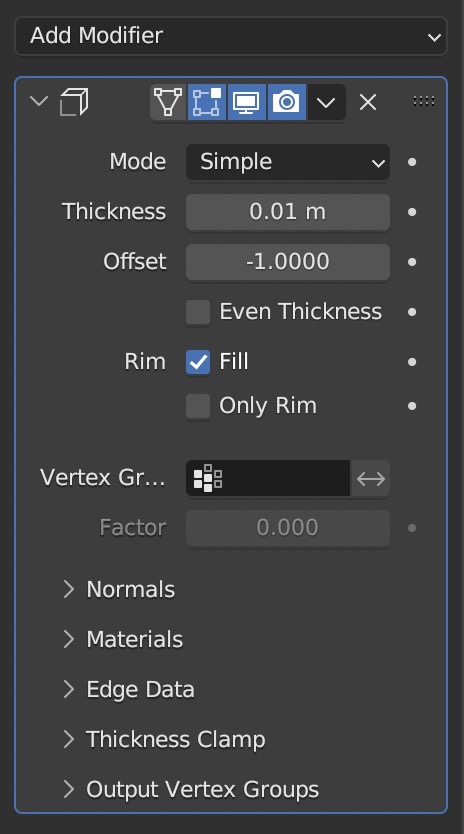
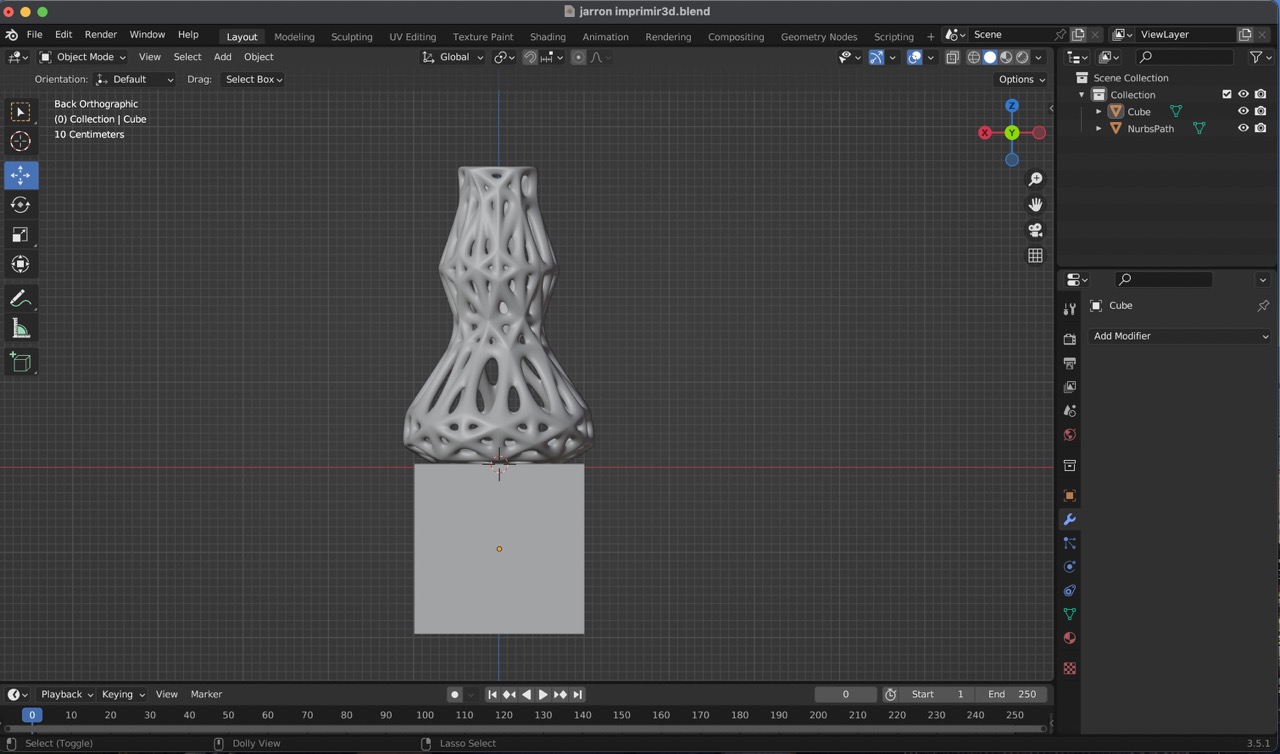
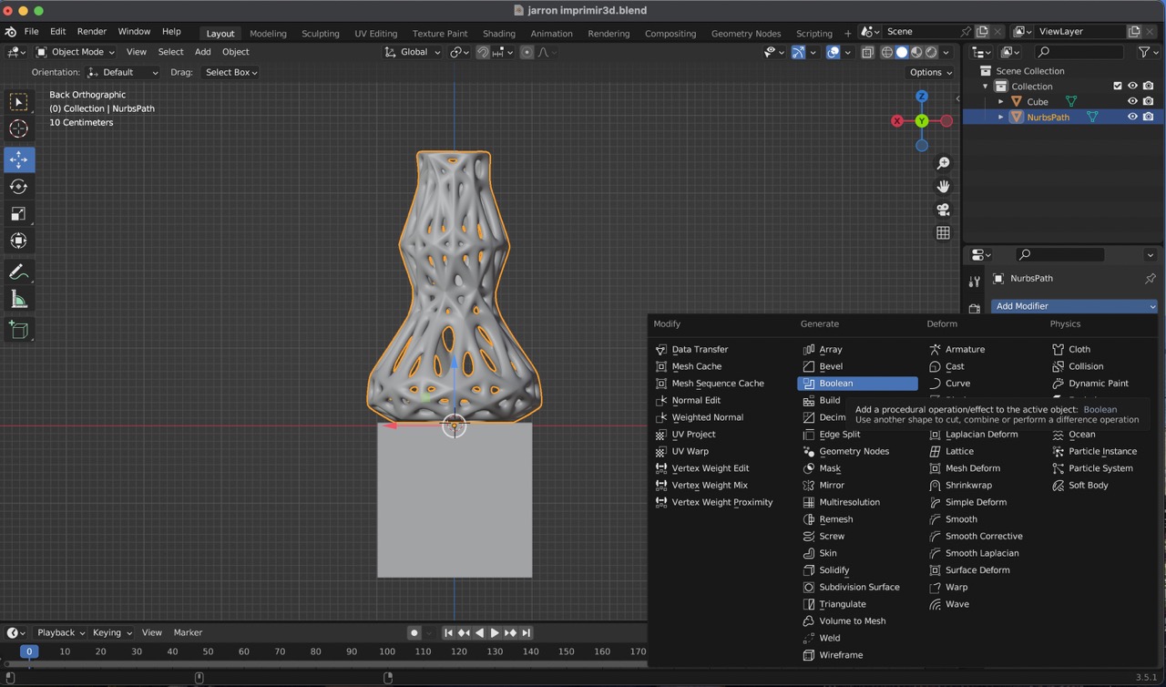
10:
After completing the vase, I noticed an issue with the base being curved rather than flat, posing a challenge for 3D printing. To fix this, I used a boolean difference. I began by creating a square mesh from the 'Add' menu under 'Mesh' and selecting 'Cube'. Subsequently, I added a 'Boolean' modifier.
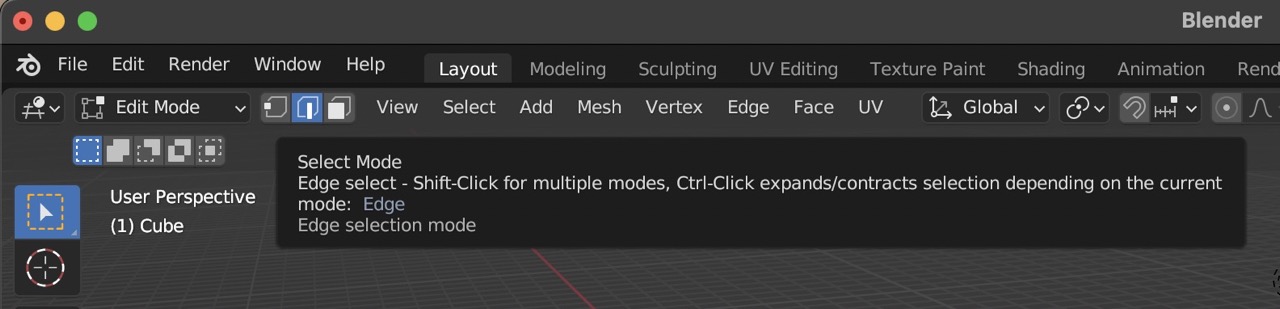
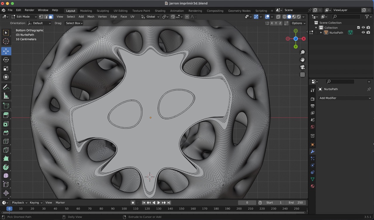
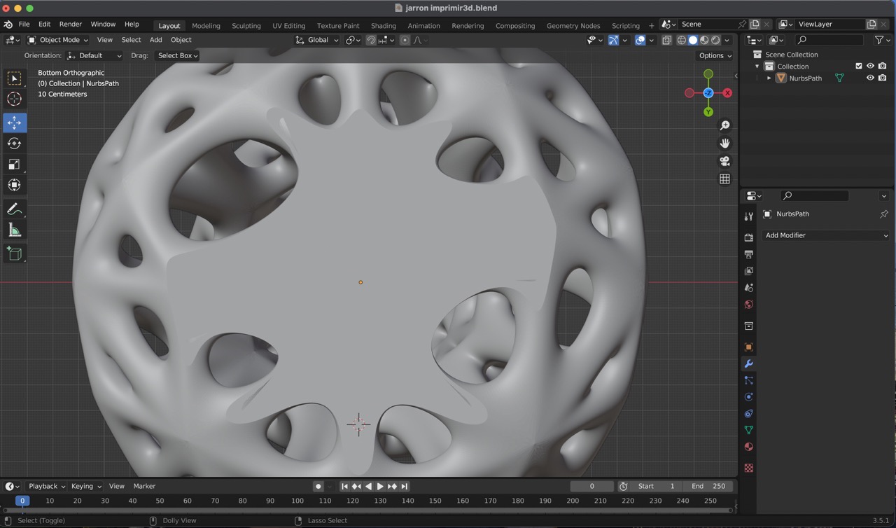
11:
However, this process resulted in the mesh on the base having a hole. To resolve this, I re-entered edit mode and adjusted the 'Select Mode' to 'Edges'. I then selected all the edges from the base that were affected by the boolean operation and filled them in using the 'F' key. This corrected the issue and ensured a solid base suitable for 3D printing..
Ready to 3D print!
1. Export your file
Start by exporting your 3D model in the STL format. This is the standard file type used for 3D printing.
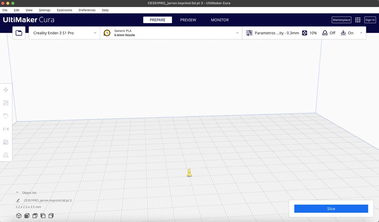
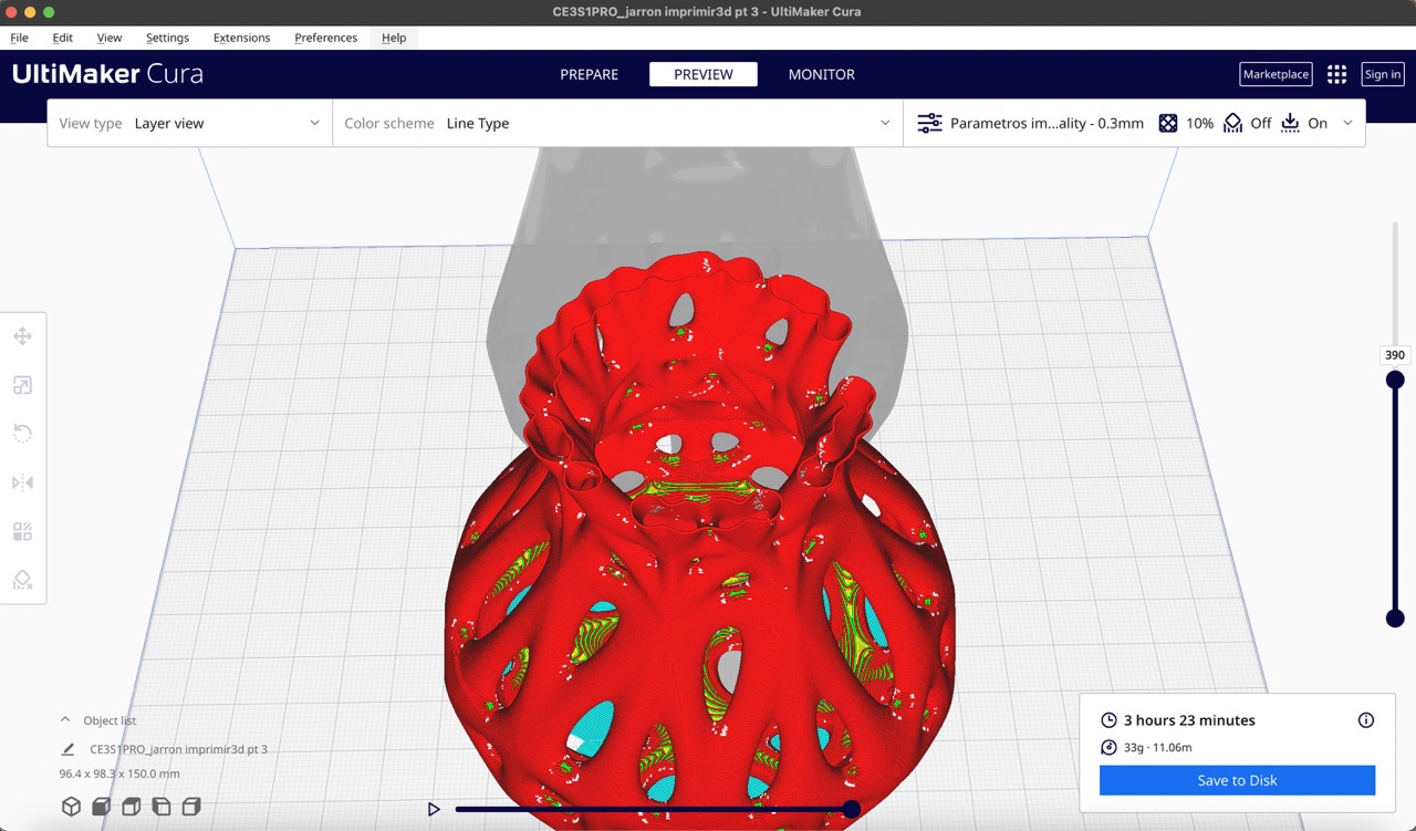
2. Prepare your file for printing
To prepare a file you can use different softwares, in my case I used UltiMaker Cura.
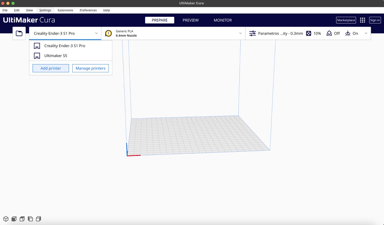
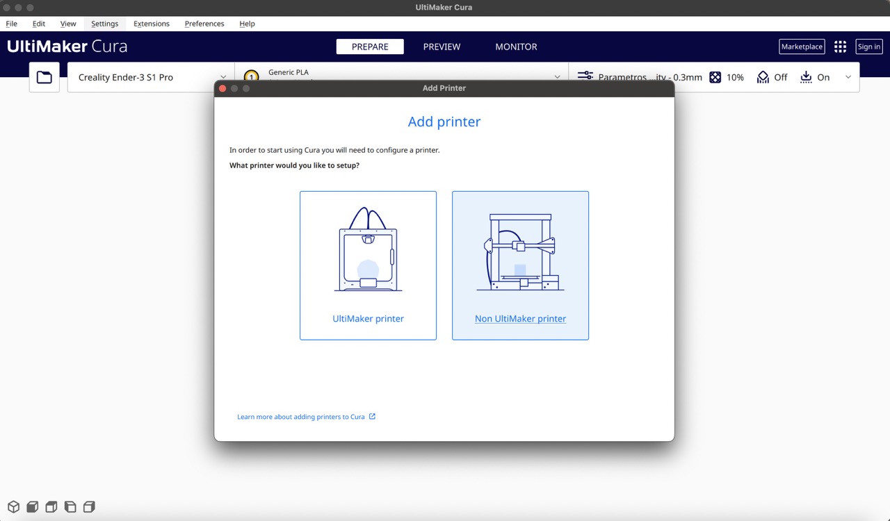
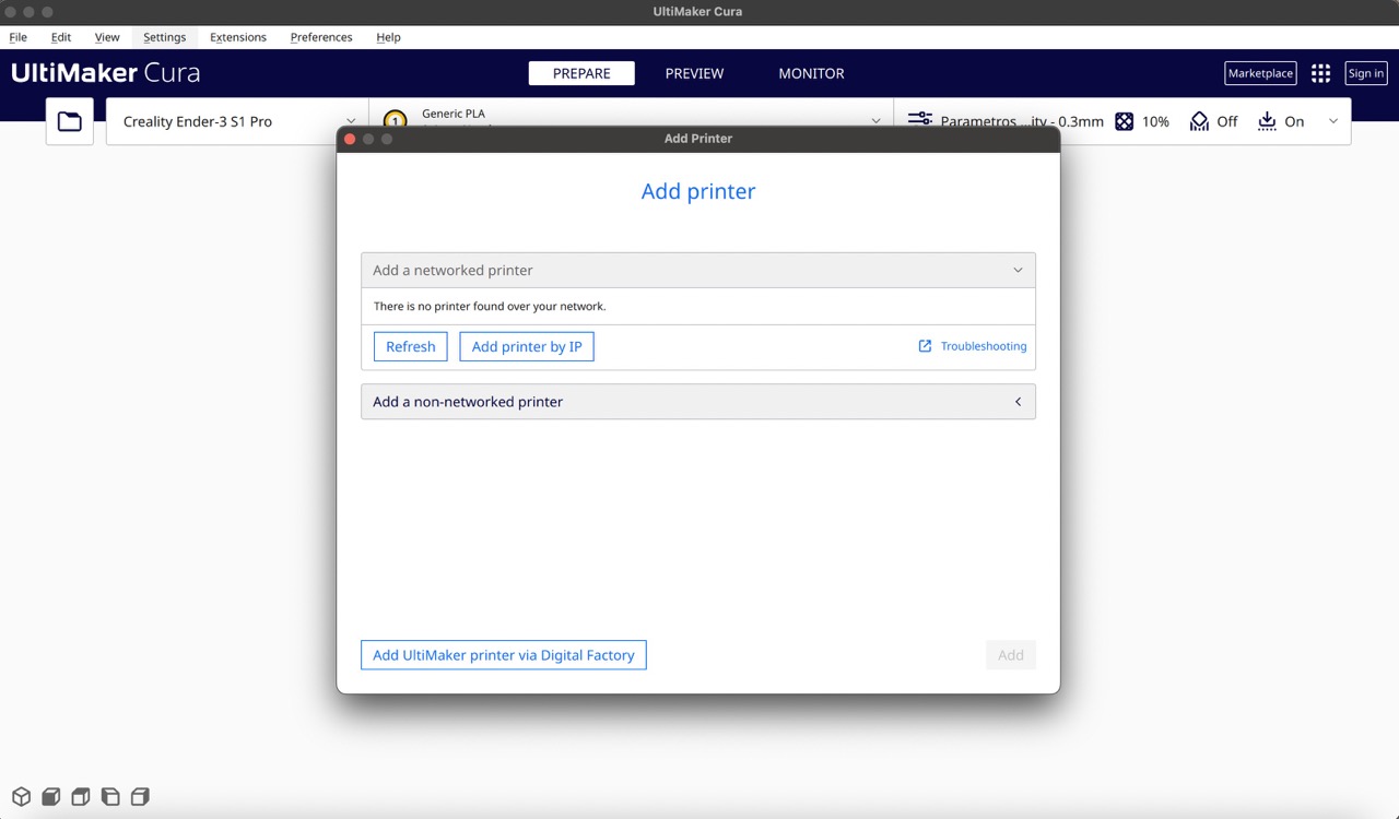
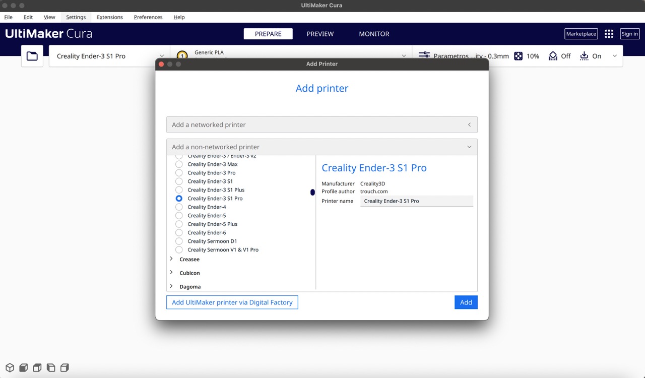
3. Select printer
In UltiMaker Cura add your printer make sure it is the correct model, for example, I used a Creality Ender 3 S1 Pro.
4. Import your file
In UltiMaker Cura add your printer make sure it is the correct model, for example, I used a Creality Ender 3 S1 Pro.
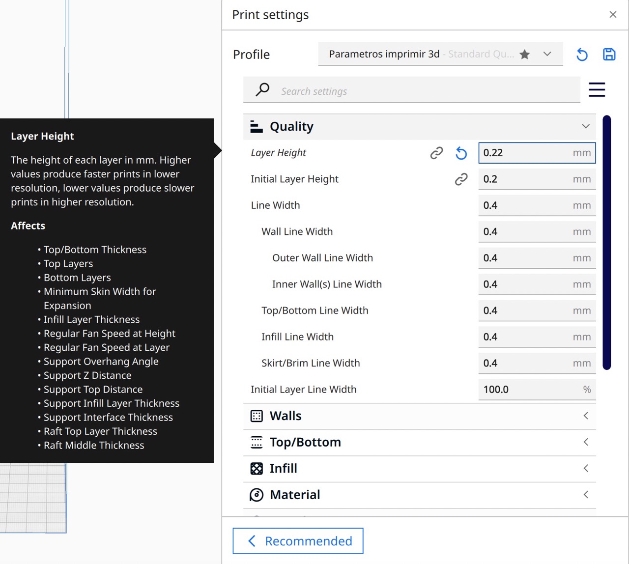
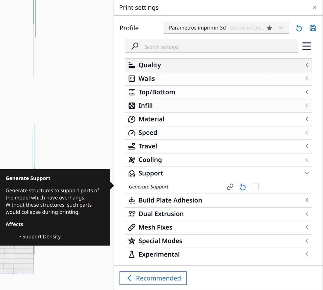
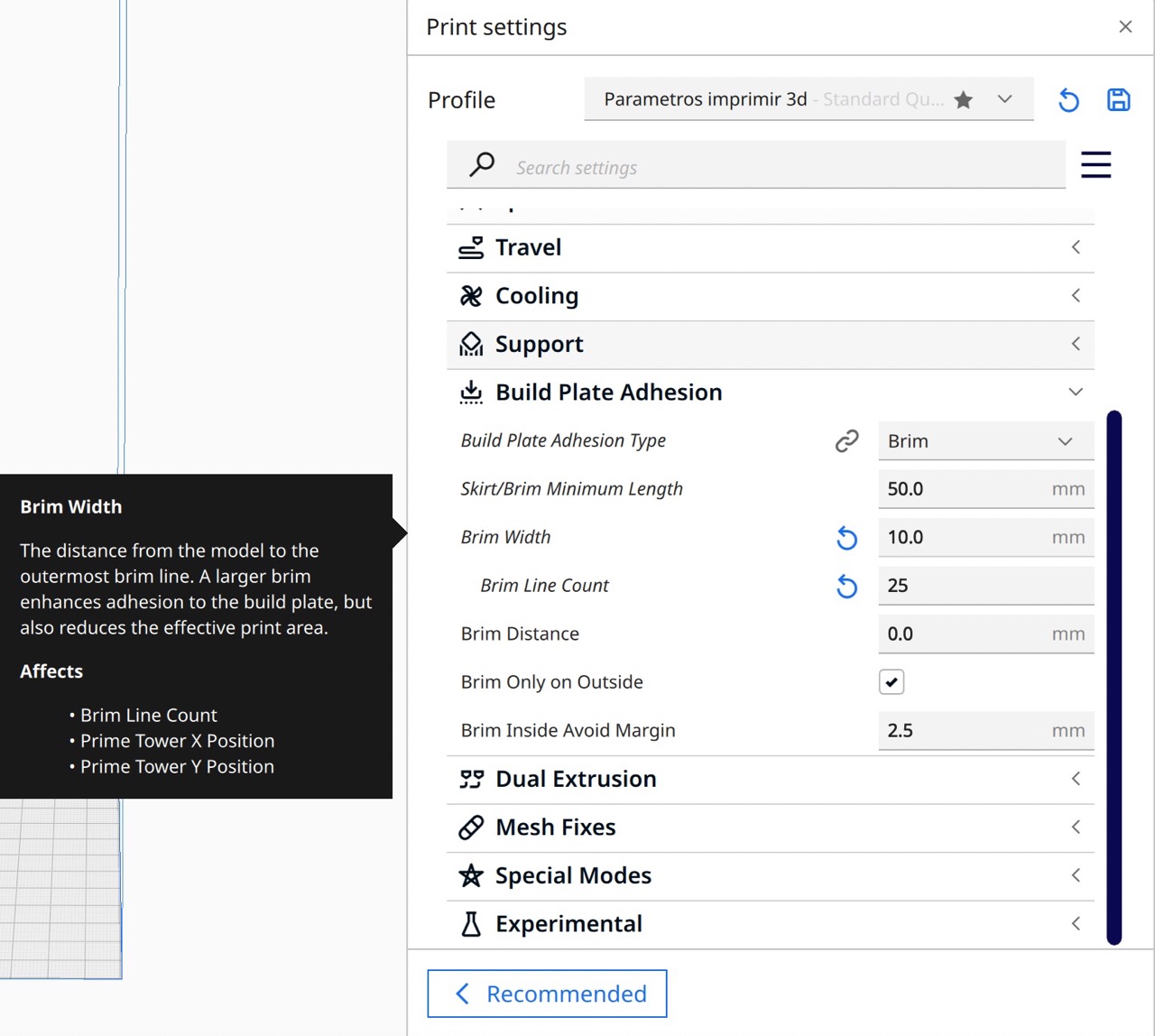
5. Adjust settings
You can customize each parameter based on your printing needs. Here are the settings I used:
- Quality: Layer Height: 0.22mm (Higher values result in higher resolution but longer print times)
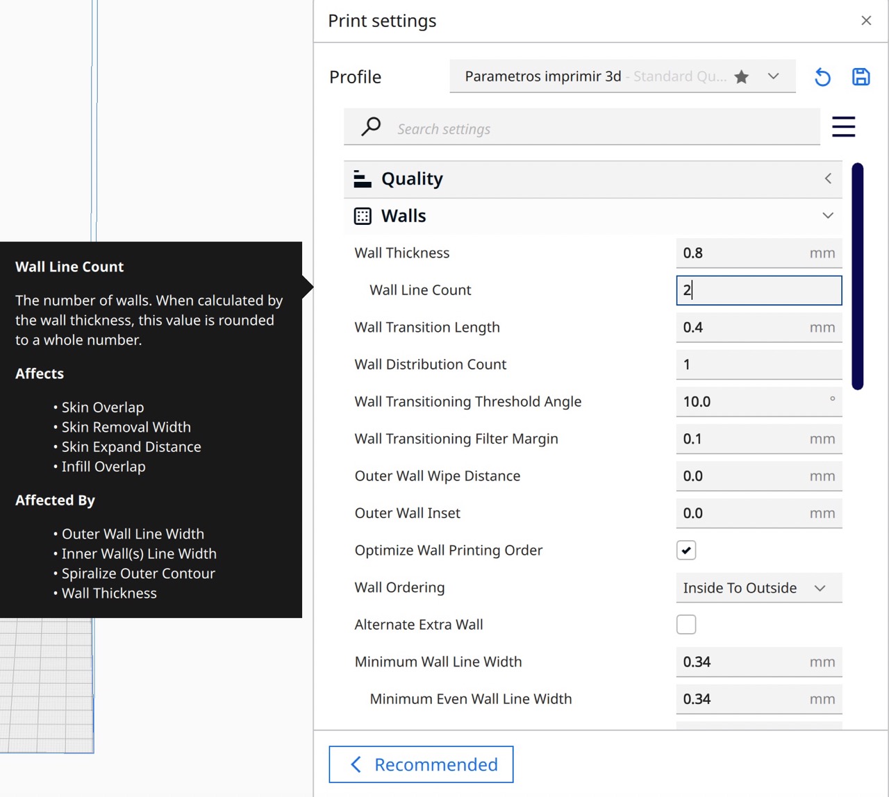
- Walls: Wall Line Count: 2
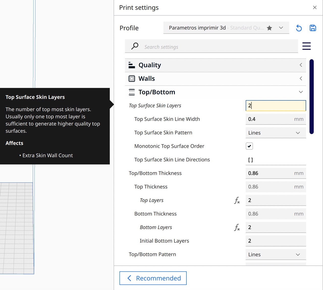
- Top/Bottom: Top surface skin layers: 2
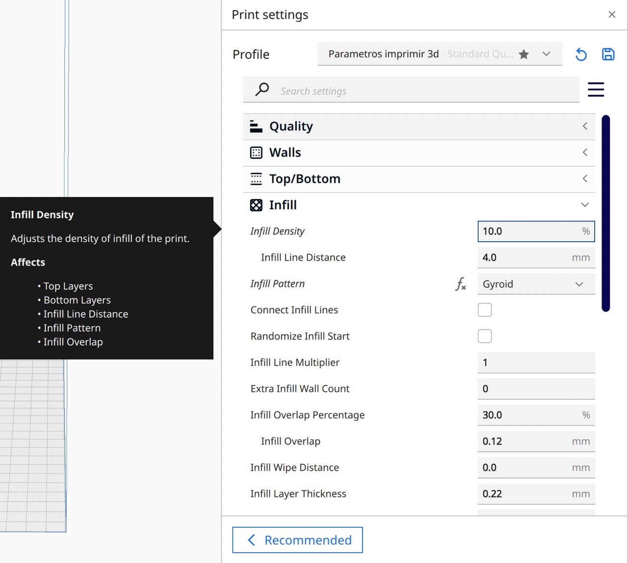
- Infill: Infill density: 10%. Infill pattern: Gyroid
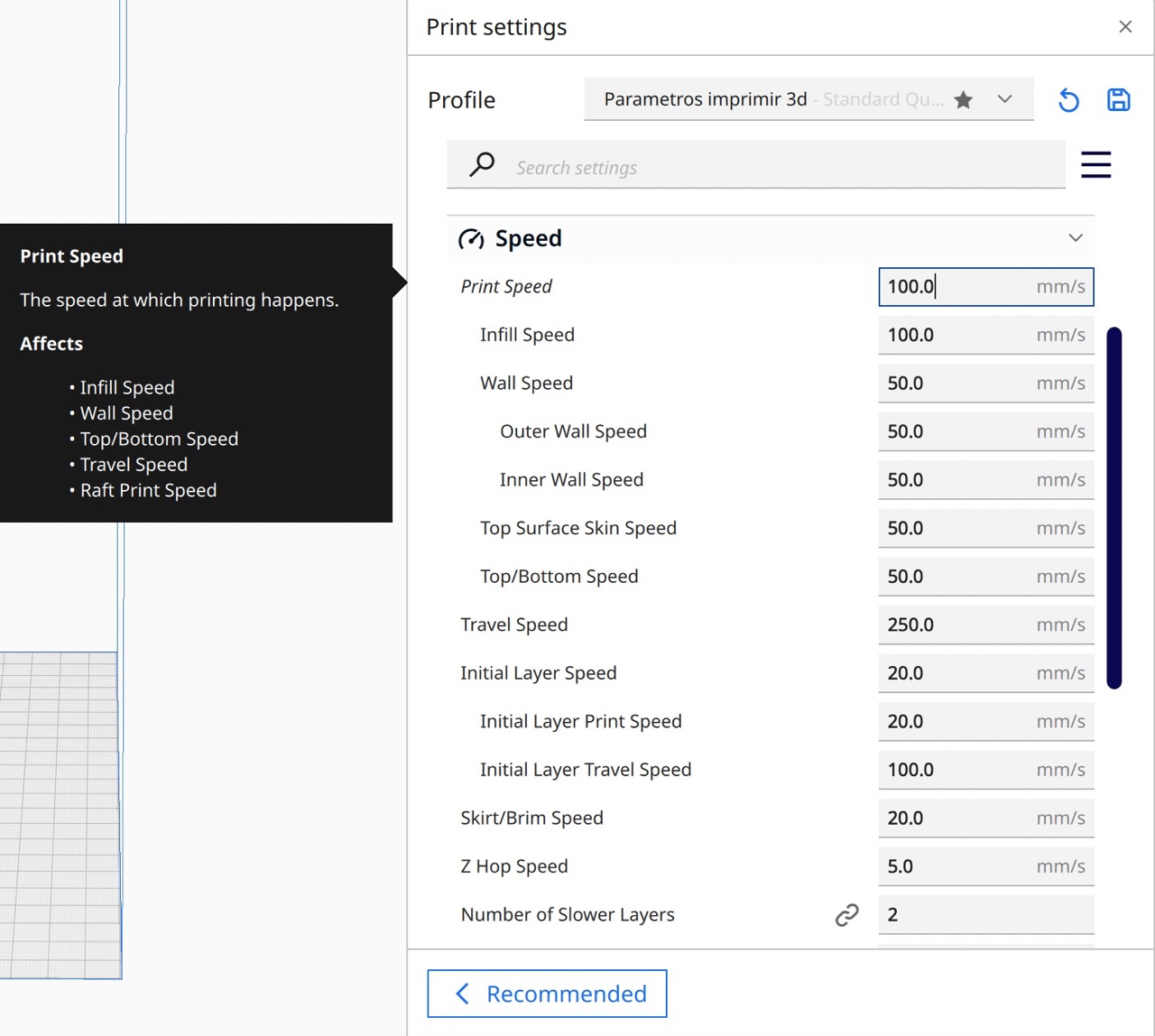
- Speed: Print speed: 100 mm/s
- Support: You can turn this on to create supports for your geometry, I didnt turn it on because the print time increased significantly.
- Build plate adhesion: Build plate adhesion type: Brim. Brim minimum length: 50 mm. Brim width: 10 mm. Brim line count: 25 mm
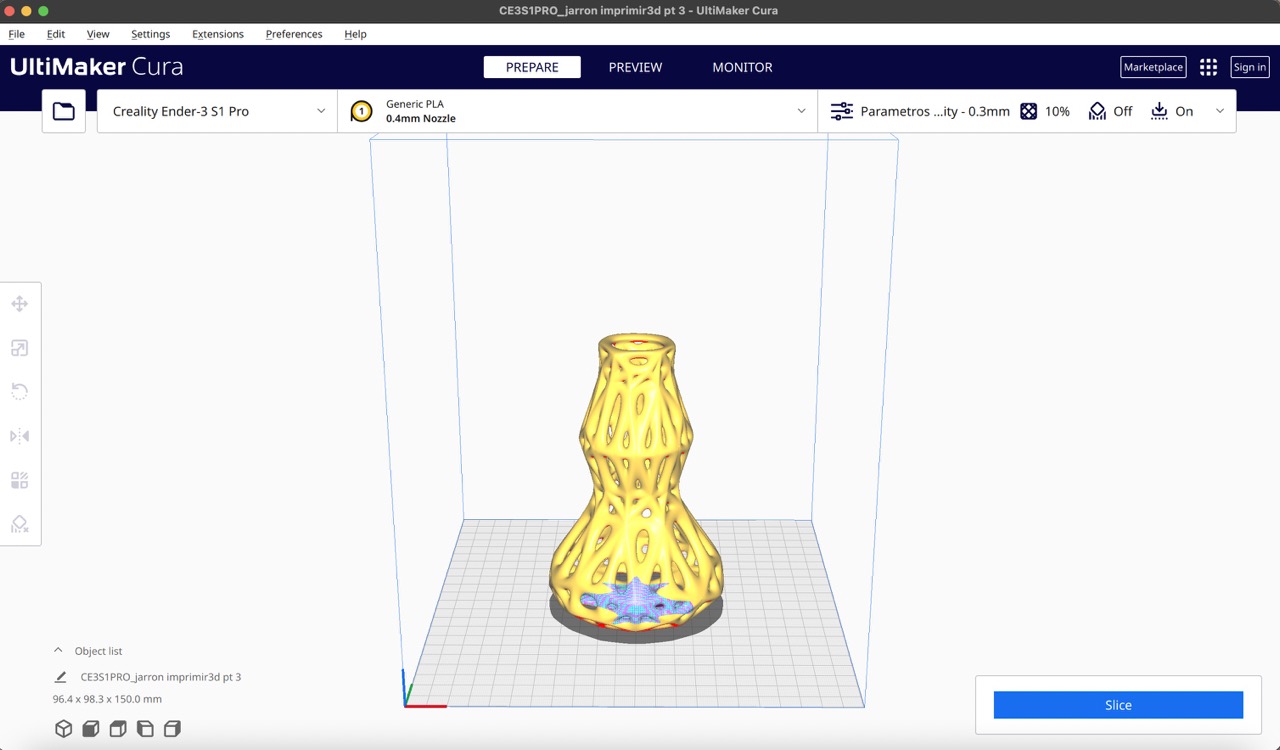
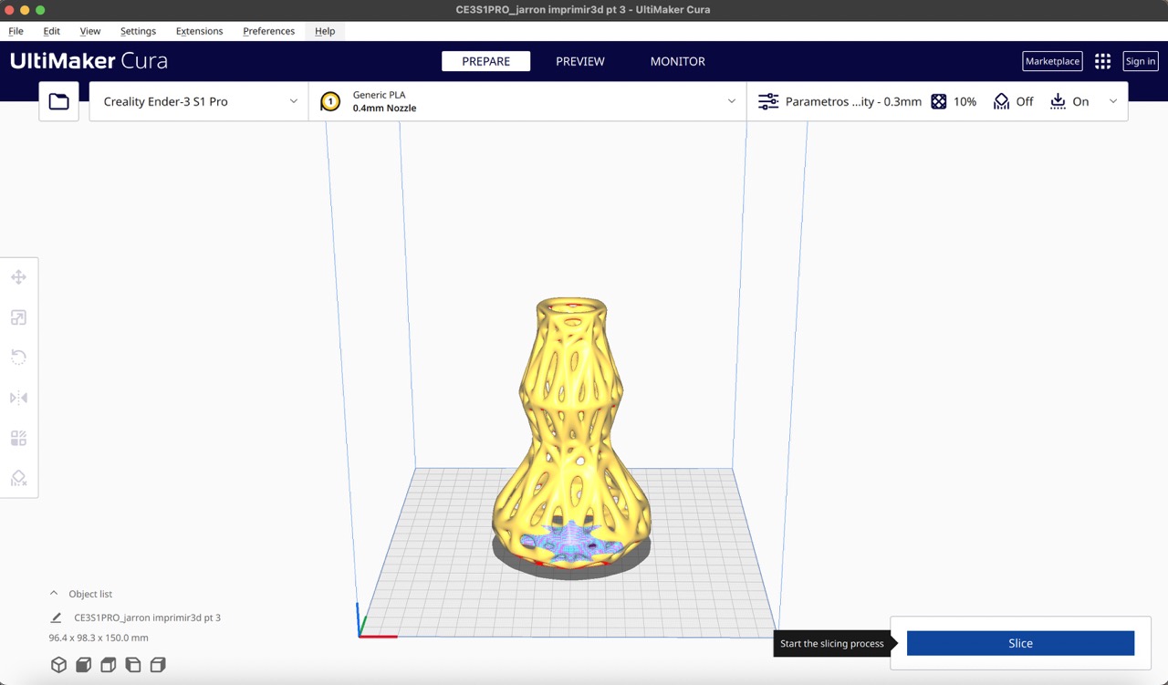
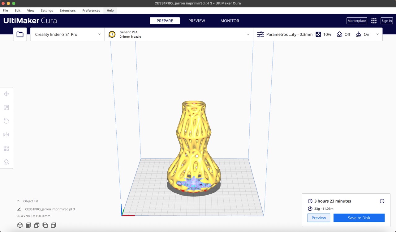
6. Preview and save
To visualize your print by clicking on the 'Slice' button and click on 'Preview', with the slider in the right make sure each printing layer looks good. Once satisfied, save the file as a Gcode.
7. Transfer to printer
Transfer the Gcode file to an SD card and insert it into your 3D printer.
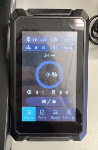
8. Let's print!
Start the printer and heat up the printing bed and nozzle. Recommended temperatures are 200°C for the nozzle and 75°C for the printing bed. Once heated, start the print and observe the initial layers closely for any errors or issues.
Printing time lapse :)
Photos
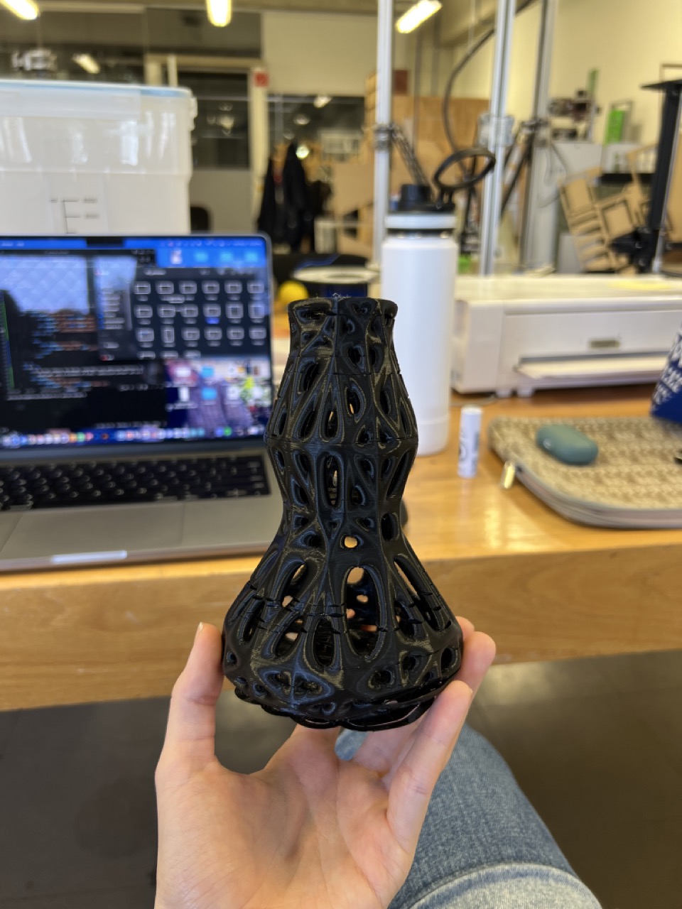
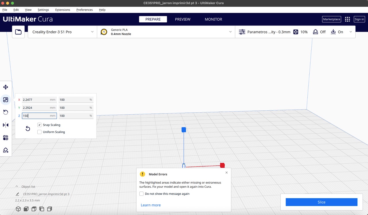
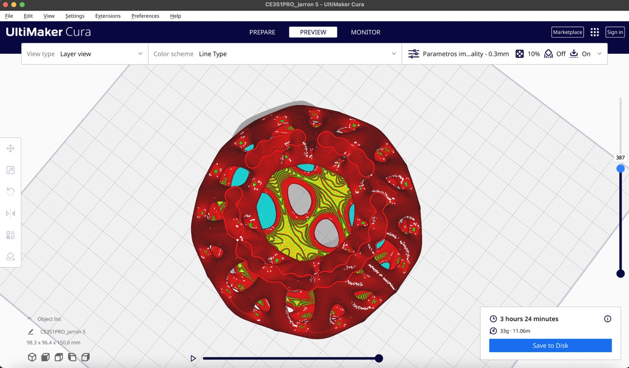
Ups! There is something wrong
As it was my first time using Blender, a mesh-based software, I discovered after printing the vase that it wasn't solid, and thus the gyroid texture wasn't applied as intended. This resulted in small holes in some areas. Despite applying a solidify modifier with a thickness of 0.01, the mesh wasn't completely filled. To address this, I returned to Blender and added another modifier called 'Remesh', setting a thickness of 0.01. After verifying the success of this modification, I imported the new STL file into Ultimaker Cura and confirmed in the preview that the gyroid texture was now properly applied.
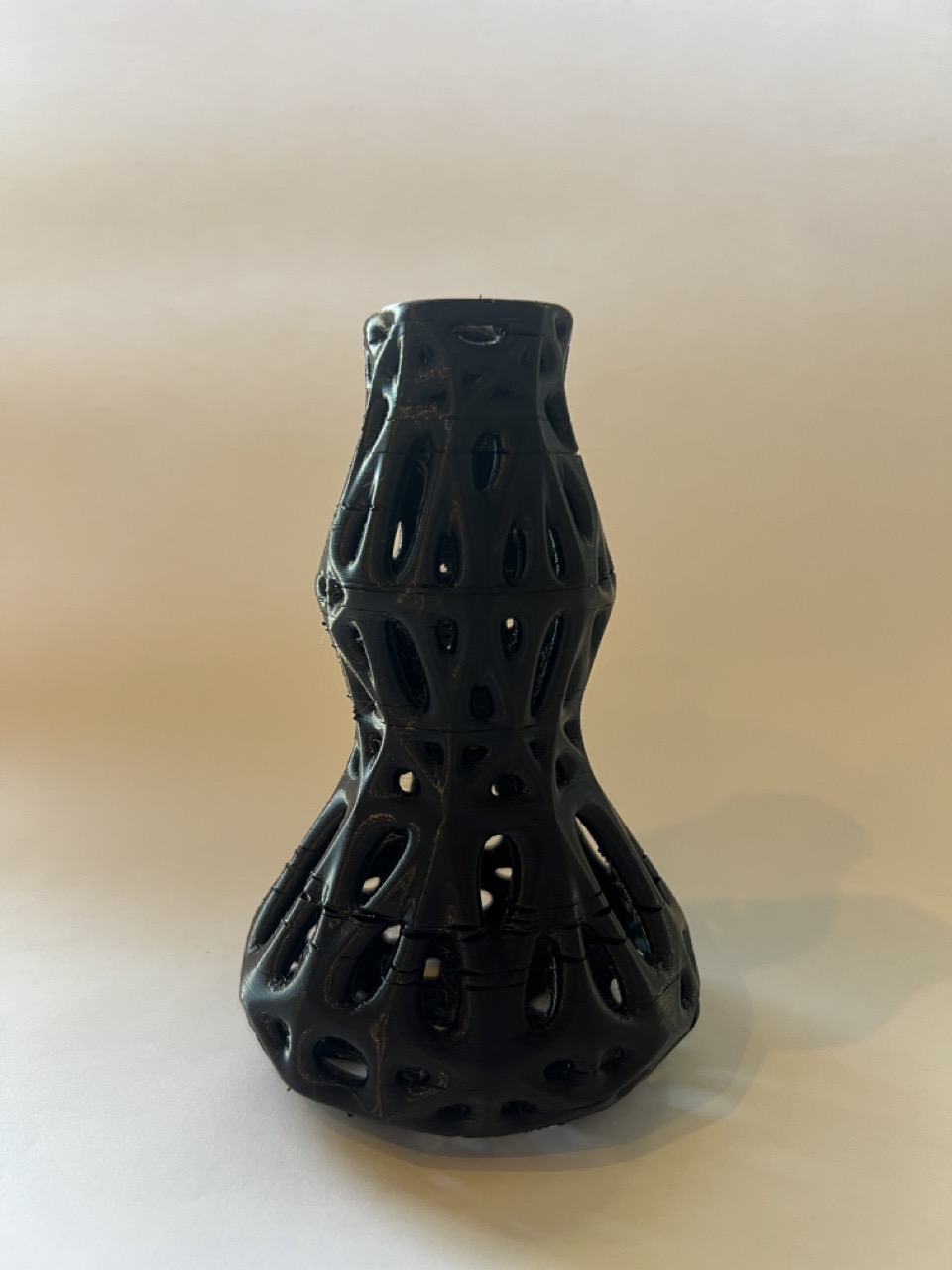
Before
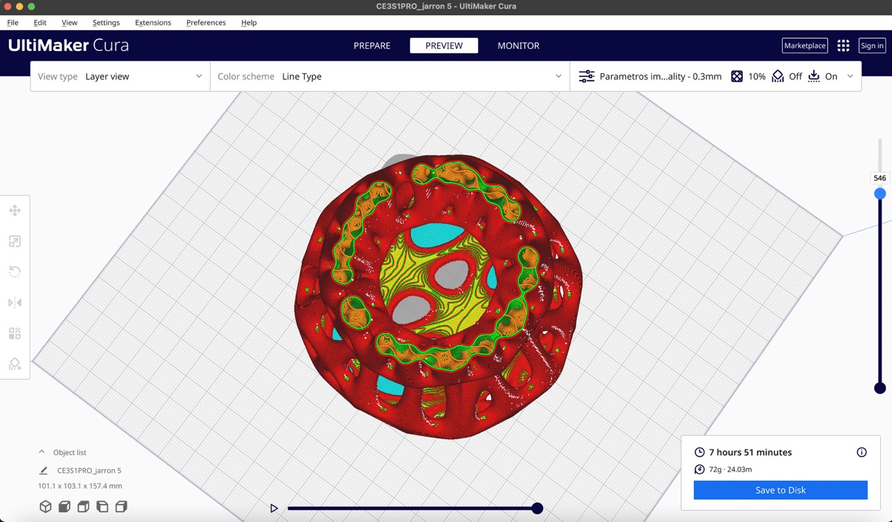
After
Although the file was prepared for printing with PLA filament, I opted to try using a resin printer instead. This will be my first time using resin, so I am excited to see the result!
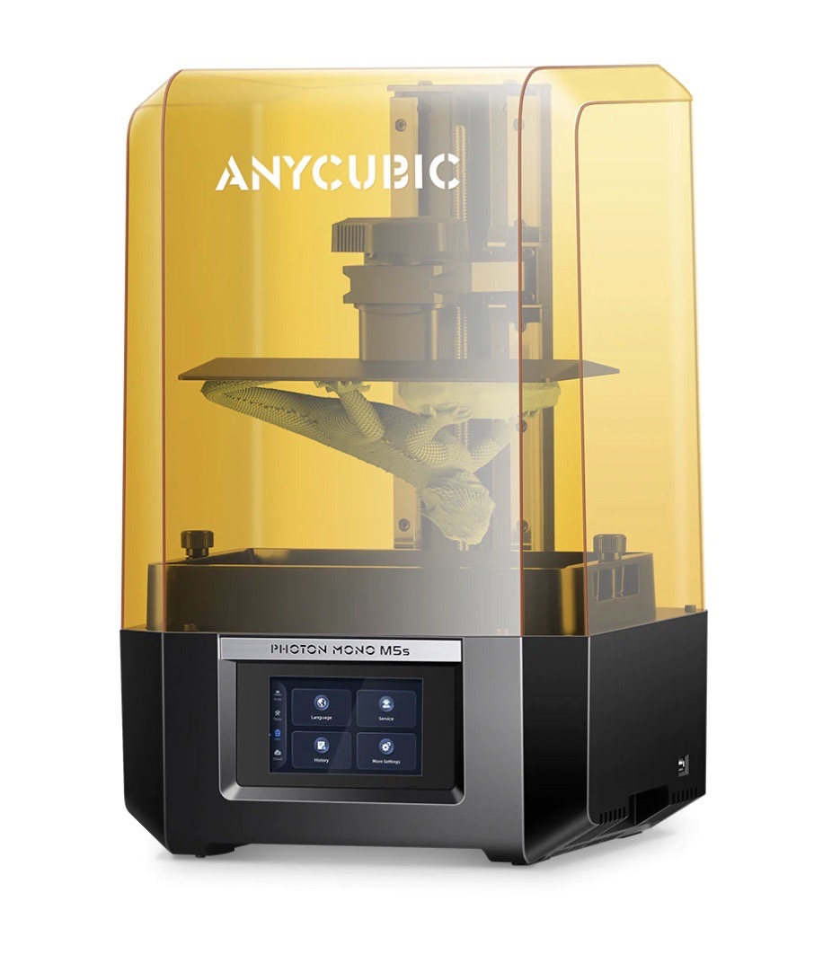
3D printing resin
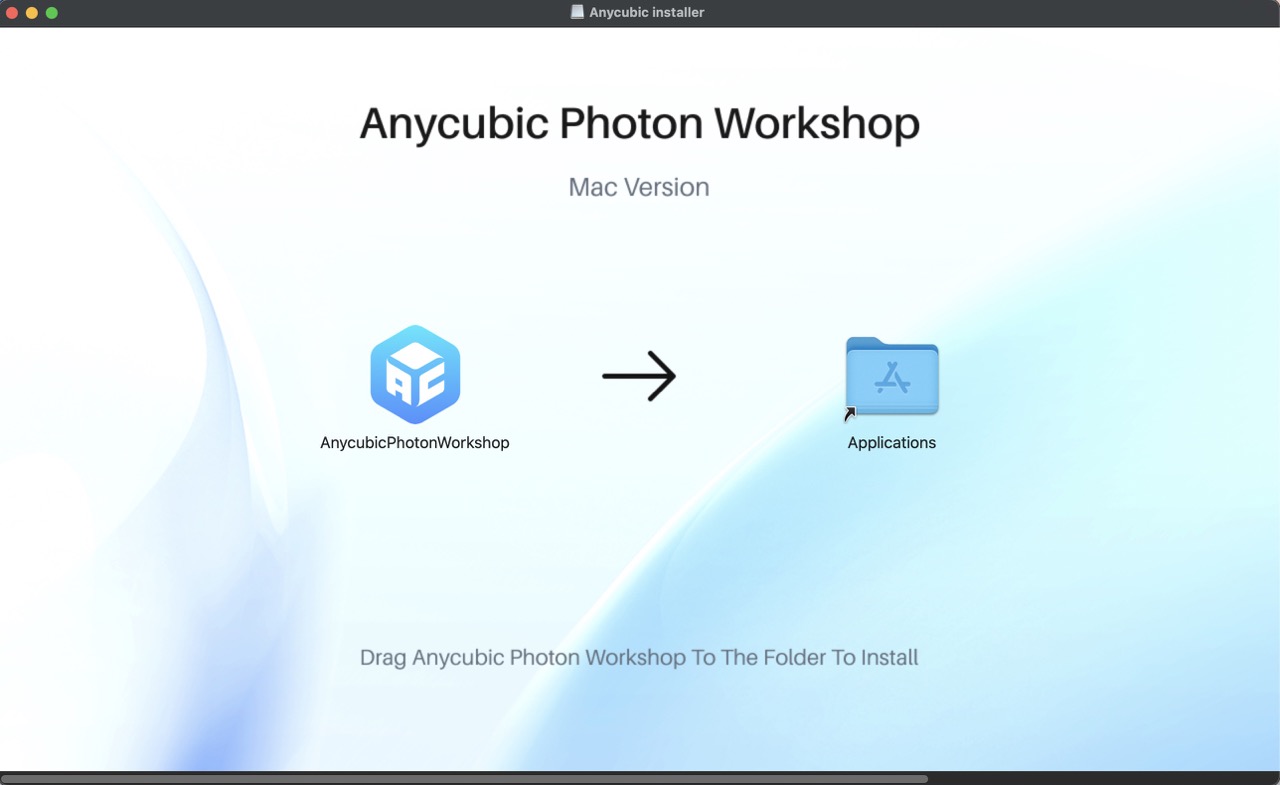
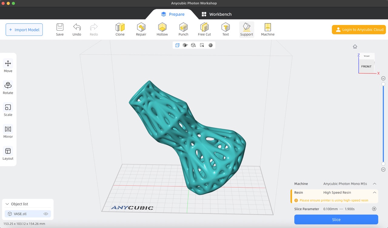
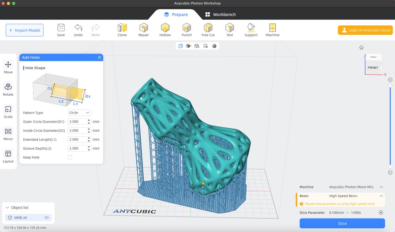
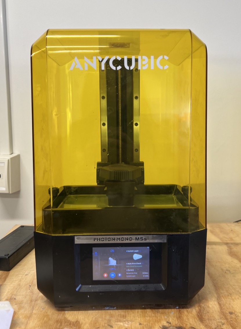
I'll be using the Anycubic Photon Mono M5s
- To start, I downloaded the AnycubicPhotonWorkshop software from this link.
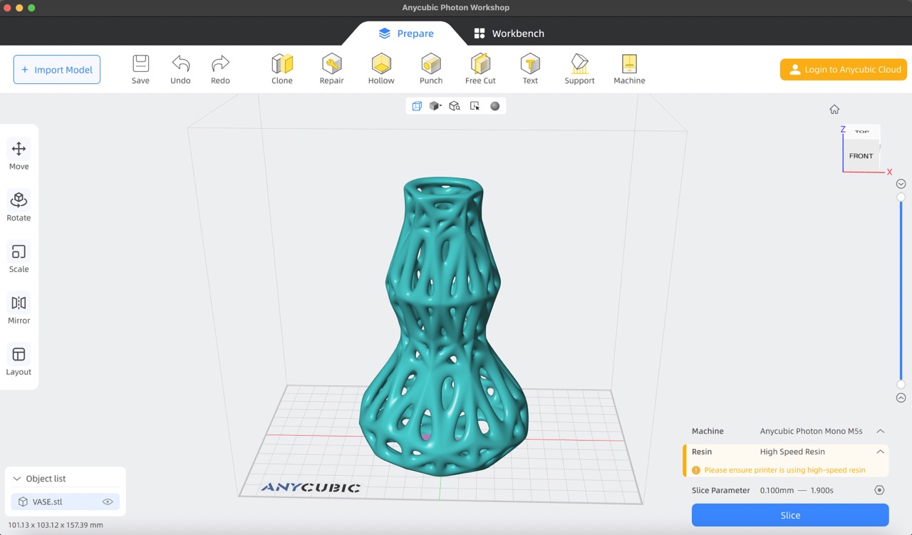
- I then imported my STL vase model into the software.
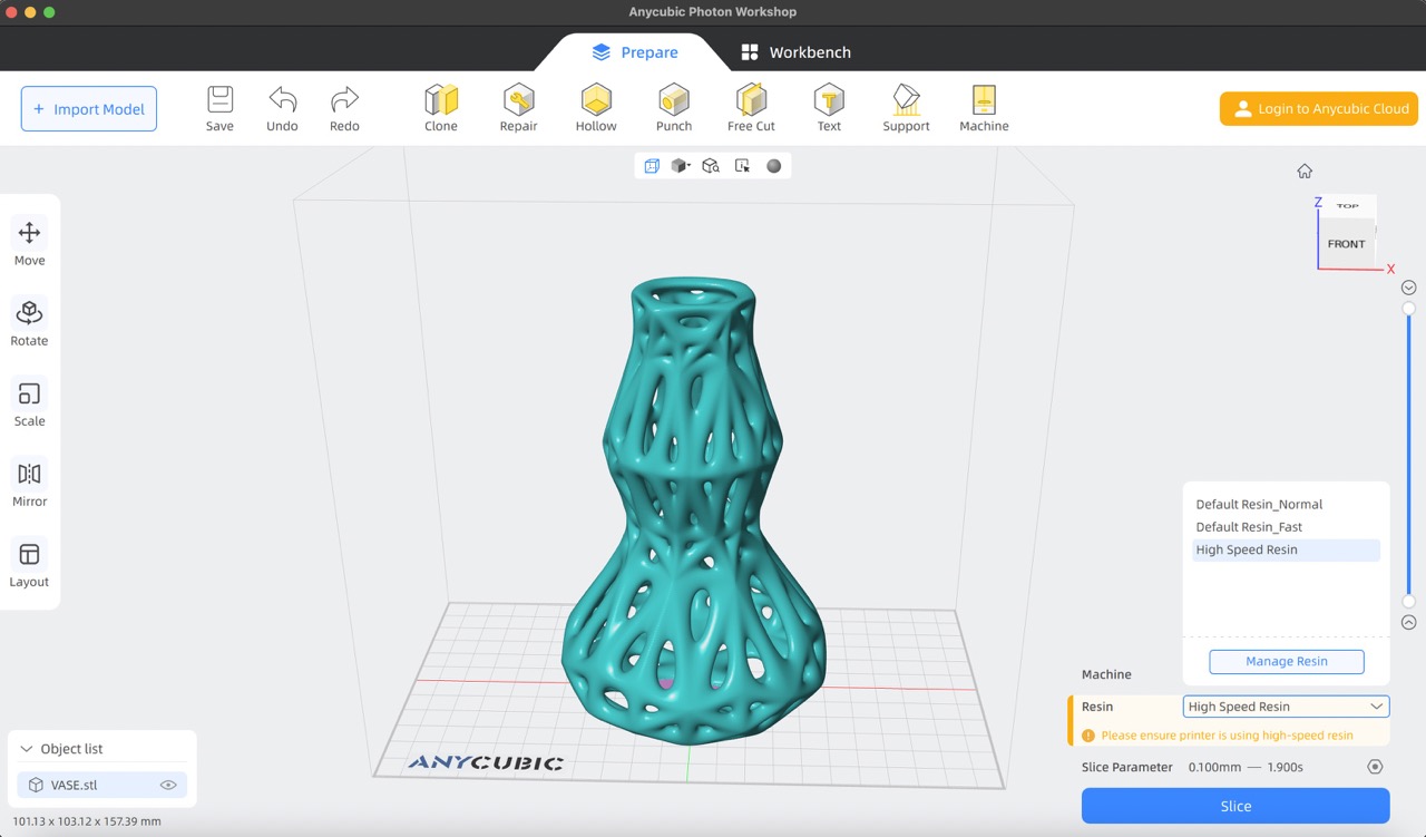
- I chose the 'High Speed Resin' as the resin type for printing.
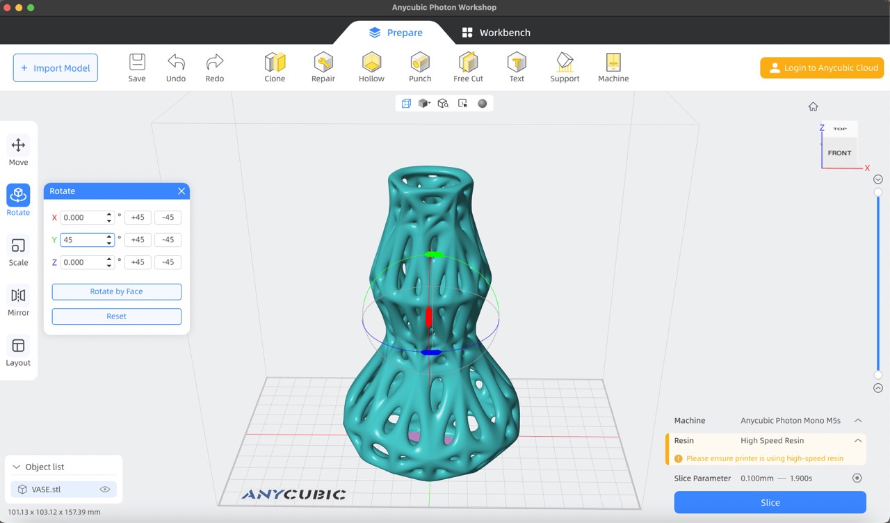
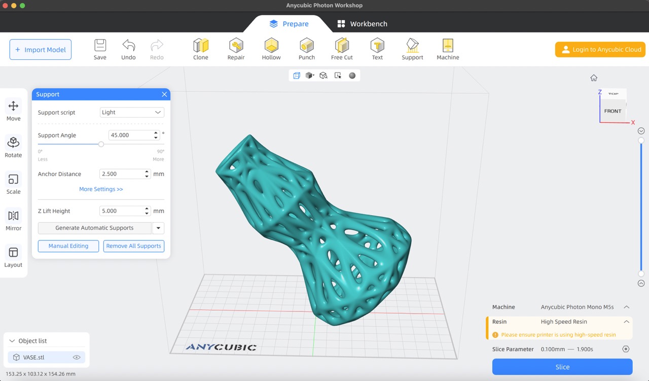
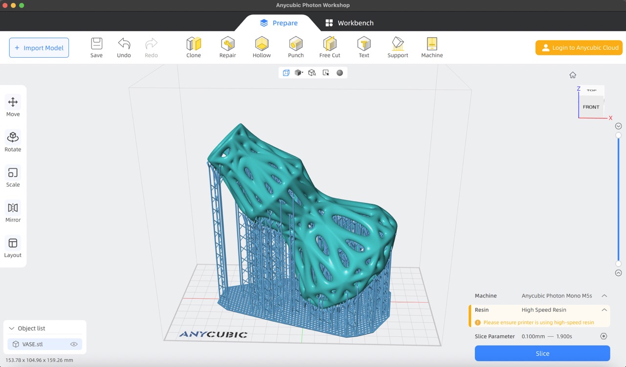
- Using the 'rotate' tool from the left-hand side toolbar, I rotated the model 45 degrees.
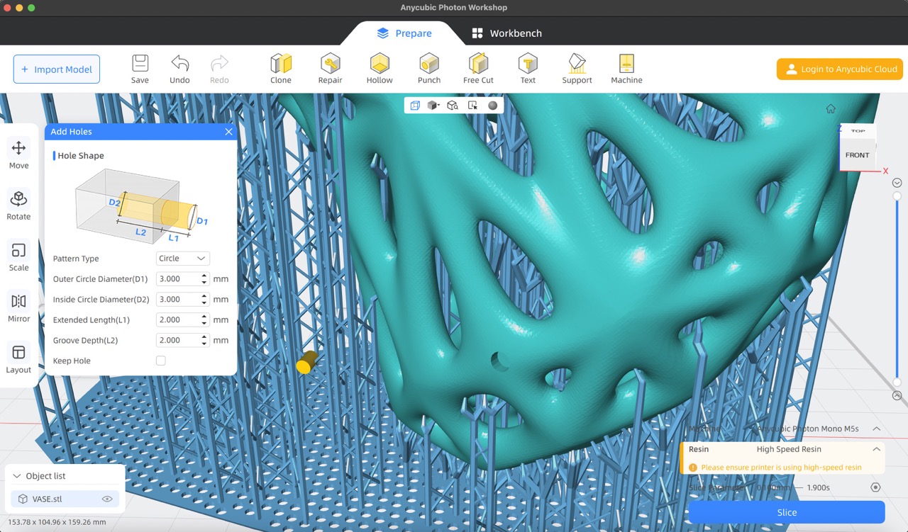
- I generated supports using the 'support' tool from the top toolbar. I adjusted the 'support script' to 'light'.
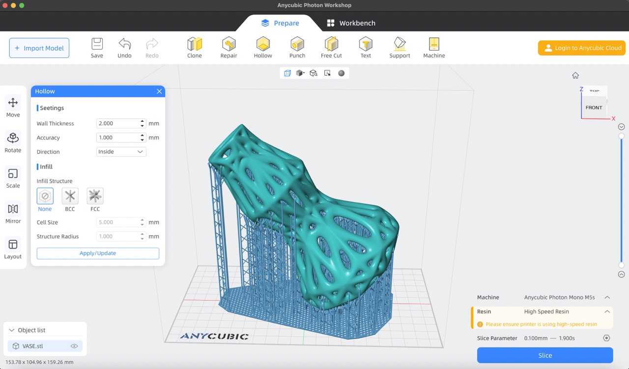
- To hollow out the object, I selected the 'Hollow' tool and set the wall thickness to '2 mm'.
- Using the punch tool, I created a hole with a diameter of 3 mm to allow resin to flow out once printing is complete.
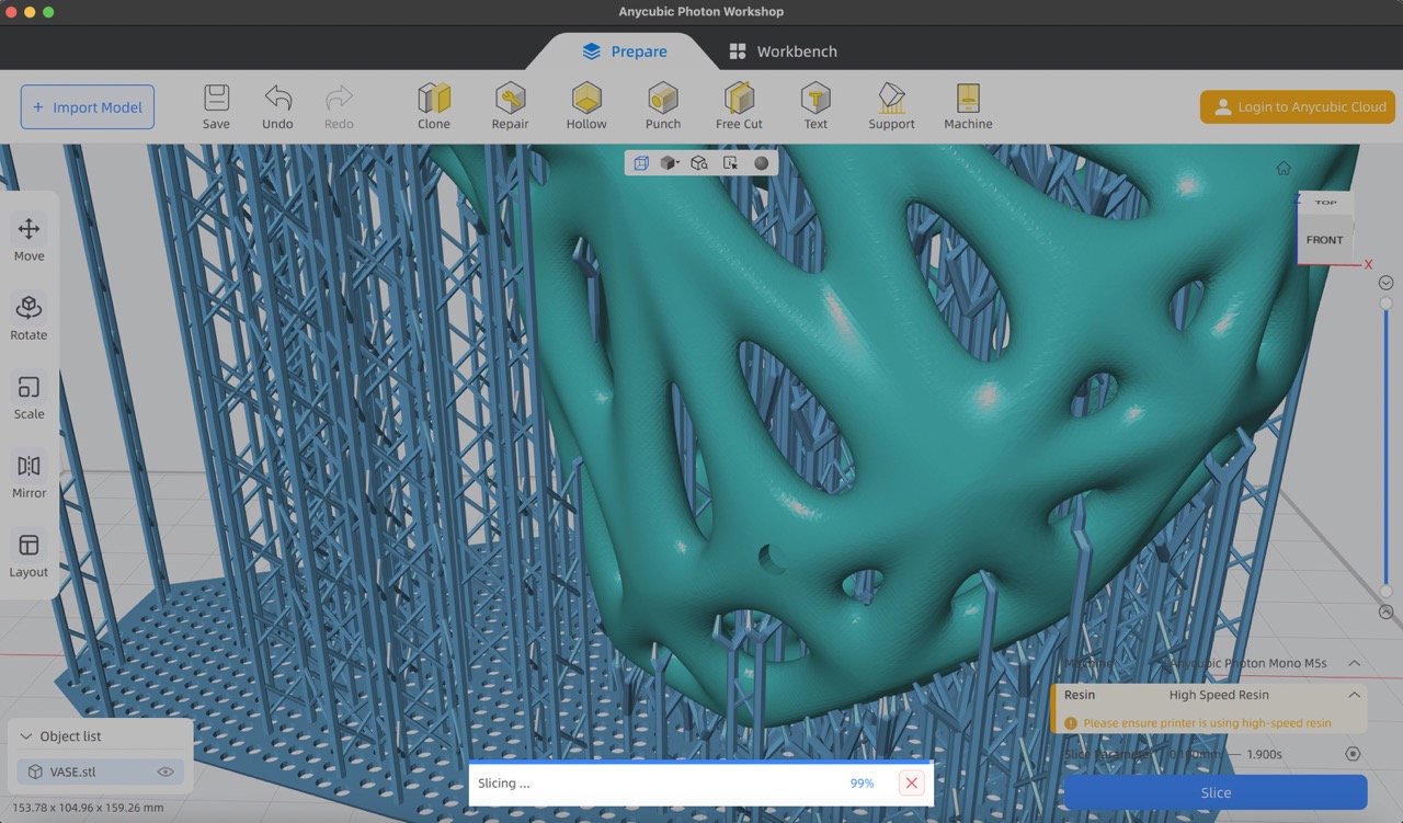
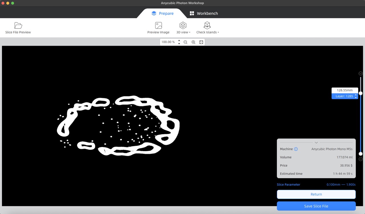
- Finally, I used the slice tool to generate and save the slice file to a USB drive for printing.
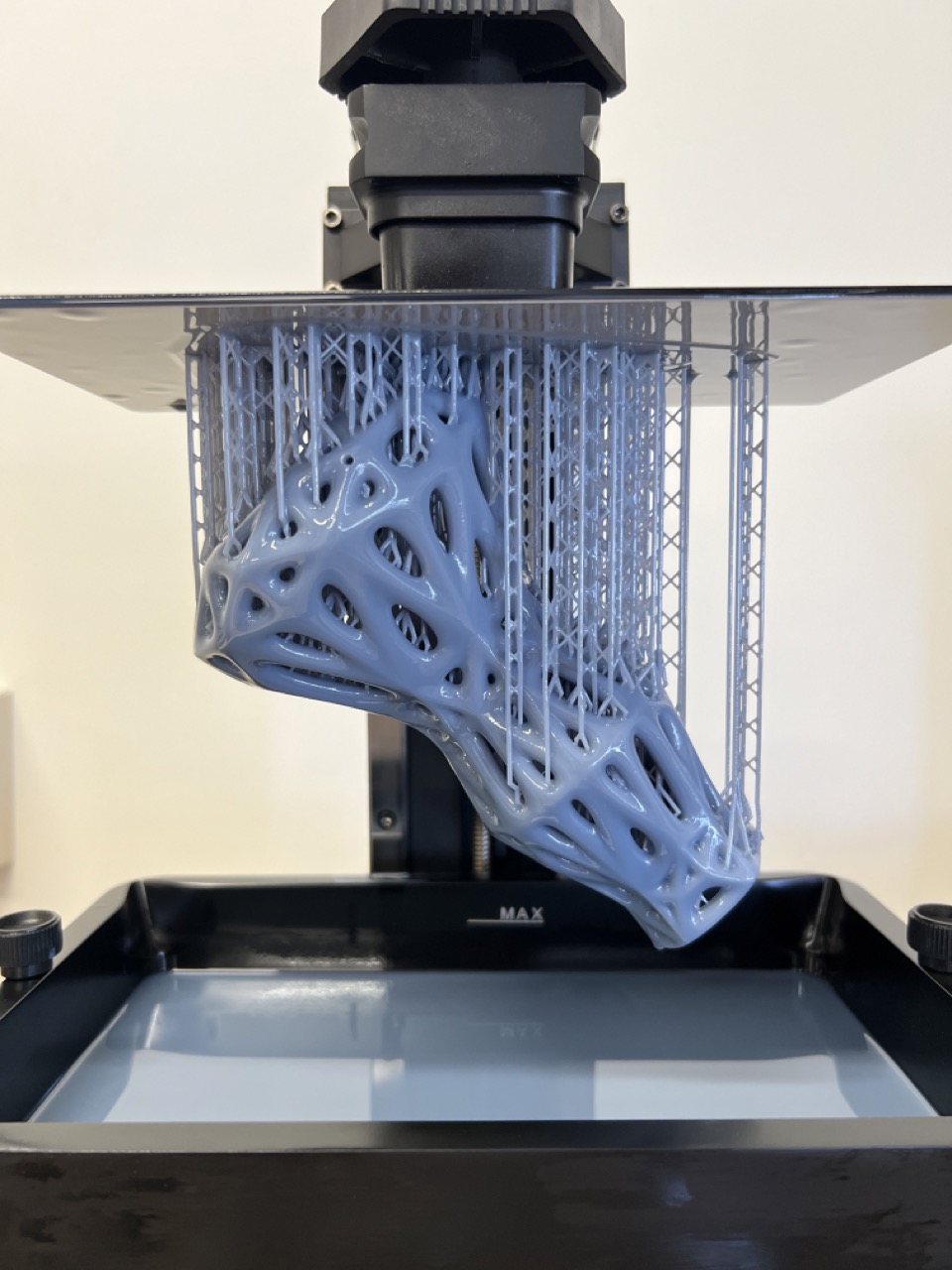
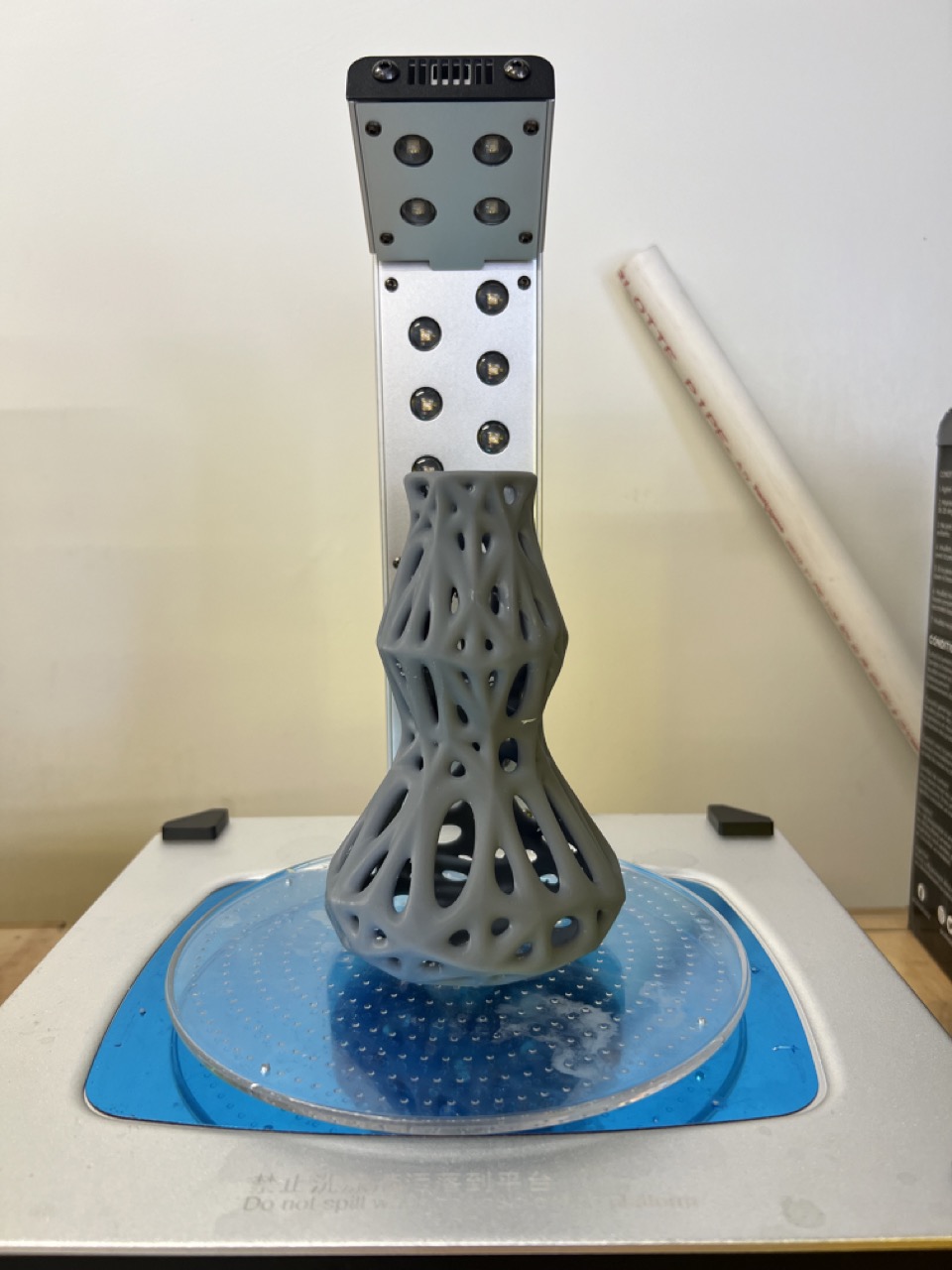
Let's print!
- Insert your file into the printer via USB and select the file to start printing.
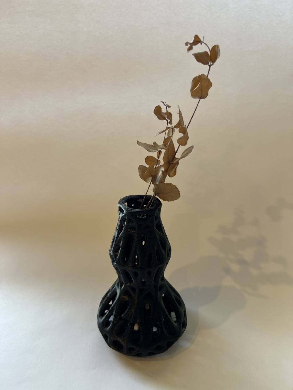
- Once printing is complete, your result will resemble the model you designed.
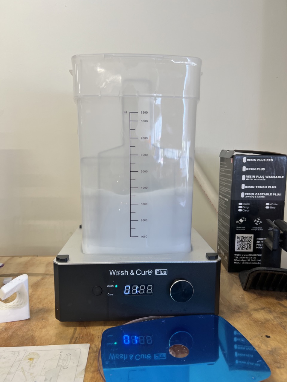
- Carefully remove it from the printing base and place it in alcohol for 5 minutes to clean off any excess resin.
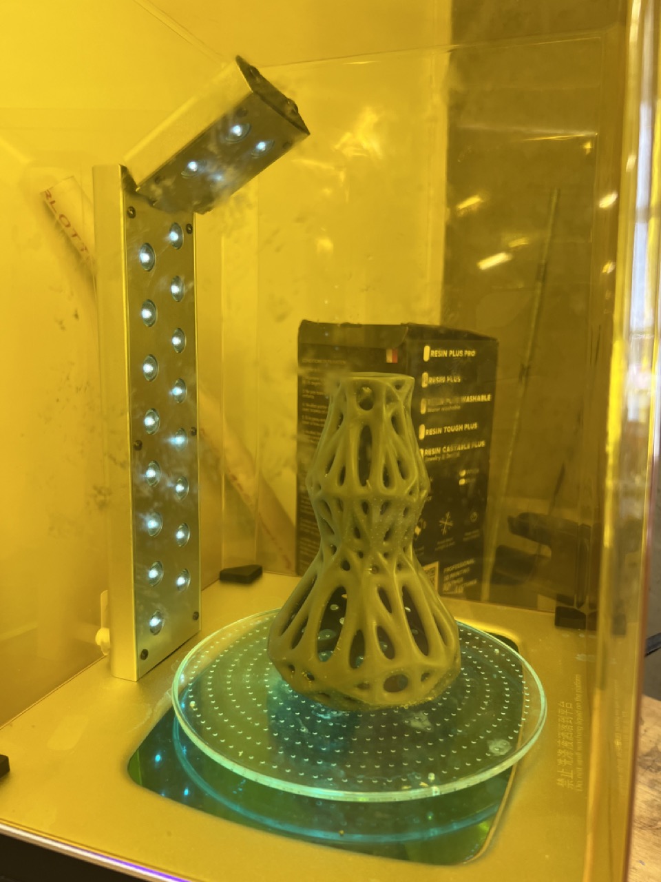
- Remove the support material and cure the model for 10 minutes to solidify the resin.
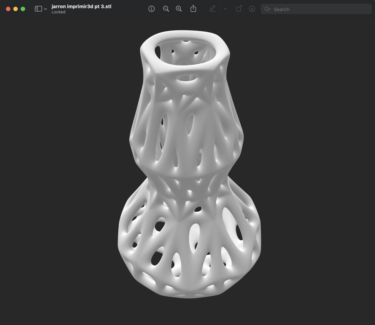
- This is the final result.
**Post-production:
I'll need to sand the areas that were in contact with the support material for a smoother finish. Additionally, I'll consider the option of painting and further finishing the model to enhance its appearance.
3D print files
Reducing the STL file size for uploading to my webpage proved to be quite a challenge. I tackled this by using Blender's Decimate modifier with a ratio of 0.01. While this did reduce the file size, the geometry lost some of its smoothness.
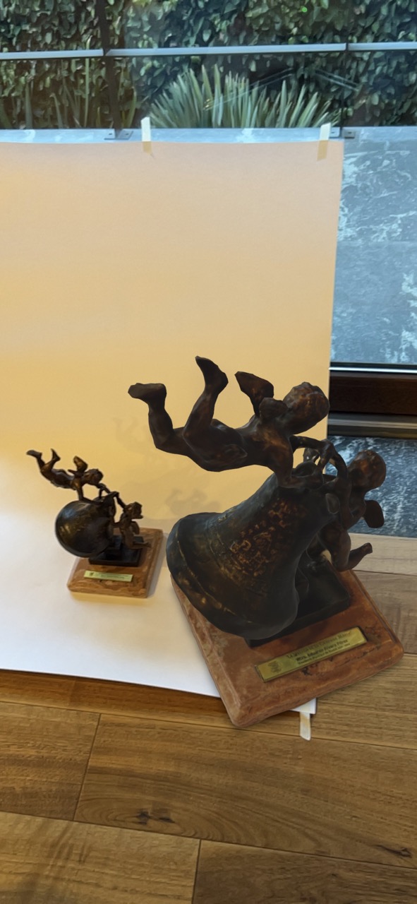
3D scanning
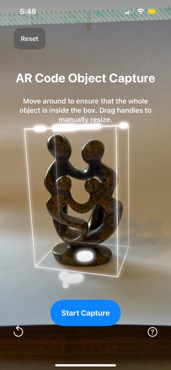
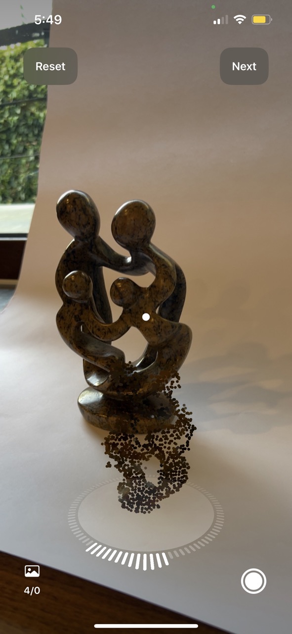
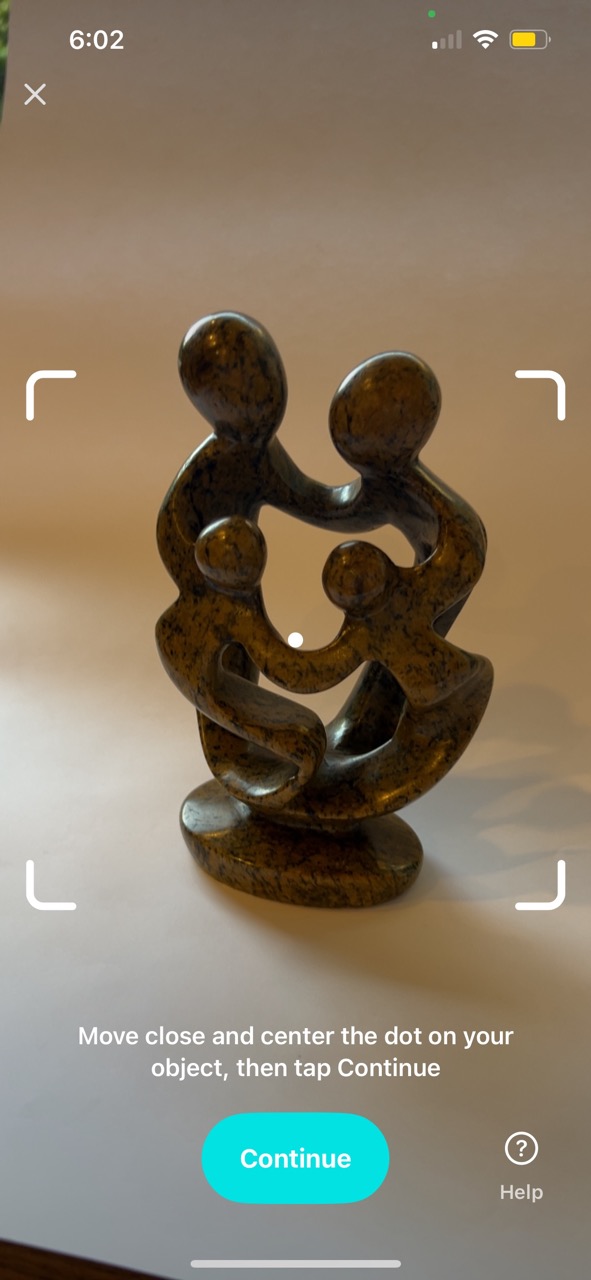
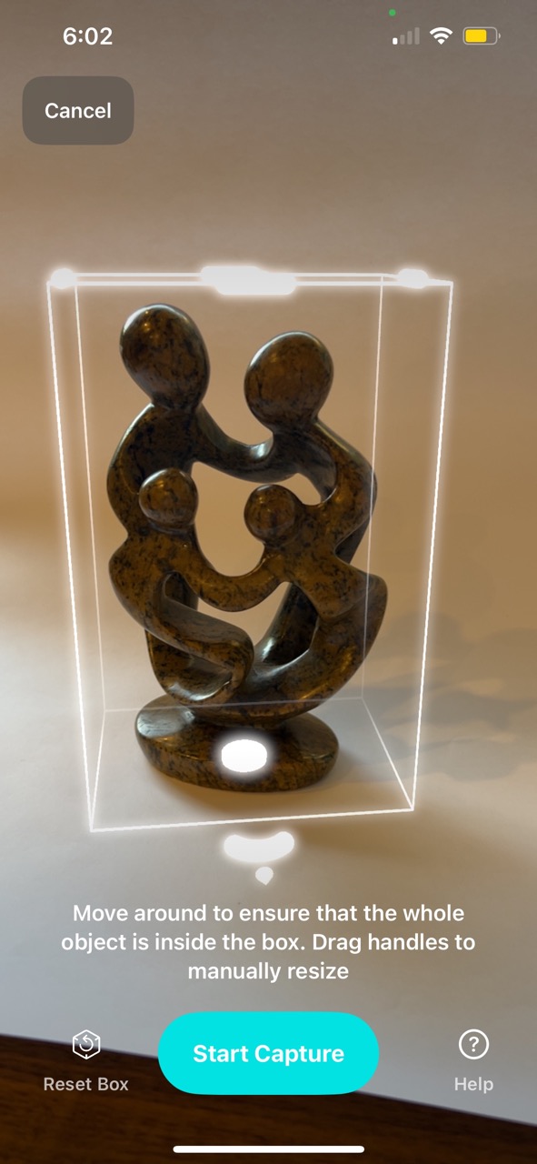
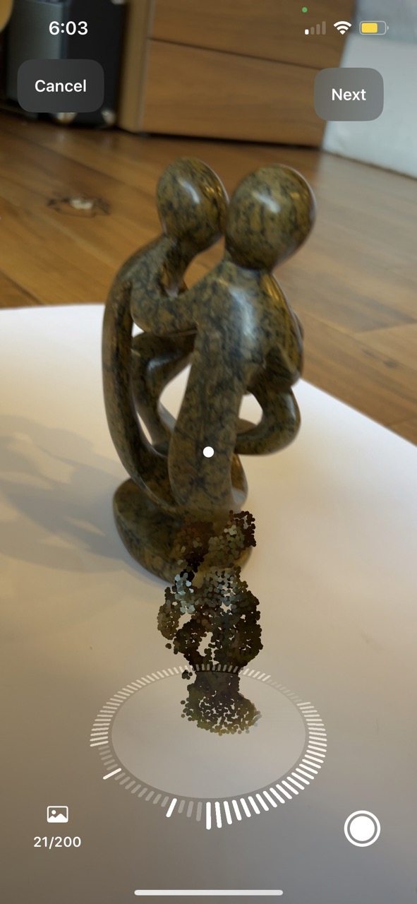
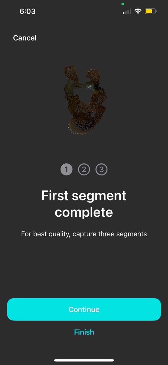
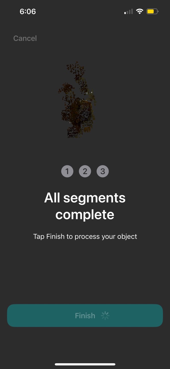
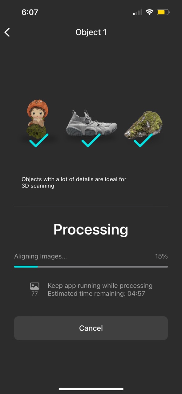
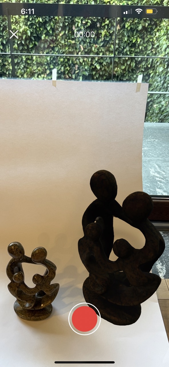
For the 3D scanning assignment, I decided to compare two different apps: KIRI Engine and AR Code. My approach involved scanning the same object using both applications to assess their performance. I will show the scanning process using both of these apps as well as my findings:
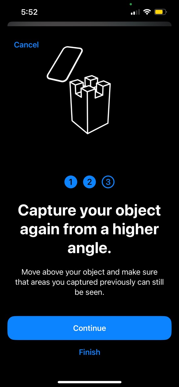
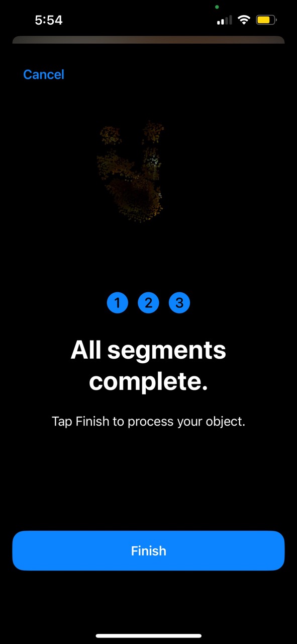
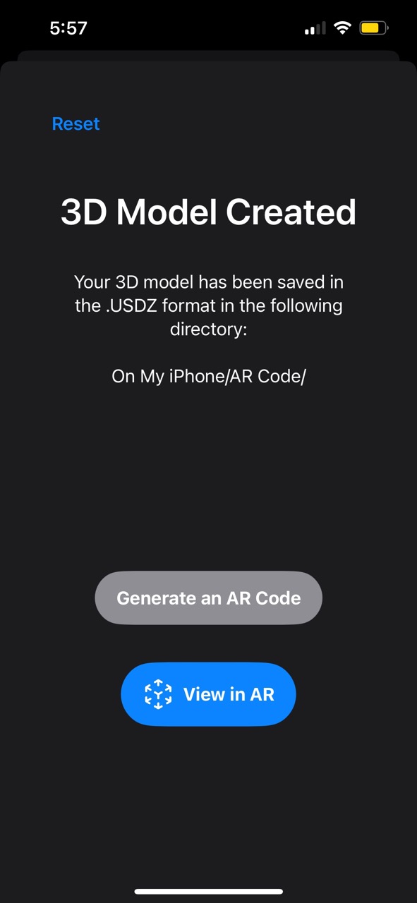
AR Code

KIRI Engine
Comparison:
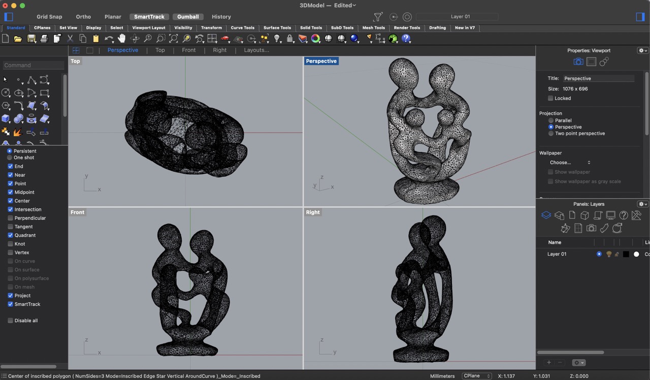
Both of these apps are pretty much alike. They have almost the same interface for scanning a model. The only differences really depend on what you want to do with the scan. If you're into augmented reality, the AR Code app is the way to go. But if you're planning to print or modify the scanned object in a modeling software, then the Kiri engine is better. The image below shows the .obj file I scanned and opened in Rhino.
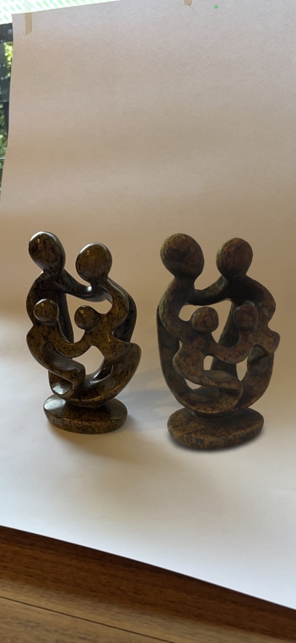
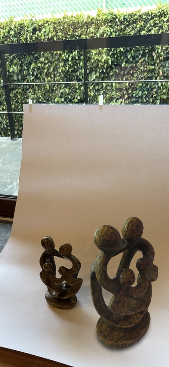
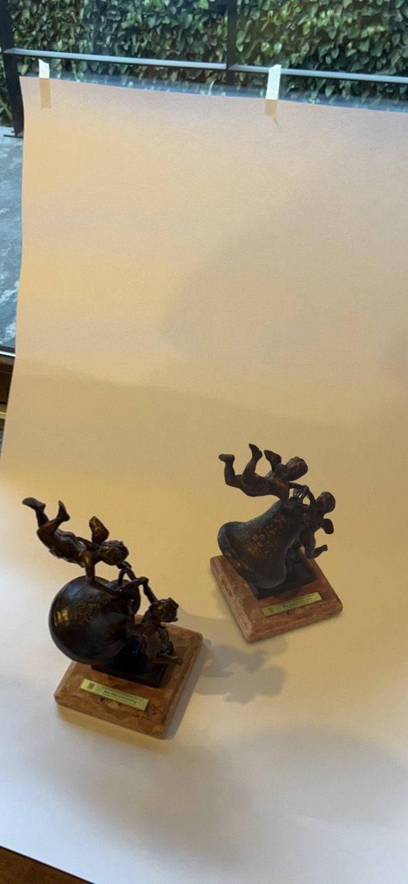
Extra scans with AR code
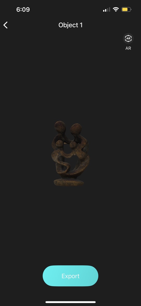
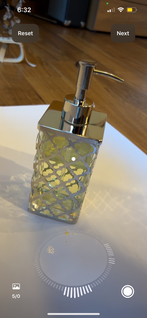
I also explored scanning various objects I found around my house and was impressed by the quality of textures represented in augmented reality.
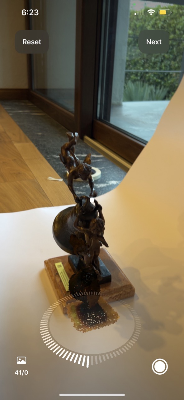
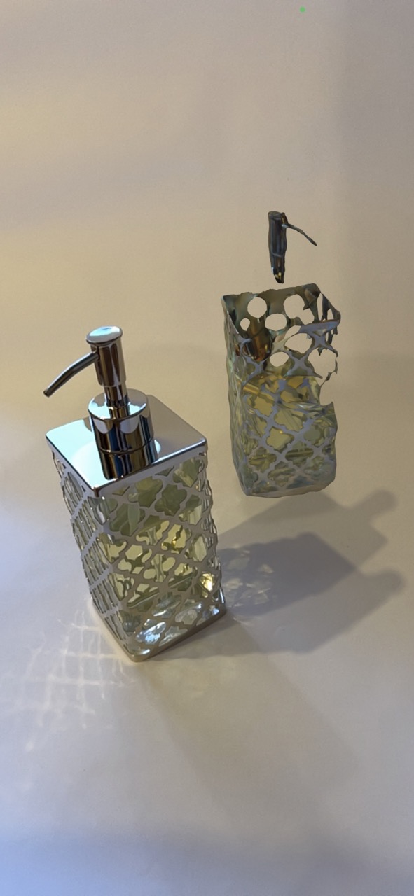
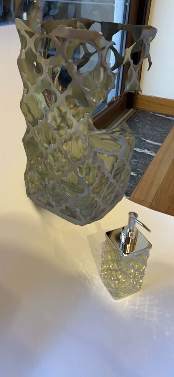
Additionally, I attempted to scan a reflective object to observe its scanning process, but as expected, it did not work. From now on, I will try to avoid these types of materials for scanning purposes.
Conclusions
This week has been fundamental for my growth as a designer. By understanding the scope of these tools, I aim to improve my efficiency in design creation and expand my opportunities within the field.