3. computer controlled cutting
During this week we had to design and lasercut a parametric construction kit accounting for the lasercutter kerf and cut something on the vinyl cutter. In our group page, you can find the documentation of the examples used to find the kerf, the parameters to obtain a clean cut as well as examples of different types of joints and flexible hinges.
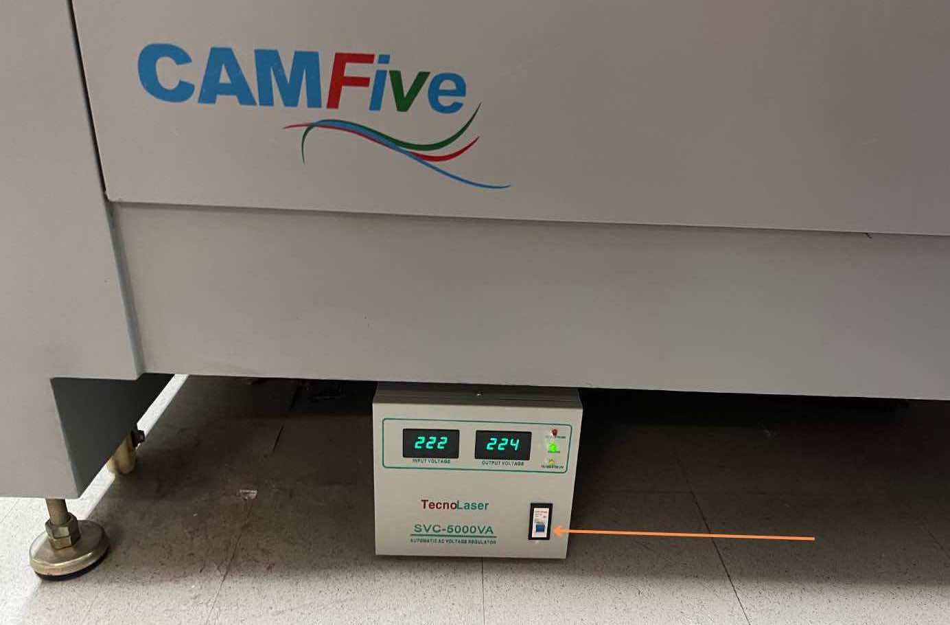
Learning how to set up the the CAMFive laser cutter
I attended a class with Alberto Blanco, one of our instructors, to learn how to use the CAMFive laser cutter and Smart Carve software.
Steps to use the CAMFive laser cutter:
Turning On the CAMFive Laser Cutter:
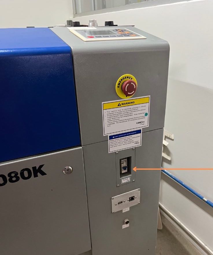
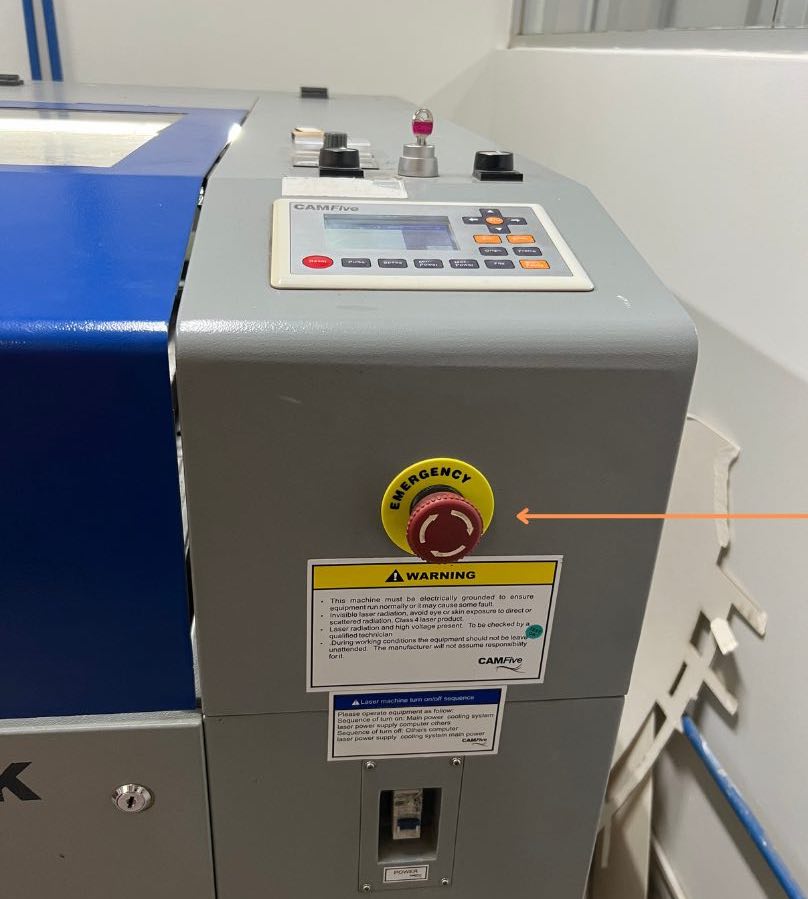
- Locate and turn on the switches for the machine's fan (bottom) and the one on the right-hand side to turn on the machine.
- The emergency switch, situated on the top-right side, is always on for safety. Rotate it to the right to unlock it.
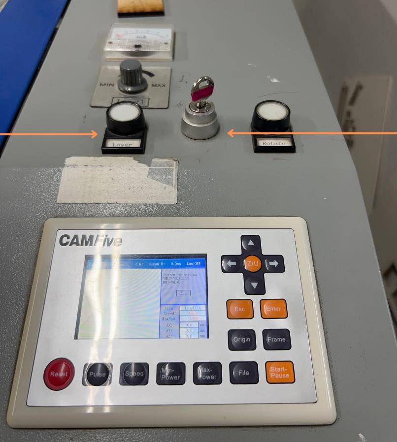
- Insert the key located on the top of the machine and turn it to power on the device, then activate the laser by pressing the white circular button.
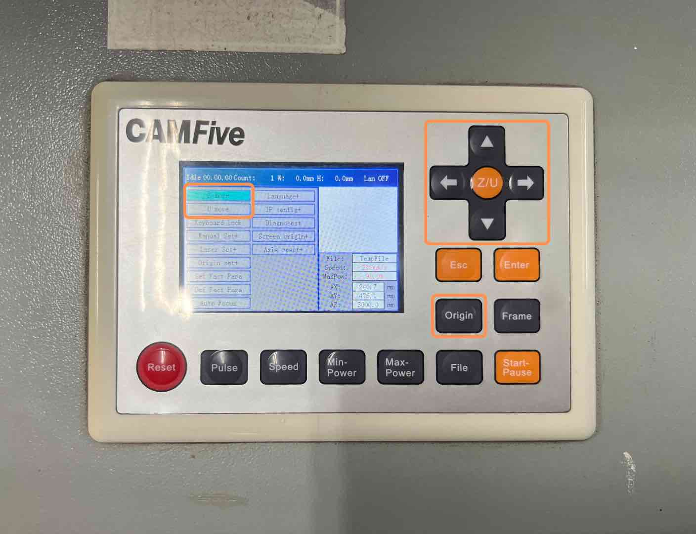
Machine setup:
- Using the CAMFive screen, adjust the x and y axes using the arrow controls to define the point 0,0. It's recommended to set this point as the top-right corner of your material.
- Adjust the height of the cutter by selecting "z/u" and then "z move." Place a 5 mm thick reference material and bring the laser down until it touches this material.
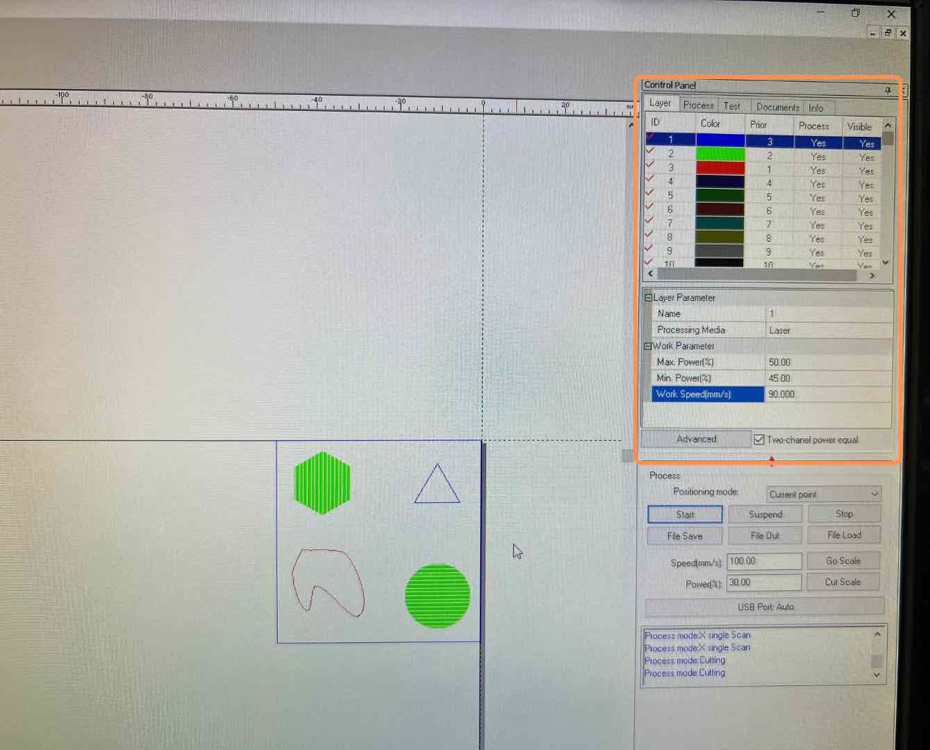
File upload and setup:
- Launch the laser cutter control software, "Smart Carve," on your computer.
- Create a new file directly within the software or import a file in .dxf format, ensuring to select the appropriate unit system.
- Experiment with different cutting, engraving, and filling parameters. For example, you can fill shapes by right-clicking and selecting the fill option, adjusting parameters like max power, min power, and speed based on your material and desired outcome.
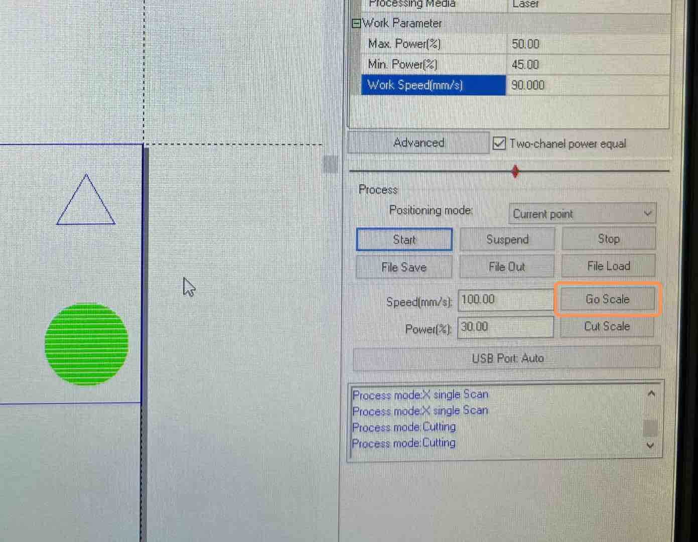
Check and start cutting:
- Use the "Go scale" button to verify that the trace fits your material and that the 0,0 point is correctly positioned.
- Once satisfied, click the start button to begin the cutting process.
Safety
- Turn off the laser and wait for it to completely power off before safely removing the material.
Tips
Always check:
- Power
- Speed
- Height
Recommended cutting order:
- Start with engravings: engrave any designs or patterns onto the material first.
- Next, perform internal cuts: cut out any internal shapes or patterns.
- Finish with external cuts: cut the outline or external shapes of your design.
How I designed my Construction Kit in Fusion 360
I wanted to create a construction kit centered around the concept of free play, aiming to stimulate creativity. To accomplish this, I selected four fundamental shapes: square, triangle, circle, and a flexible rectangle. I believe that the versatility of these shapes offers limitless possibilities for construction and creation.
Since I am very used to modeling in rhino, I decided to start modeling possible potential pieces using this software. After finalizing the designs, I transitioned to Fusion 360 to create parametric models. Here are some of the initial models:
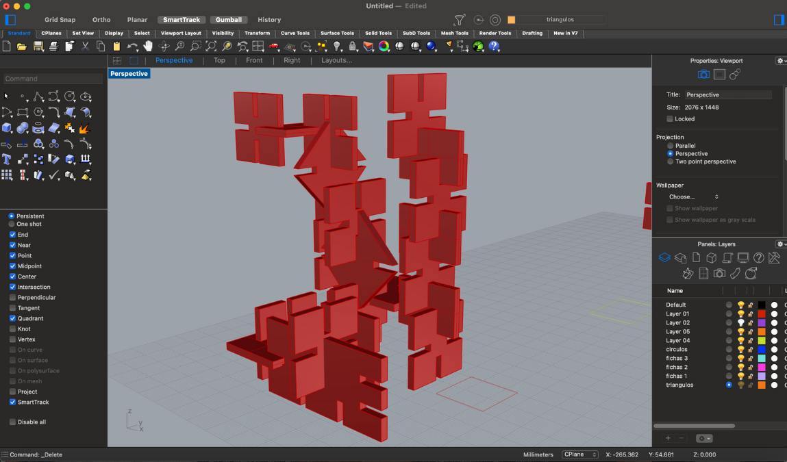
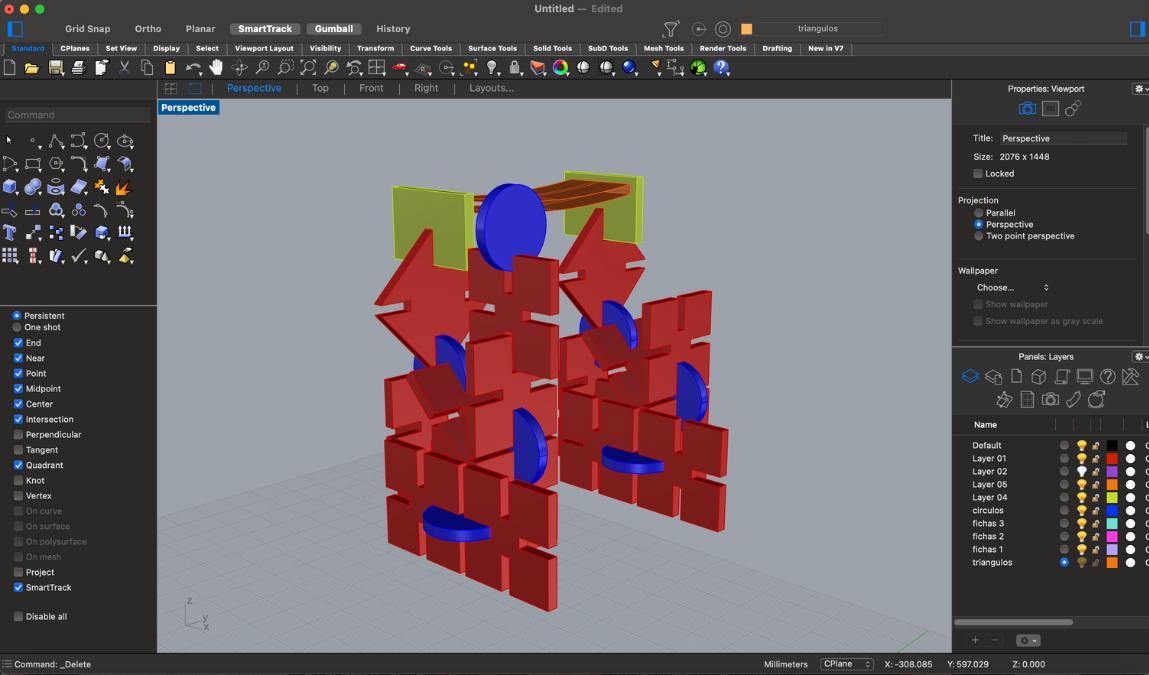
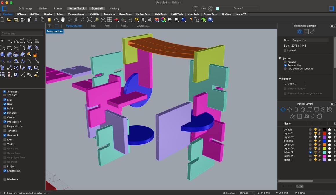
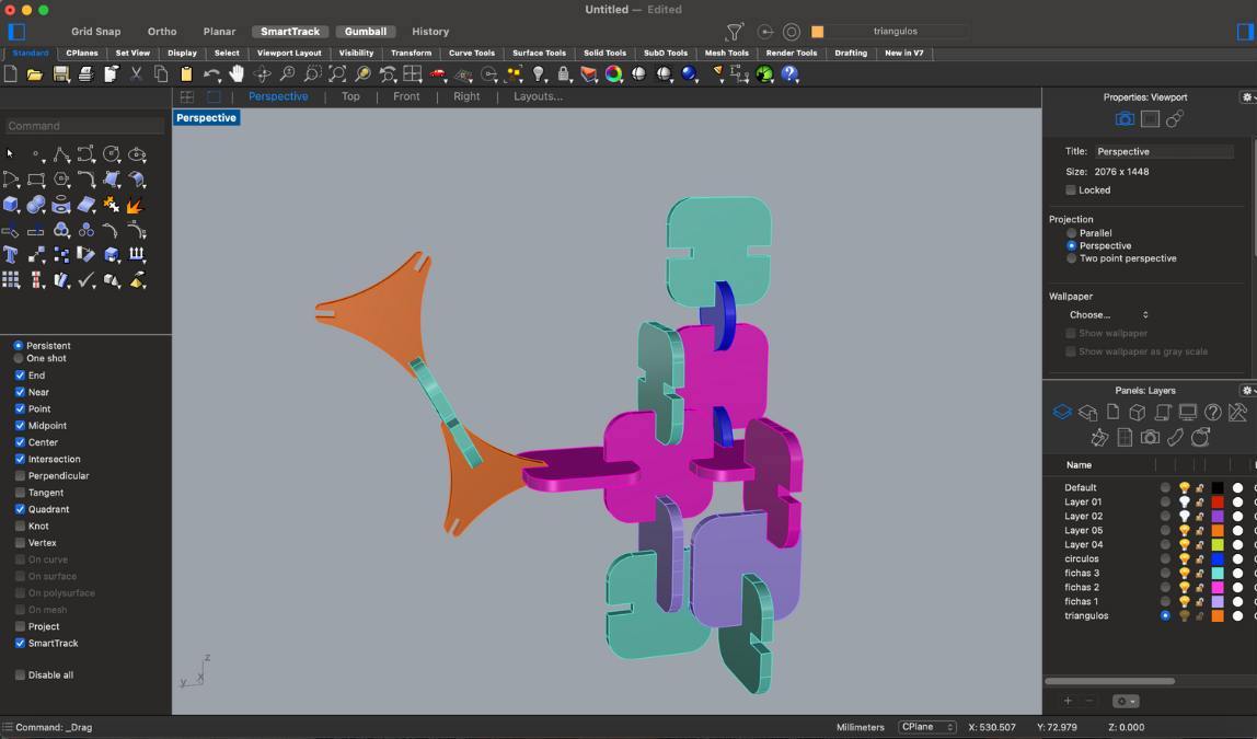
After I got a better idea of the different pieces I wanted to create, I opened up Fusion 360 and began sketching and designing each one of them with their respective measurements.
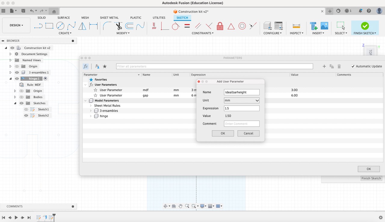
- MDF Parameter: Created with a value of 3 mm to represent the thickness of the MDF material.
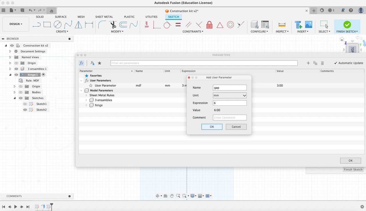
- Gap Parameter: Established with a value of 6 mm to define the desired gap between components.
- IdealBarHeight Parameter: Set to 1.5 mm to specify the ideal height for bars.
- The triangles are too thin and fragile
- During assembly, the pieces almost touch each other, so it is necessary to reduce the depth of the joints
- The kerf was not right and the problems with the laser cutter resulted in loose pieces that made it impossible to create large structures
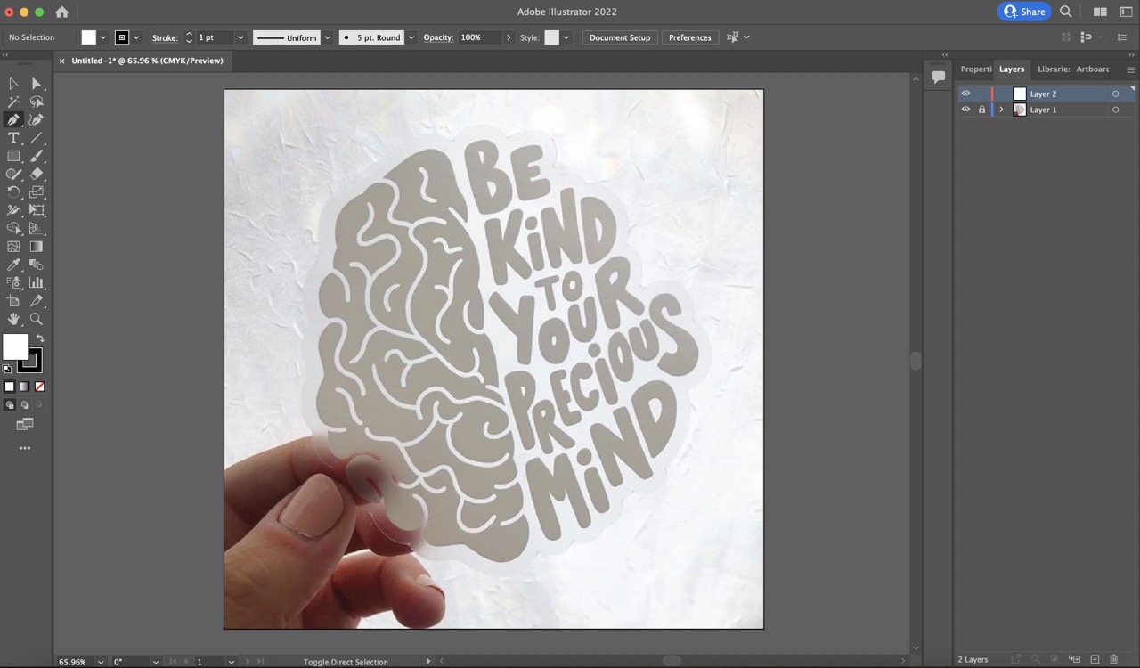
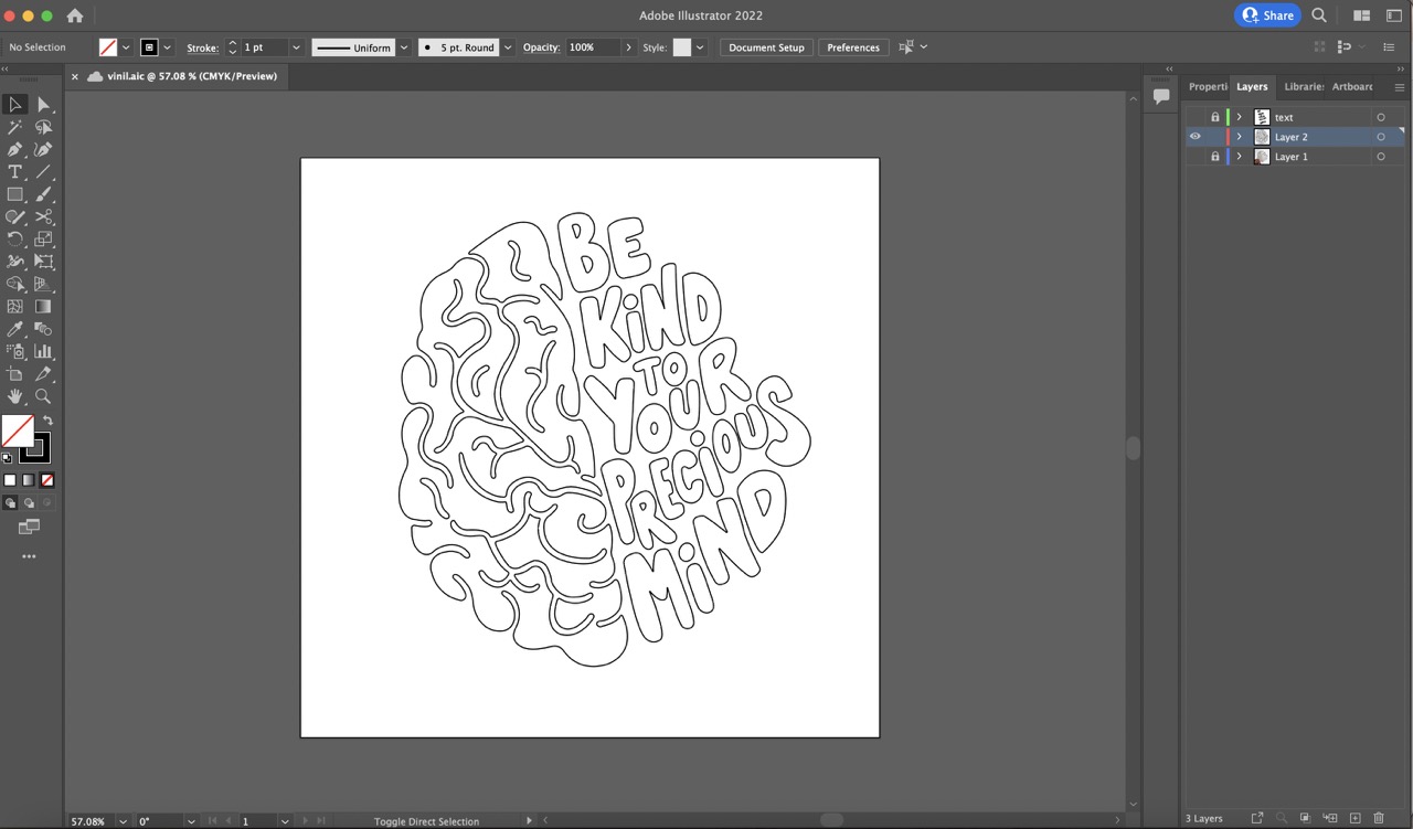
- To create the cutting file, I chose to use Illustrator. First, I imported the picture I wanted to replicate.
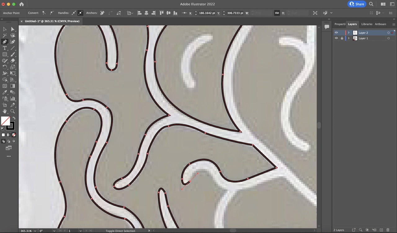
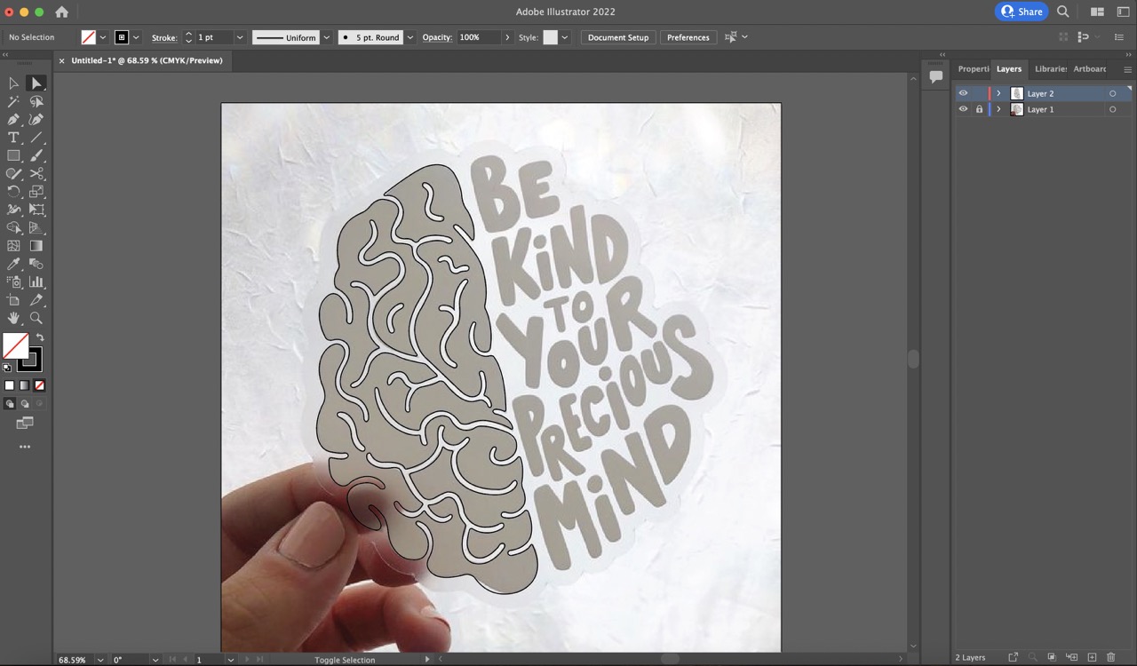
- Then, I used the 'pen tool' to trace each vector carefully. Once the tracing was complete, I used the 'Direct Selection Tool' to smooth out curves and adjust the curve handles as needed.
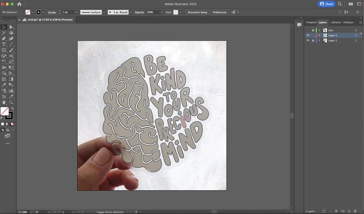
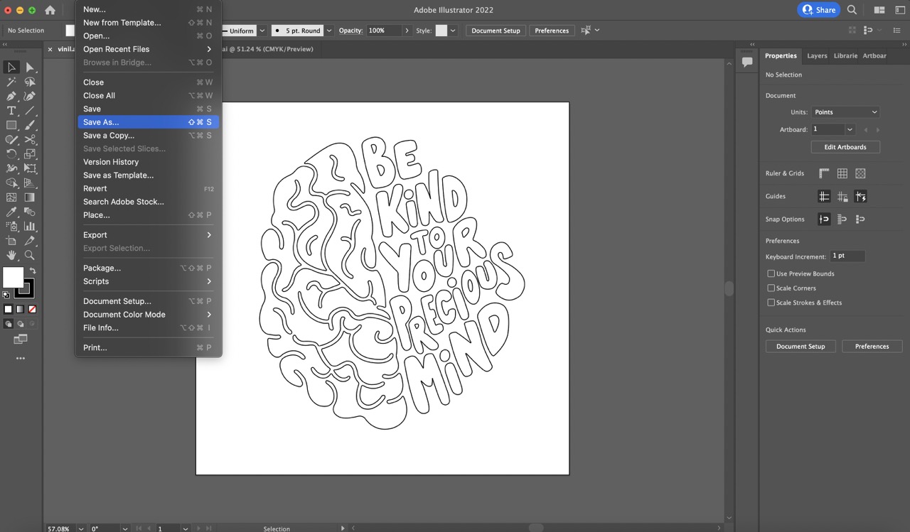
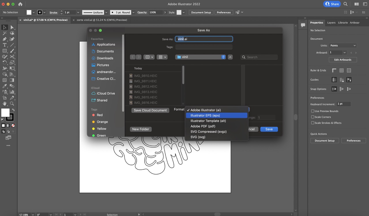
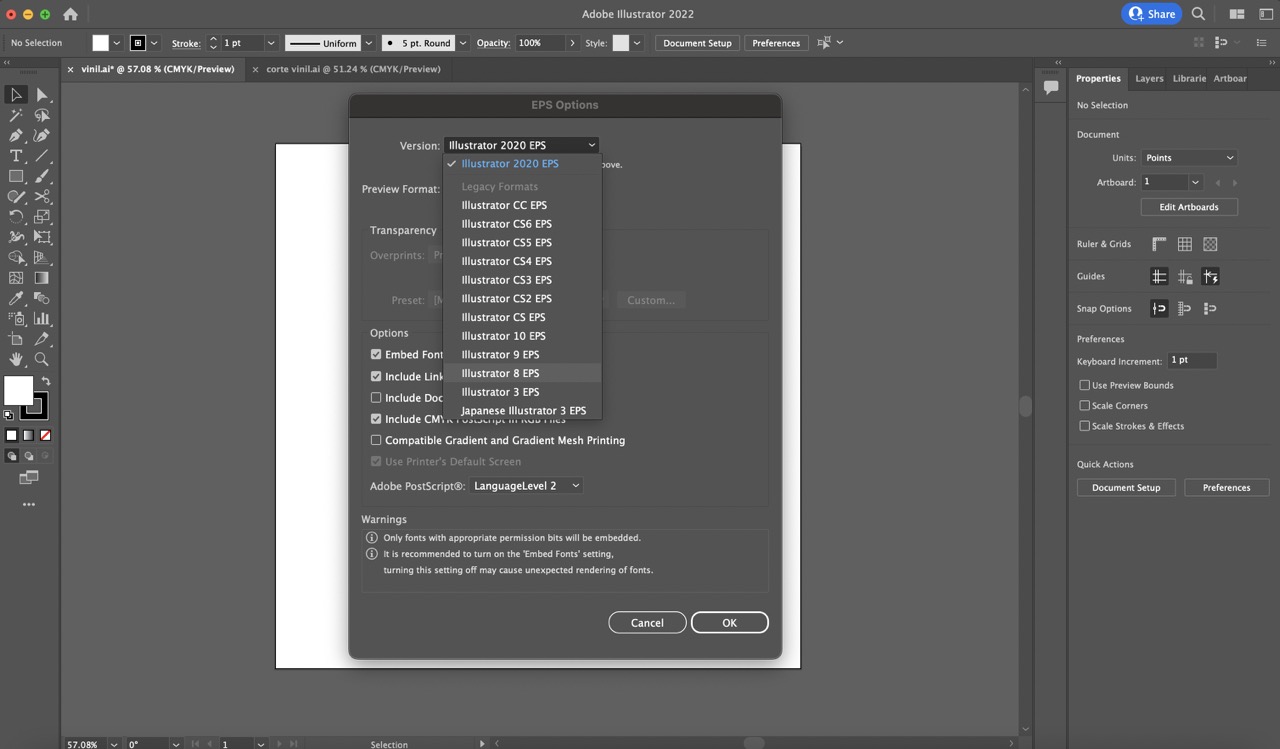
- To save the file, I went to the 'File' menu, selected 'Save As', and chose '(eps) format'. A window popped up, where I selected 'Illustrator 8 EPS' under the 'Version' dropdown menu.
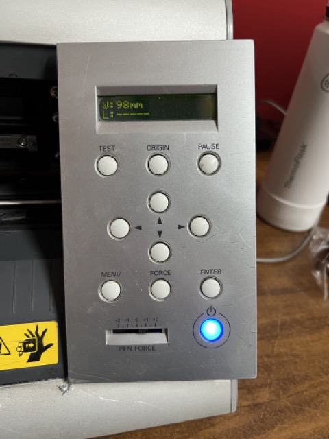
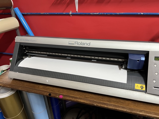
- To start, turn on the vinyl cutter and select the color of vinyl you'll be using for cutting.
- Next, position the vinyl roll at the back of the machine and pull it out from the edge.
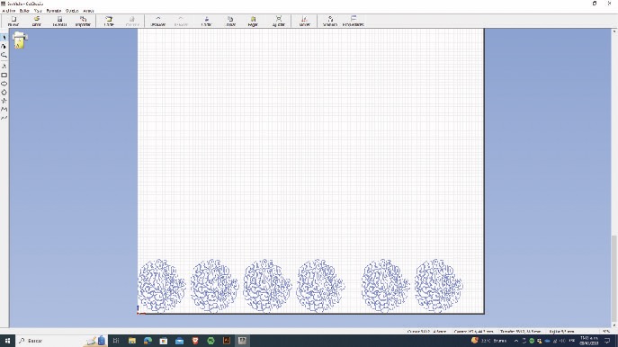
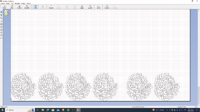
- Import your file into the software, in my case I used "Roland CutStudio".
- Press the 'cut' button in the software interface.
- The machine will immediately begin cutting your file onto the vinyl.
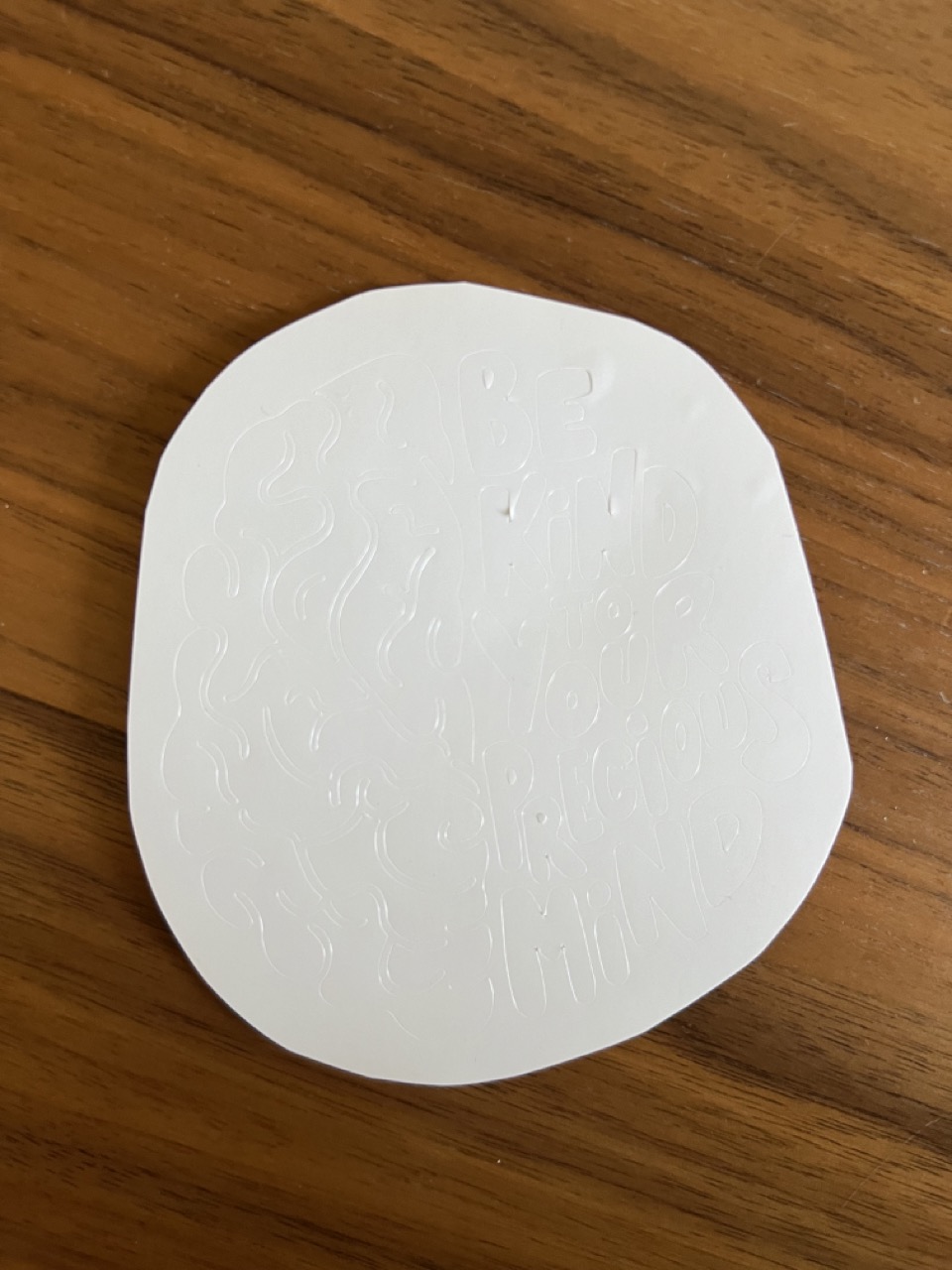
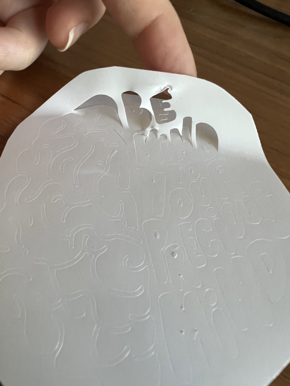
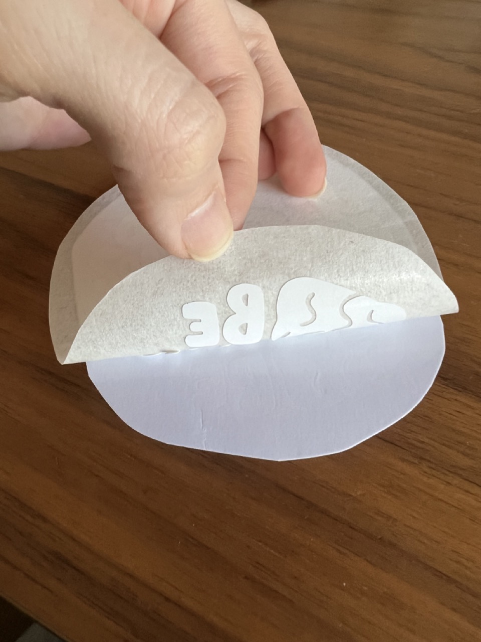
- Begin by trimming the surface of the vinyl cut to facilitate manipulation, ensuring to leave some extra space without cutting through the design.
- Using a thin-tip tool such as a punch or a thin cutter knife, delicately remove the excess vinyl by gently pulling it away, leaving only the desired design intact.
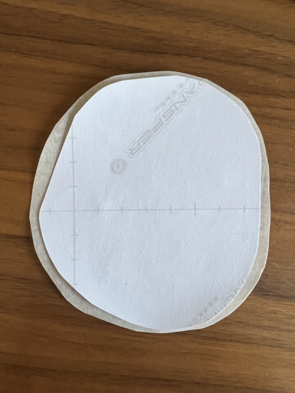
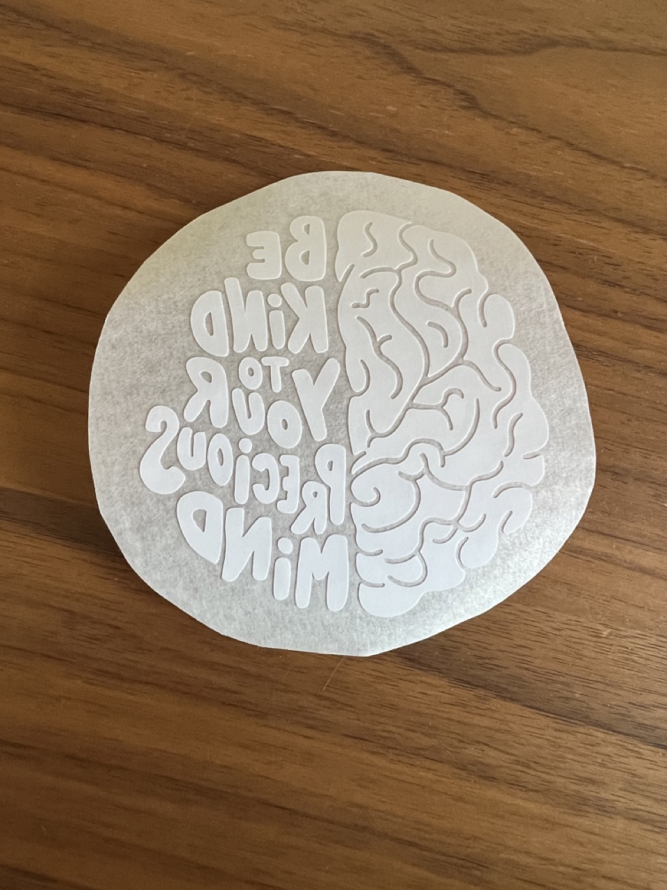
- Transfer the design onto transfer paper, ensuring it sticks correctly.
- Gently lift the design with the transfer paper, leaving it securely attached.
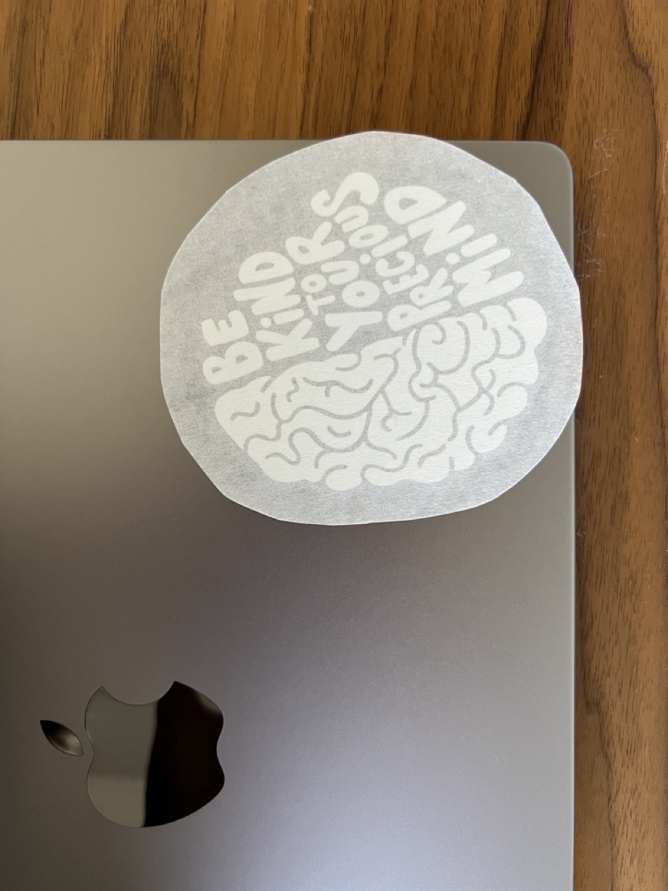
- Apply the design onto the desired surface, and carefully peel away the transfer paper to reveal the design.
- Fusion 360 construction kit
- .dxf file to laser cut your own construction kit
- .eps file to vinyl cut your own sticker
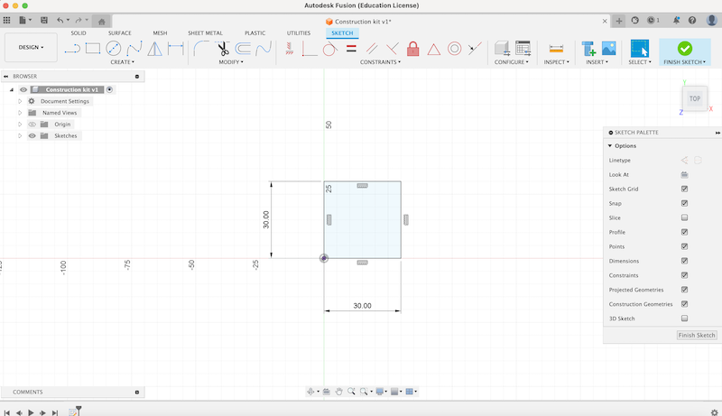
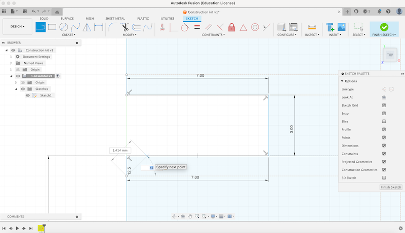
1:
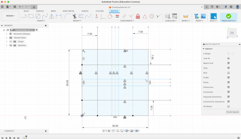
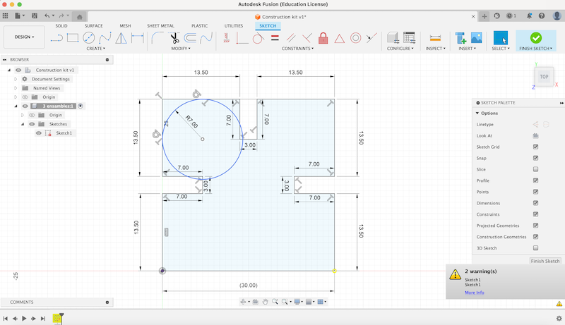
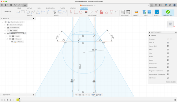
To start, I opened a new sketch on the top plane. Using the rectangle tool, I drew a 30 x 30 square and added offsets and construction lines to mark where the cuts for the joints would be.
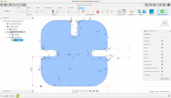
2:
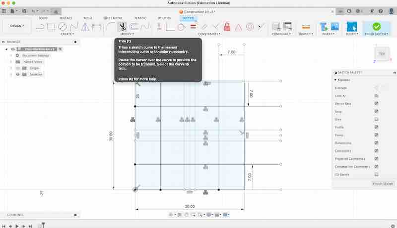
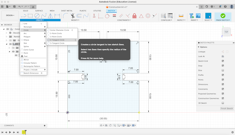
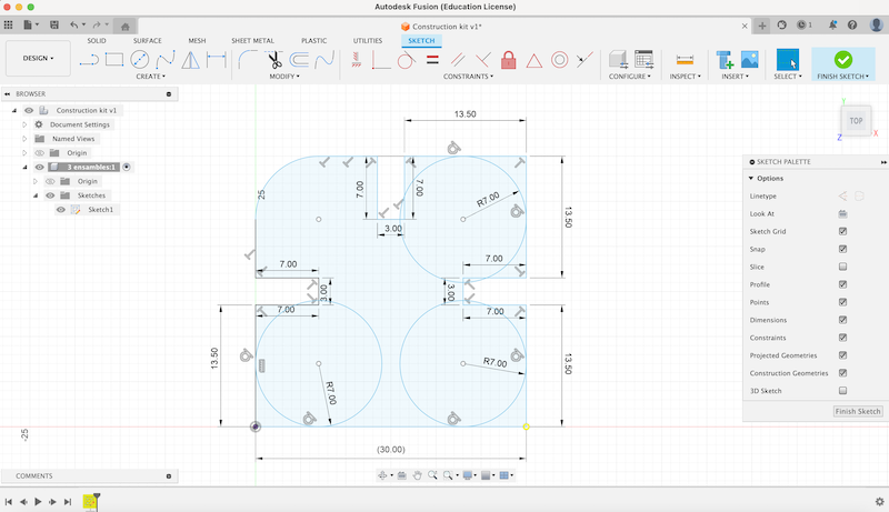
I used the trim tool to remove unnecessary lines. Next, I used the '2-Tangent circle' tool to create circles to round off the corners, and once again, I used the trim tool to refine the shape.
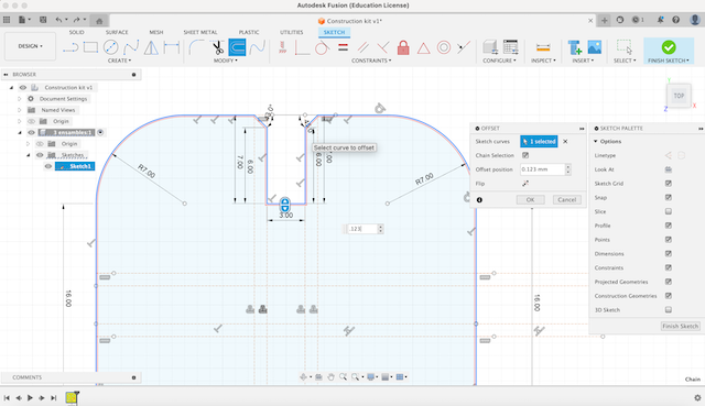
3:
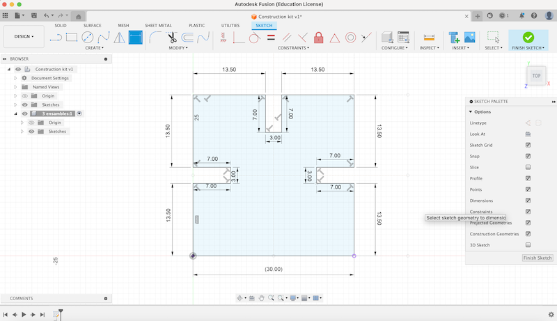
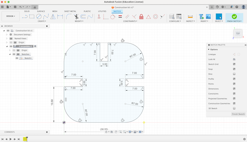
To ensure smooth joints between pieces, I created a 1 mm offset and a 45˚ line at the joint spaces.
4:
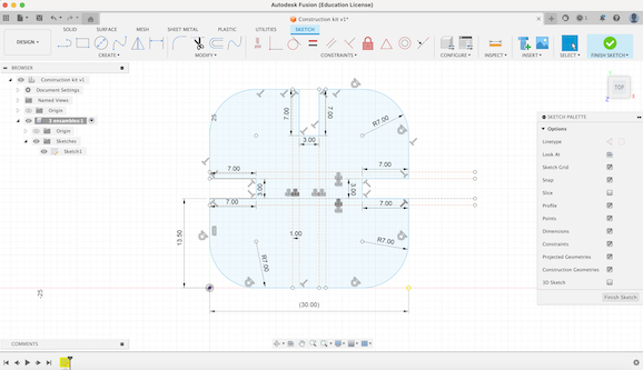
Additionally, I added a 0.123 offset to account for the kerf (the width of the laser beam). I then replicated this entire process for all the square pieces, adjusting the number of joints for each one.
5:
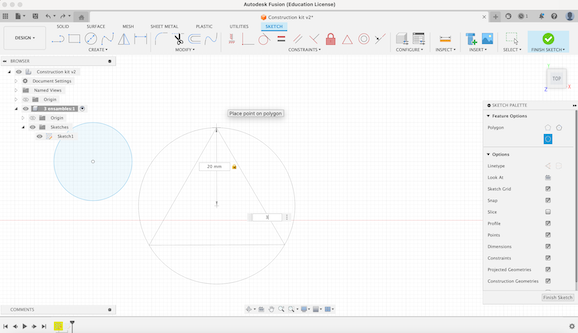
As for the circle, I simply used the circle tool to draw a 20 mm circle, as it was a straightforward piece.

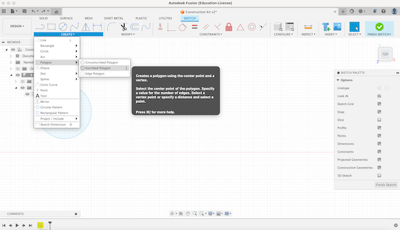
6:
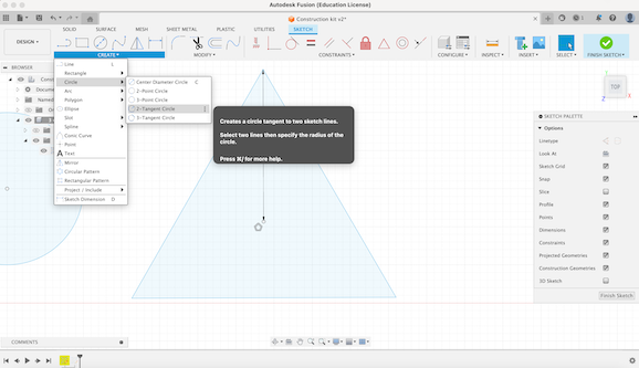
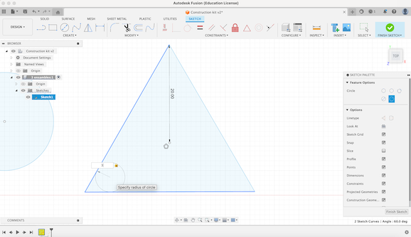
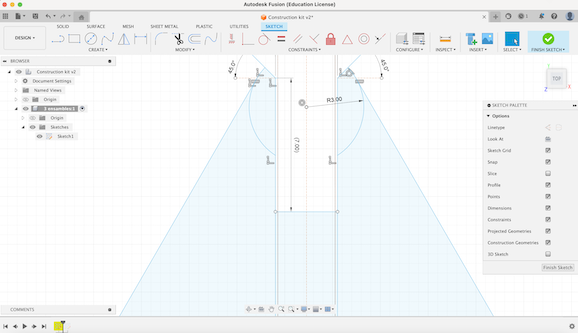
For the triangle, I followed a similar process. Under the ‘Create’ navigate to ‘Polygon’ and select ‘Inscribed Polygon’. I created a triangle with 20 mm radius. Then, to round off the corners, I used the ‘2-Tangent Circle’ tool and created 3 mm circles on each edge of the triangle.
7:
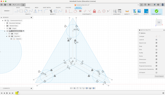
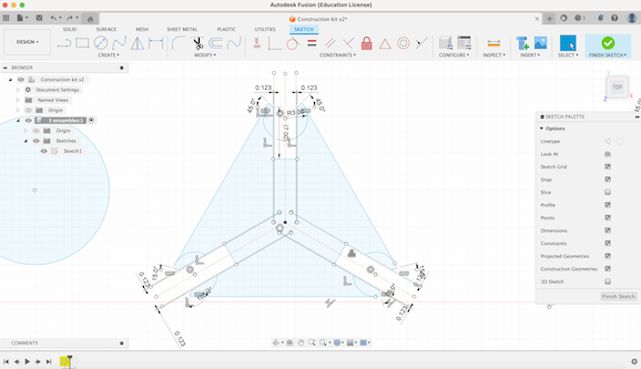
>Afterwards, I created construction lines and offseted them 3 mm, corresponding to my MDF thickness. I then created the 45˚ lines to ensure better joints between pieces. Once I had all of these measurements done, I used the trim tool to better define the outline of the piece.
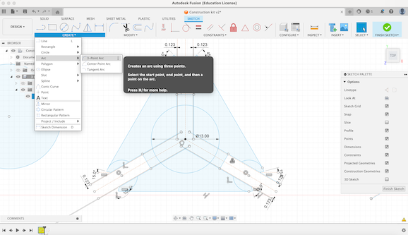
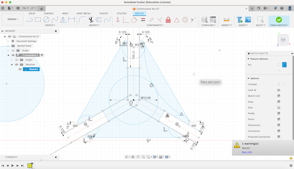
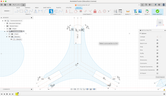
8:
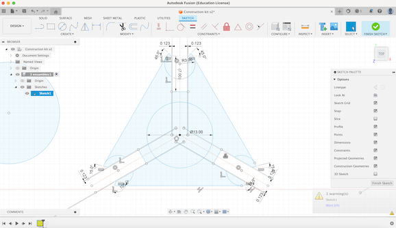
Following that I proceeded to create a circle with a diameter of 13 mm serving as a valuable reference point for the subsequent arc. Using the ‘3-Point Arc’ tool I made the necessary curvature for the triangle design. Finally, I used the trim tool to erase any traces that were no longer needed and finished the outline of the triangle.
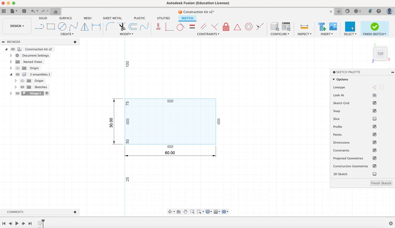
9:
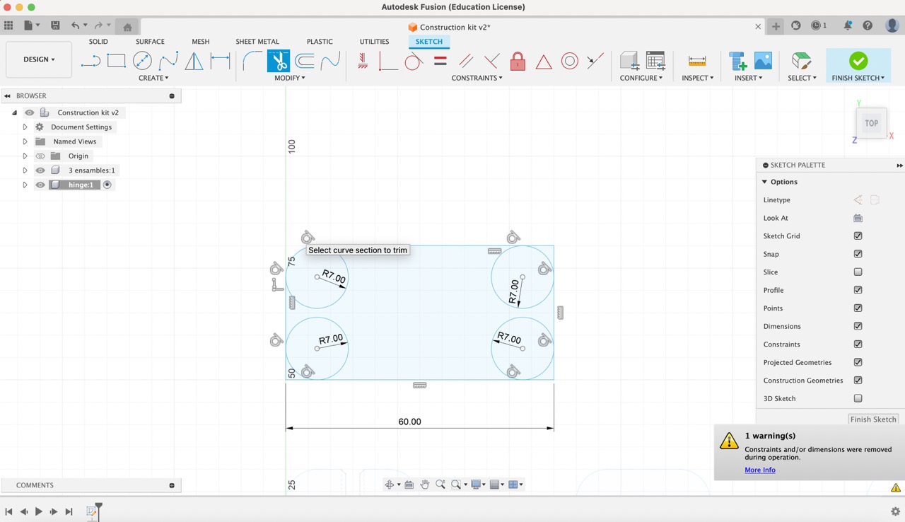
Finally for the flexible rectangle I followed the following video to create the cutting pattern. Initially, I formed a rectangle measuring 60 x 30 units. Then, I utilized the '2-Tangent Circle' tool to add R7 mm circles, rounding off the edges. Additionally, I established joints with a depth of 6 mm.
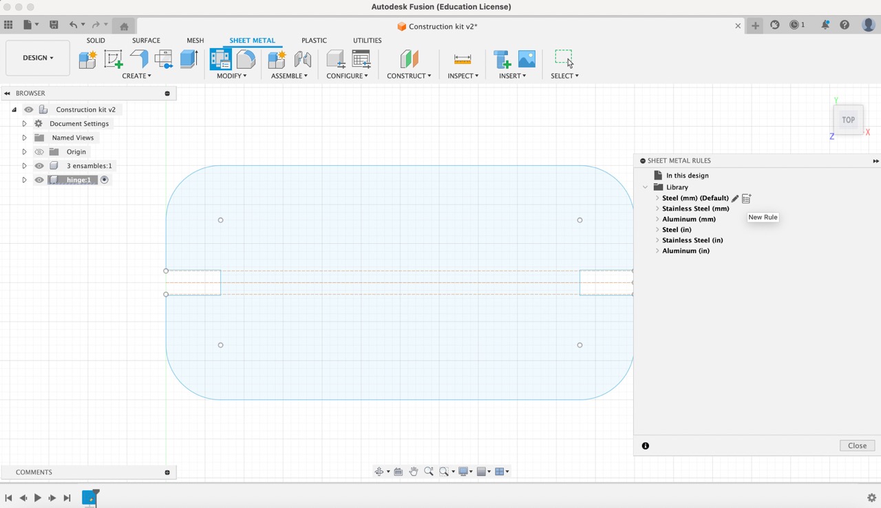
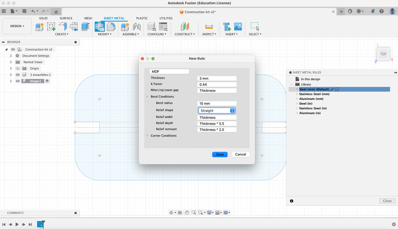
10:
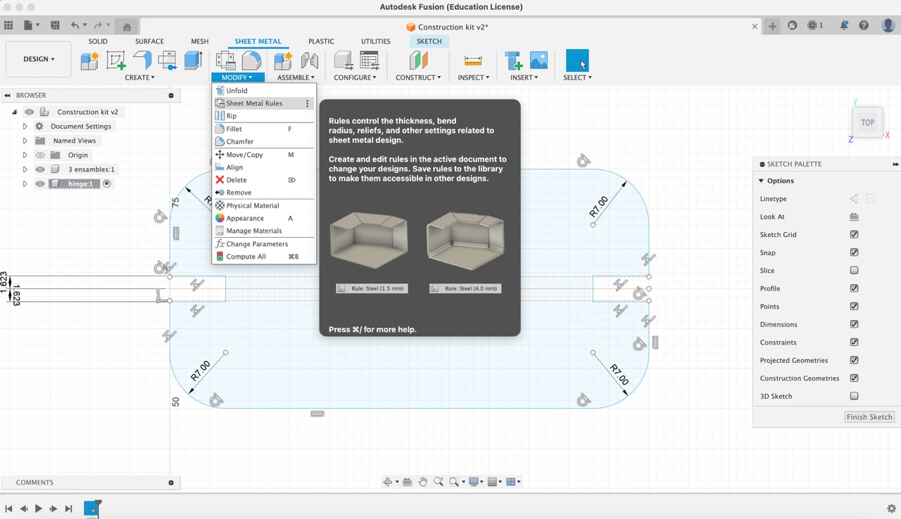
Following that, I navigated to the 'Modify' menu and selected 'Sheet metal rules'. Next to the existing rule for 'Steel (mm)' (which is the default), I created a new rule by selecting 'New Rule'. I renamed this new rule to 'MDF' and specified a thickness of 3 mm to accurately represent the material being used.
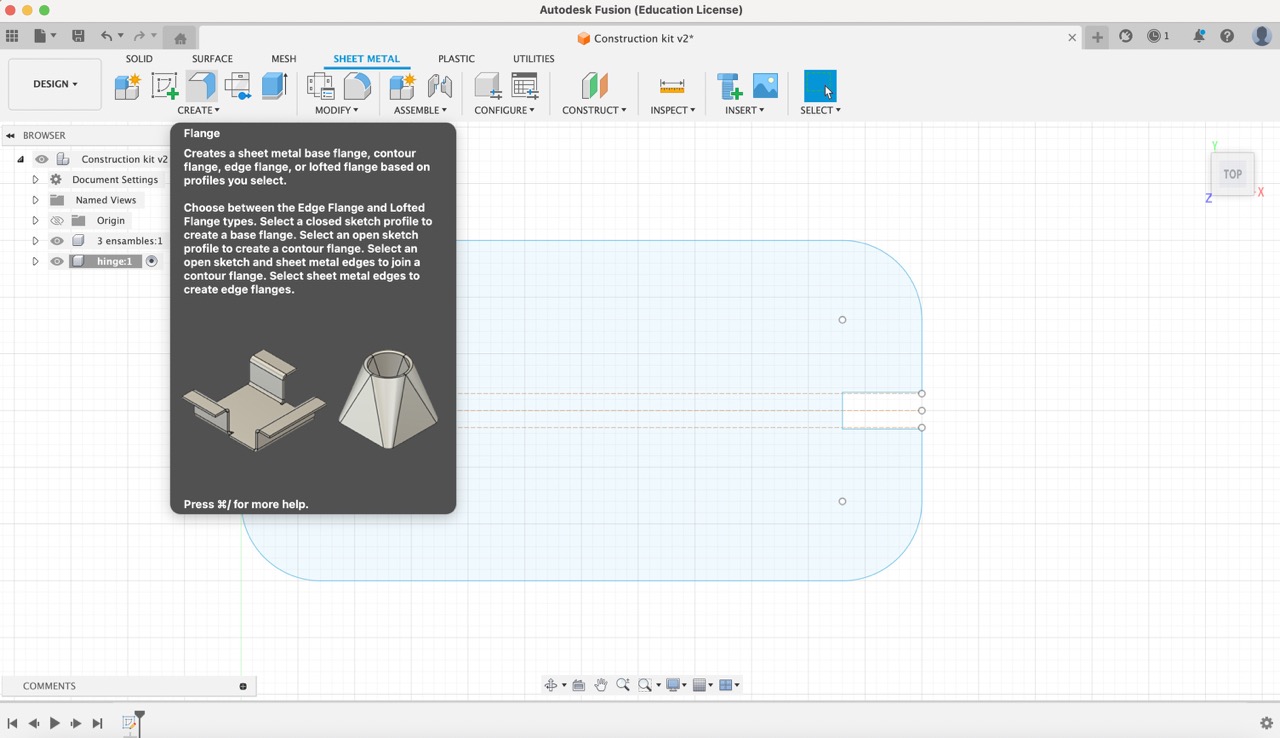
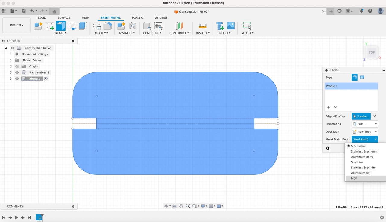
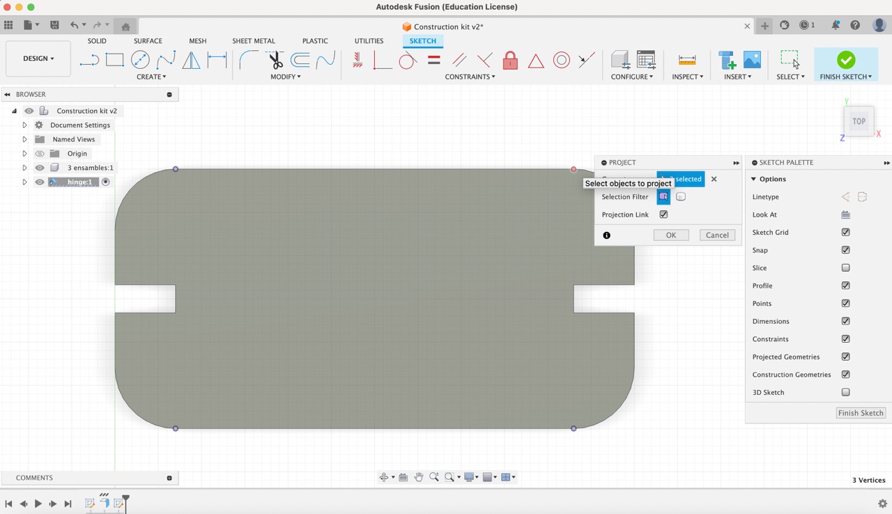
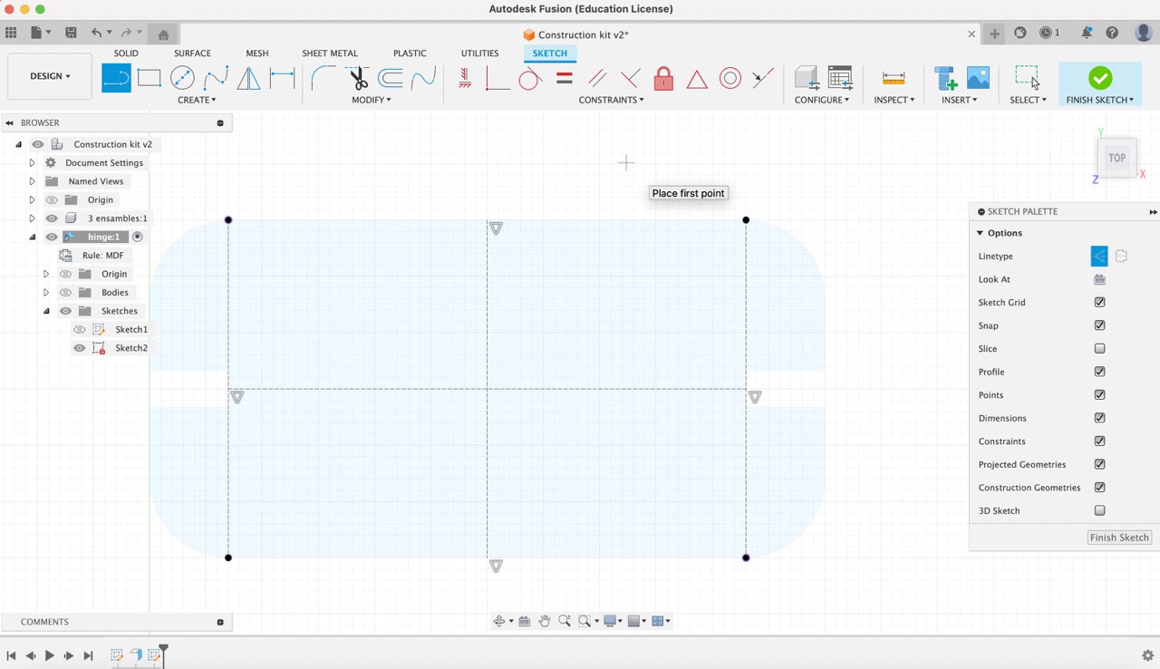
11:
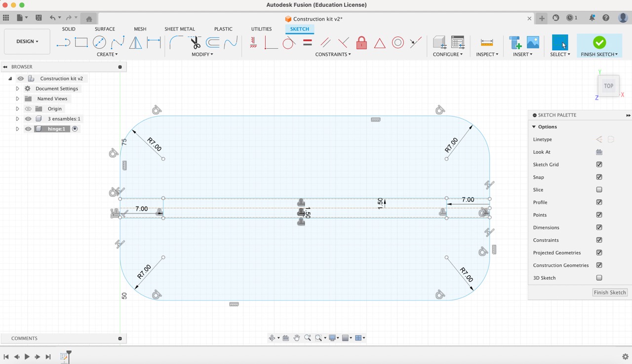
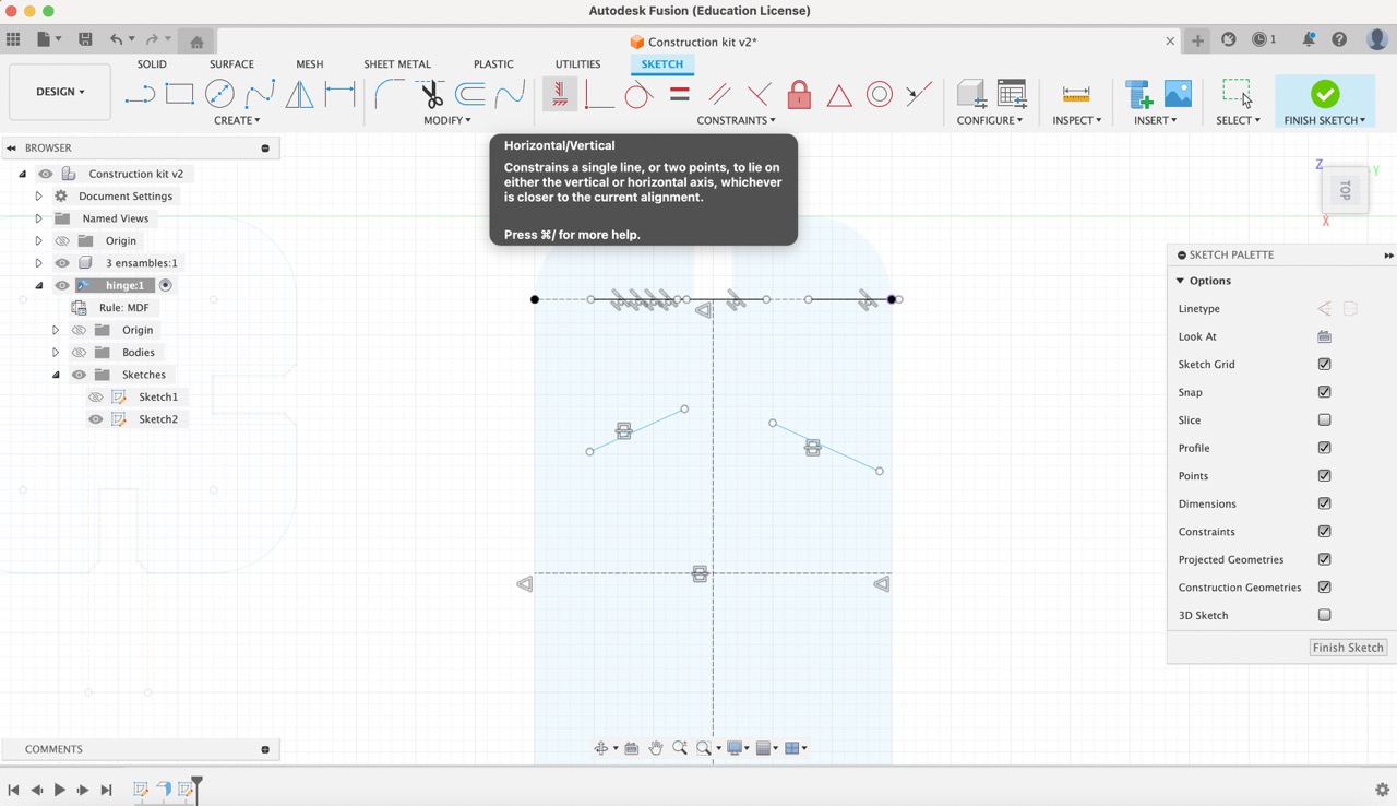
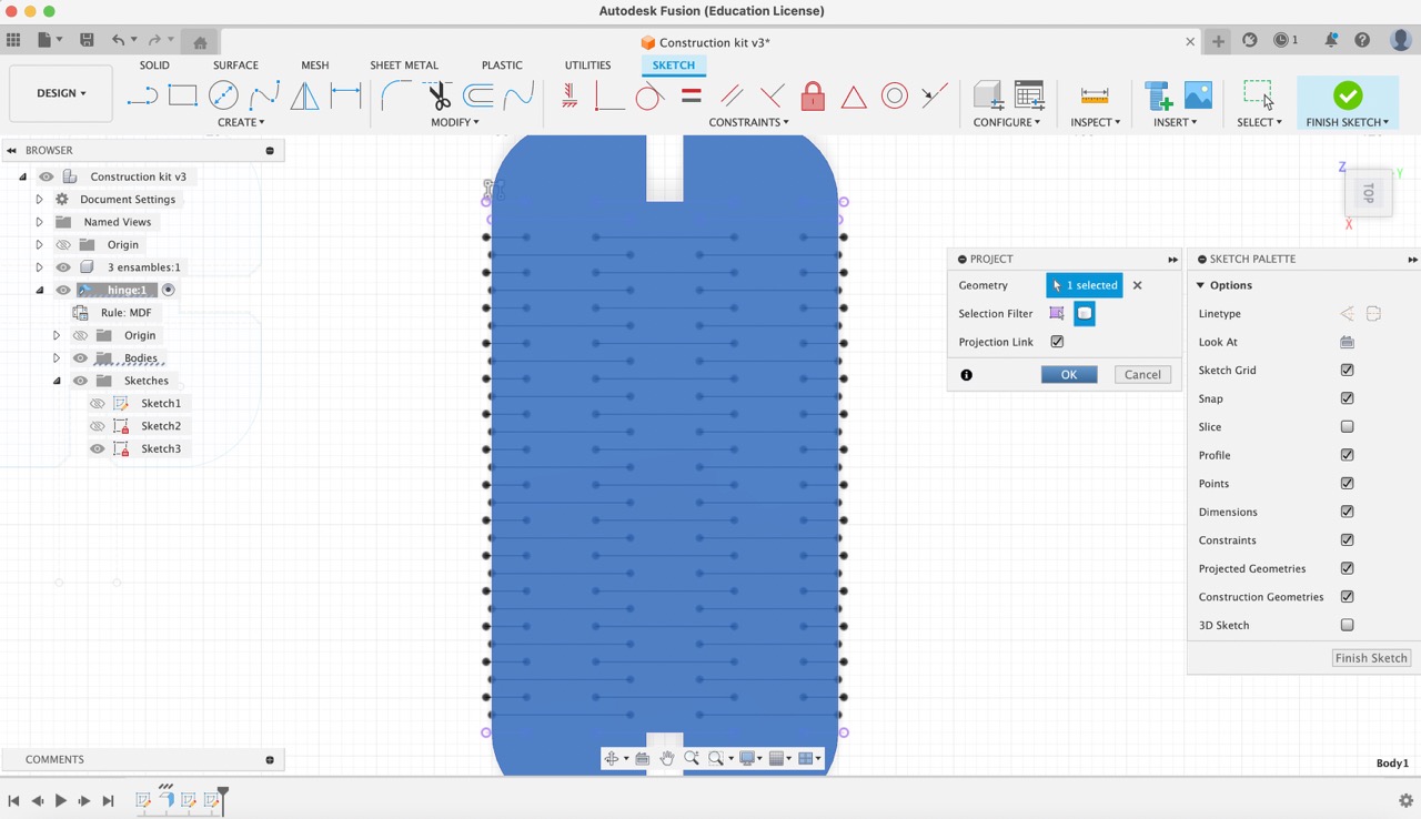
Afterward, I proceeded to select 'Create Flange' and chose the newly created 'MDF' rule under the 'Sheet metal rule' option. Using the 'Project' tool, I selected the four points on the rectangle where I intended the pattern to be applied. Subsequently, I employed the construction line tool to vertically join these projected points, while also drawing a line through the middle of the piece both vertically and horizontally.
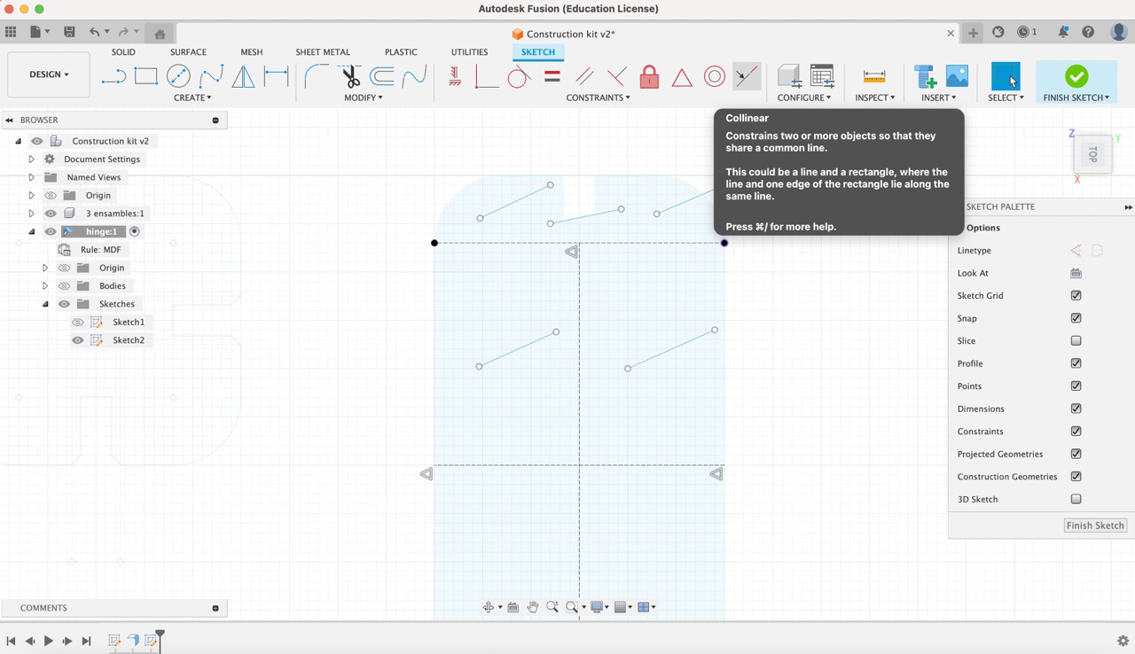
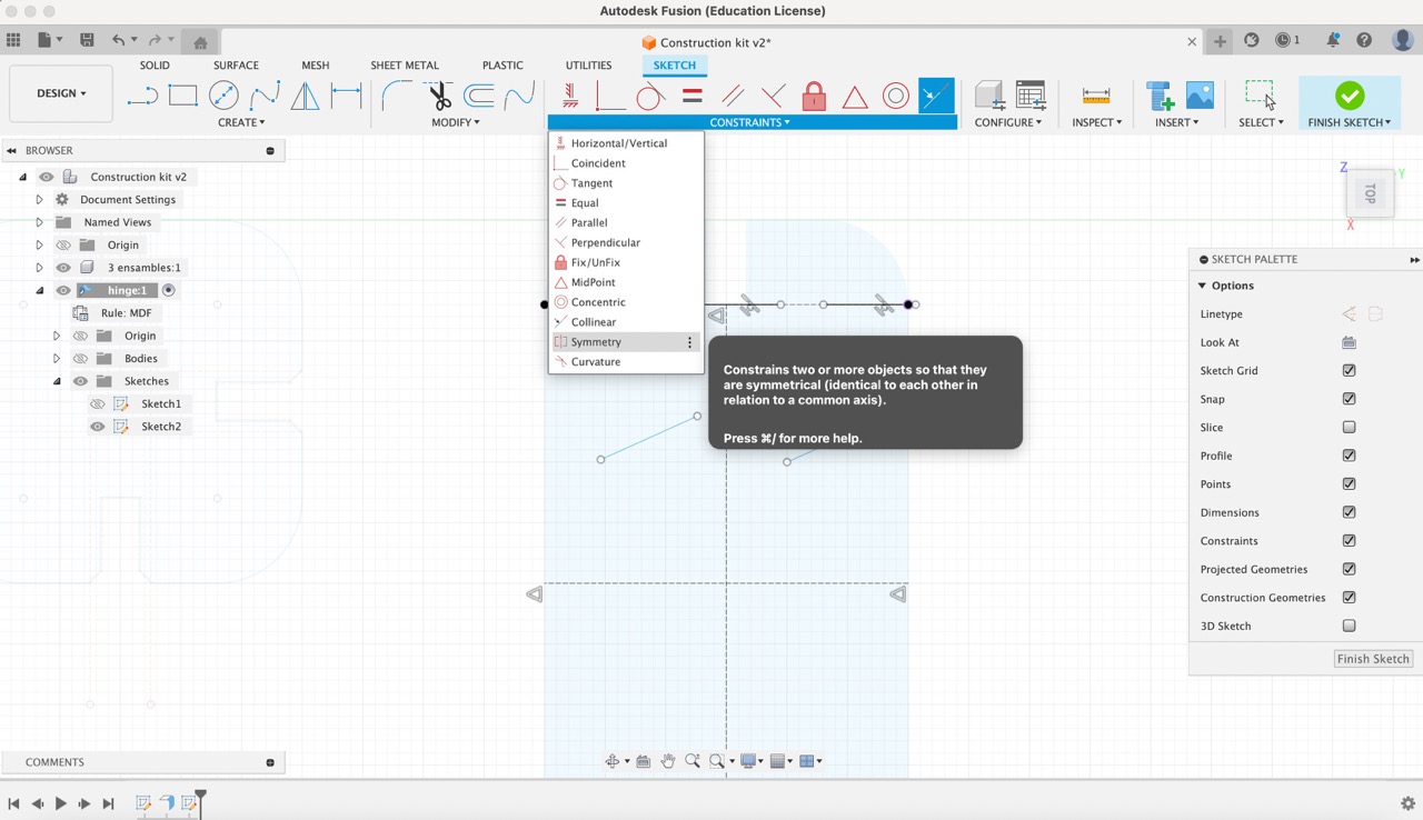
12:
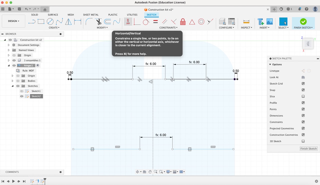
Following that, I proceeded to sketch five lines and utilized the 'Constraints' menu to adjust them accordingly. Initially, I utilized the collinear tool to ensure that the three top lines were collinear with the first horizontal construction line. Next, I applied the symmetry constraint to the two bottom lines, followed by implementing the horizontal constraint to finalize the adjustments.
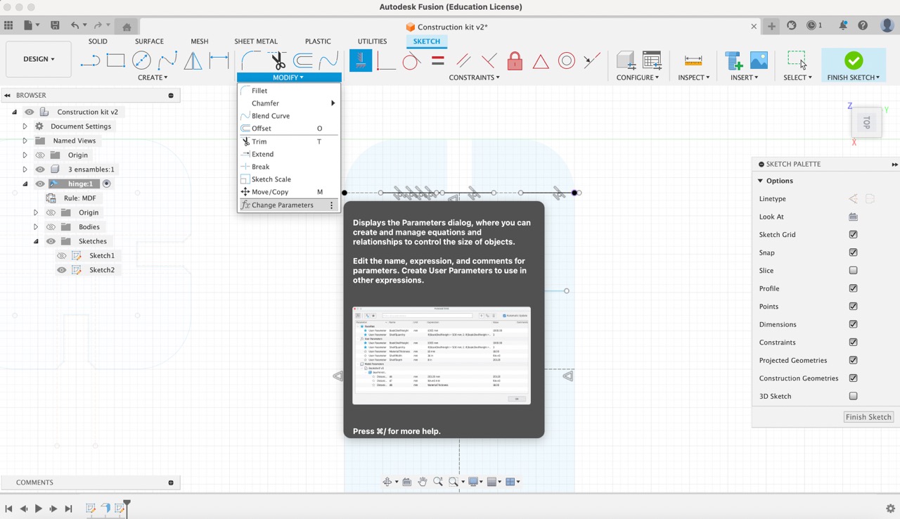
13:
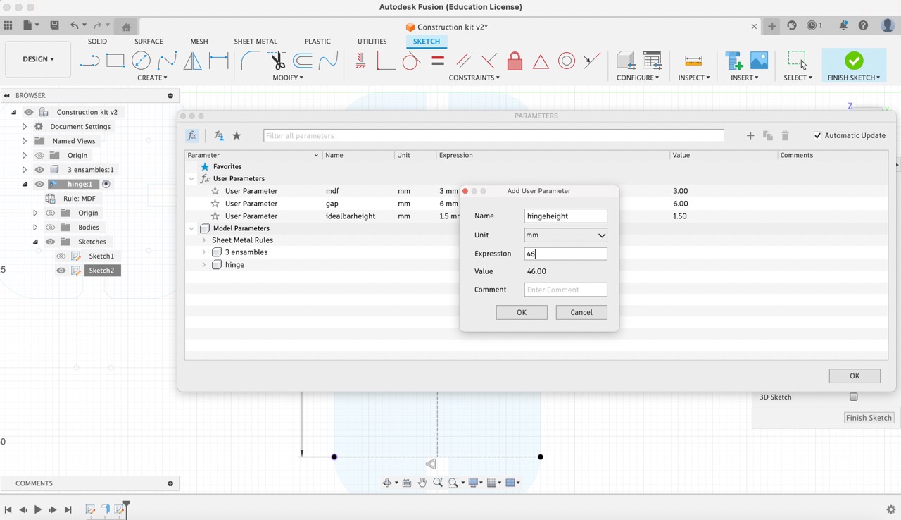
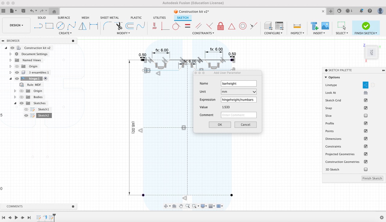
Then, I navigated to the 'Modify' menu and selected 'Change Parameters'. I then proceeded to create the following parameters:
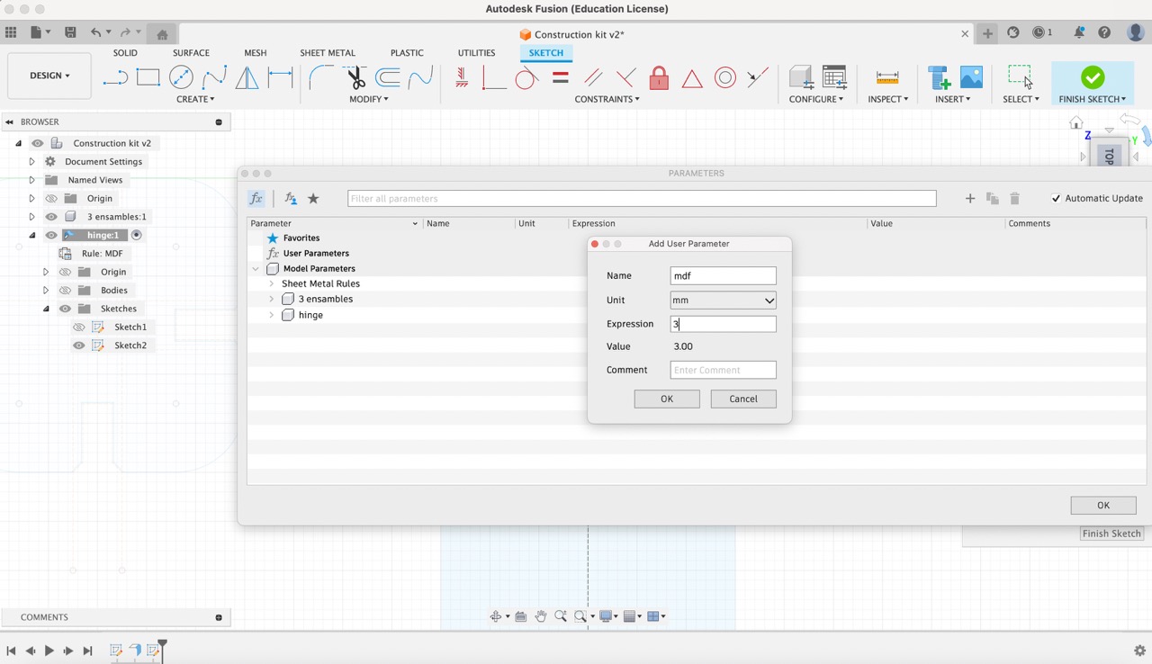
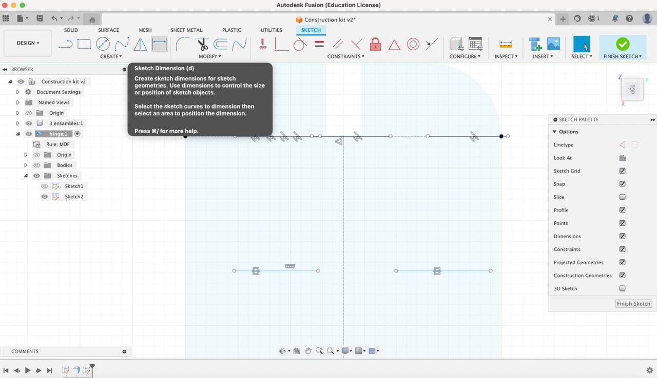
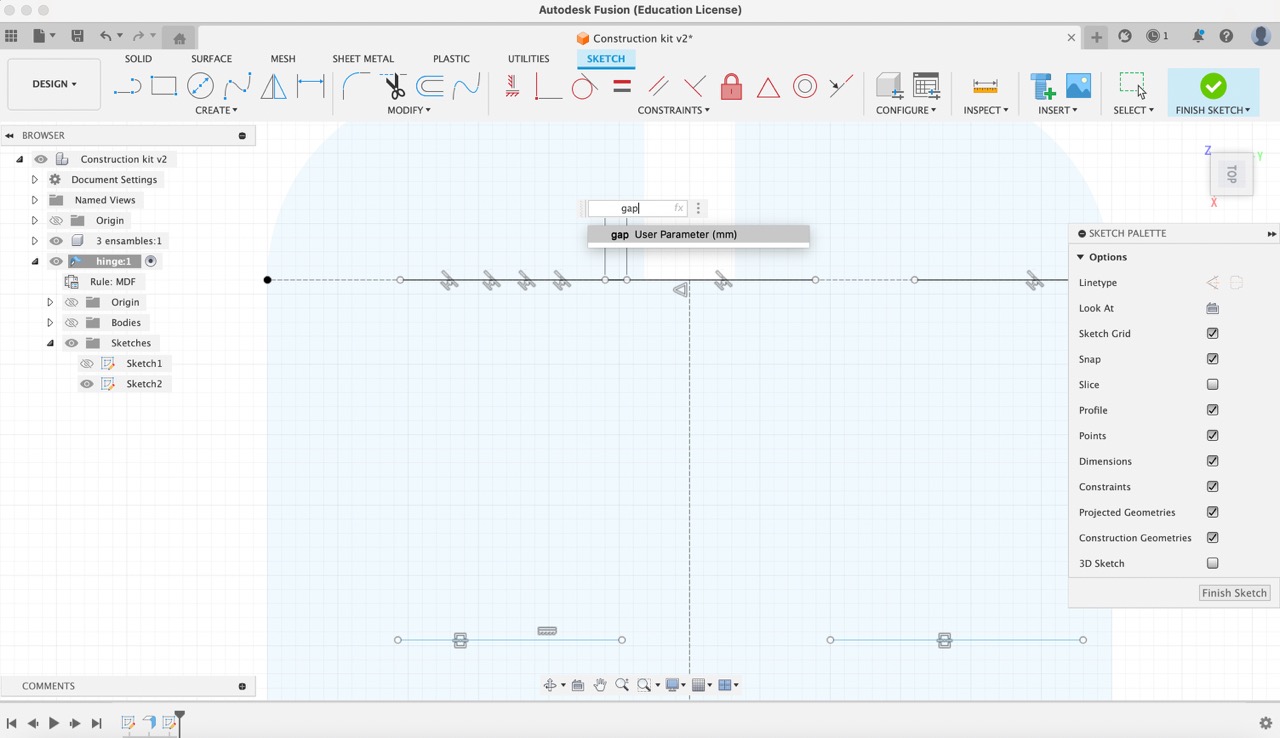
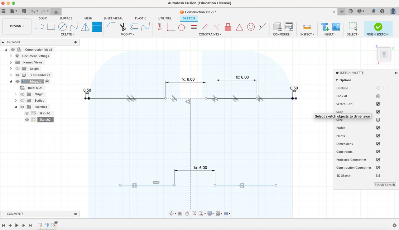
14:
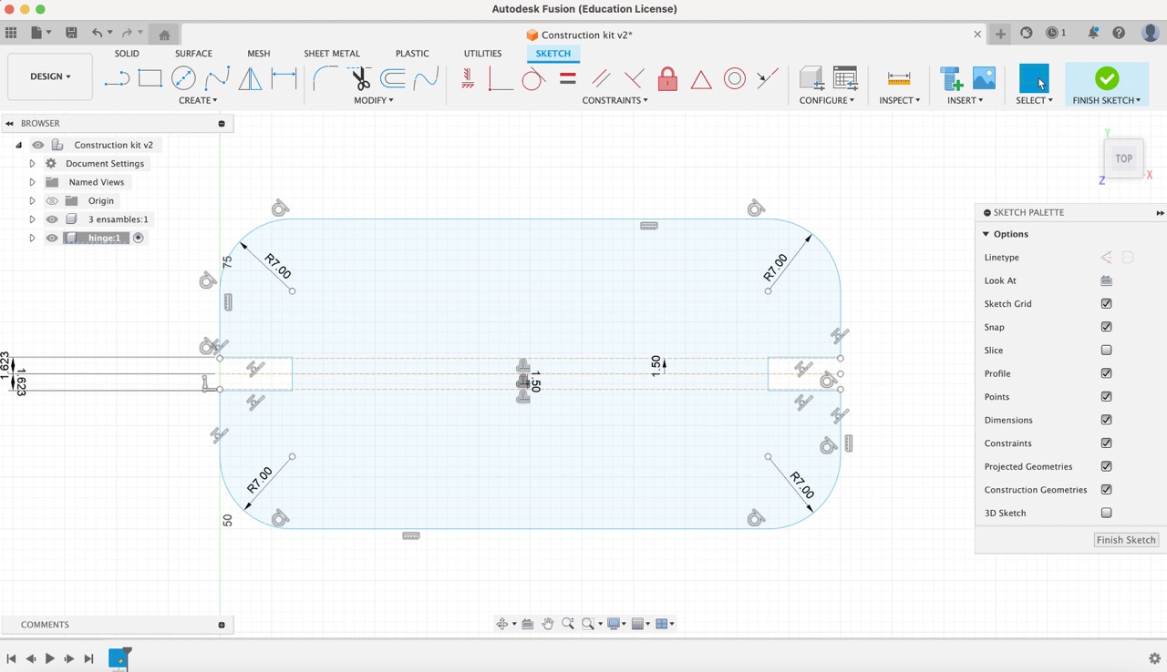
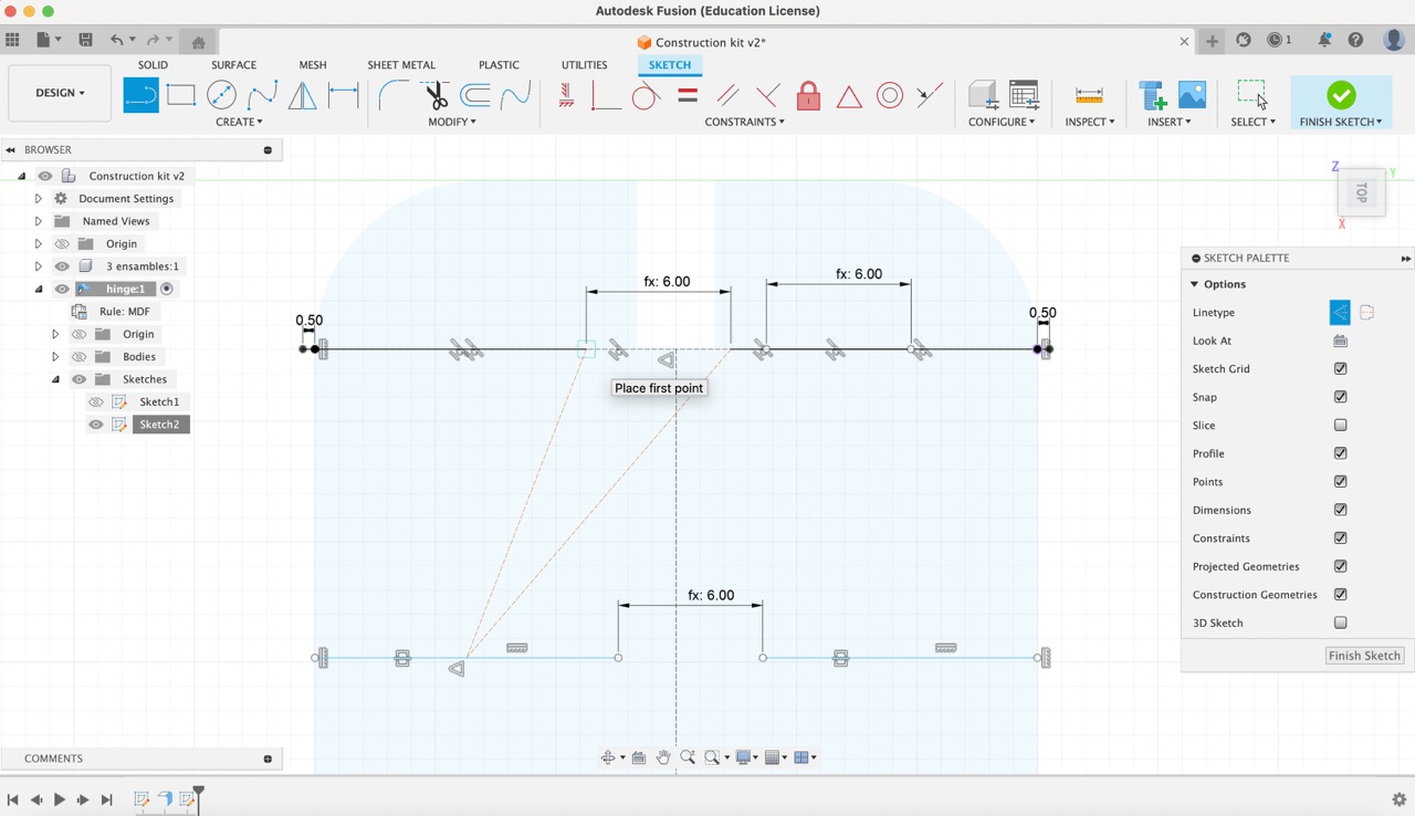
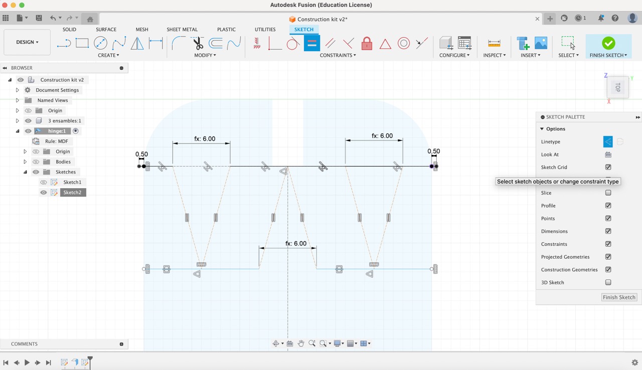
Following the parameter creation, I utilized the sketch dimension tool to add the gap parameter between each line endpoint. Additionally, I applied a 0.5 mm dimension to the top lines. Subsequently, I adjusted the endpoints of the bottom lines, moving them closer to the outer outline of the rectangle. To ensure alignment, I added a vertical constraint between the bottom edge points and the top edge points.
15:
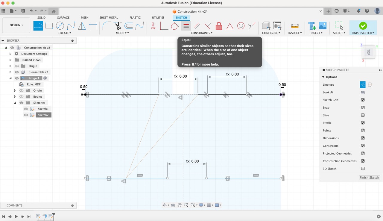
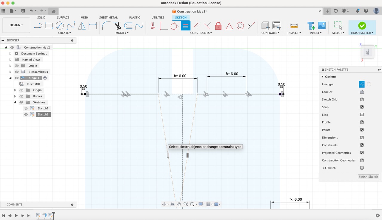
Then, I generated construction lines connecting the endpoints of the top lines with the midpoint of the first bottom line. Subsequently, I applied the equal constraint to ensure both of these lines were of equal length. I then repeated the same procedure with the remaining endpoints and midpoints.
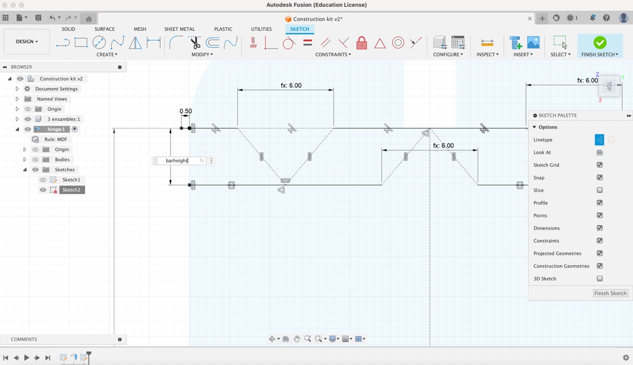
16:
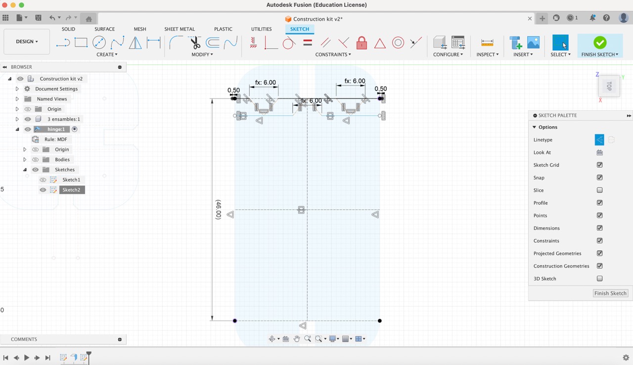
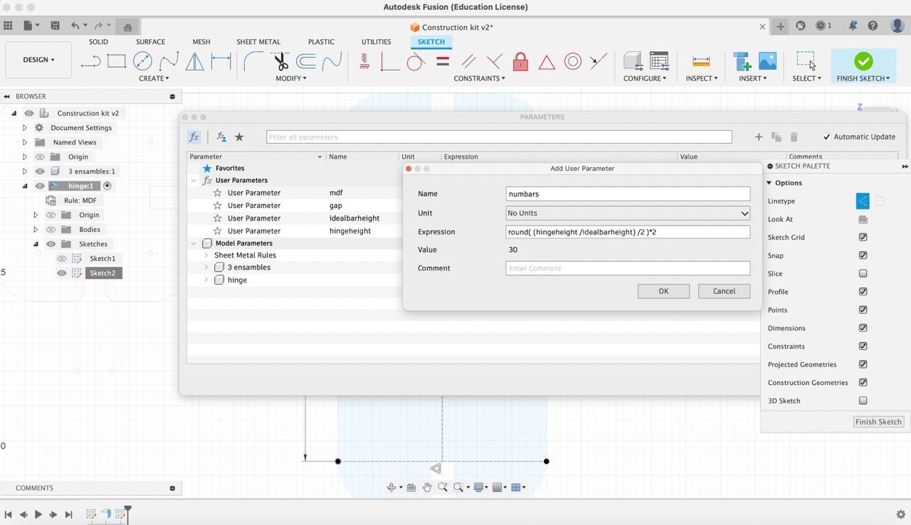
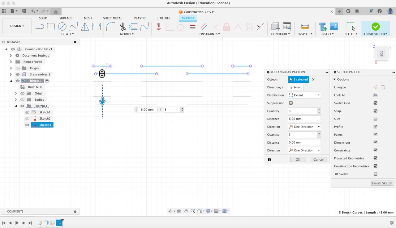
Following those steps, I utilized the dimension tool to measure the total height of the design. Subsequently, I created a new parameter named 'HingeHeight' with a value of 46 mm. Then, using the expression: round((HingeHeight/IdealBarHeight)/2)*2, I established a parameter to determine the number of bars required. Finally, I added another parameter for 'BarHeight' using the expression: HingeHeight/NumBars. Using the dimension tool, I inserted the 'BarHeight' parameter between the top and bottom lines. Additionally, I mirrored the top lines to the bottom of the rectangle pattern line.
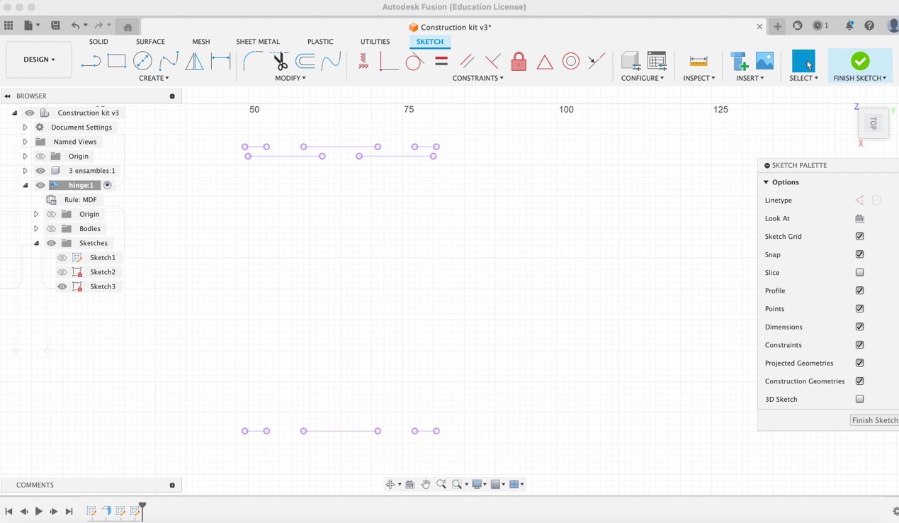
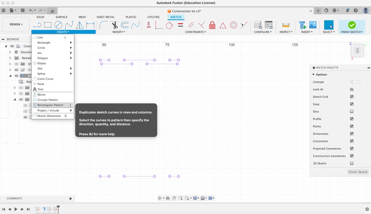
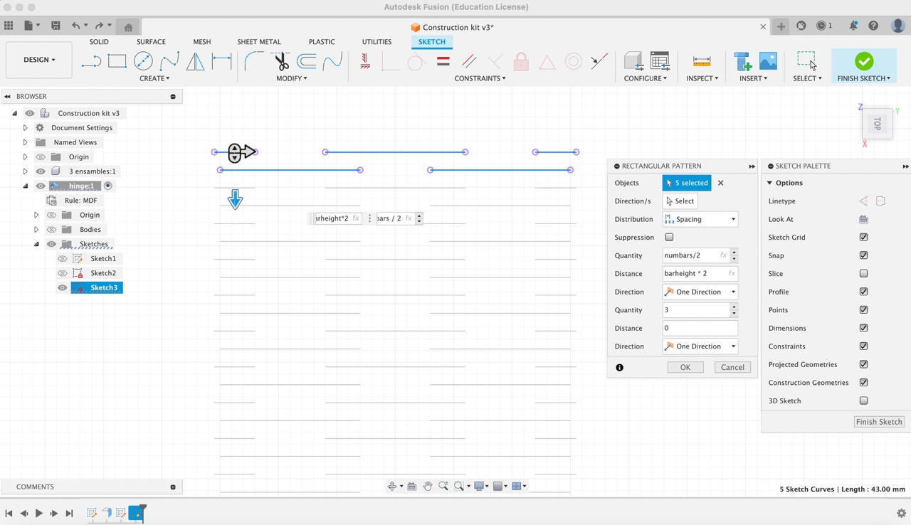
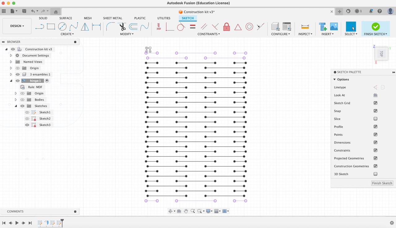
17:
Next, using the 'Project' tool, I selected the lines that were created. Then, under the 'Create' menu, I chose 'Rectangular pattern'. I selected the top two rows and set the quantity to 'NumBars/2'. For the distance, I specified 'BarHeight*2'. This configuration ensures that the bars are evenly distributed with the specified height between them, creating the desired pattern.
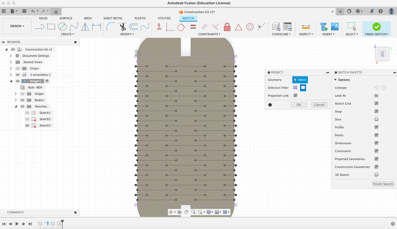
18:
Finally, I projected the lines created onto the body of the rectangle.
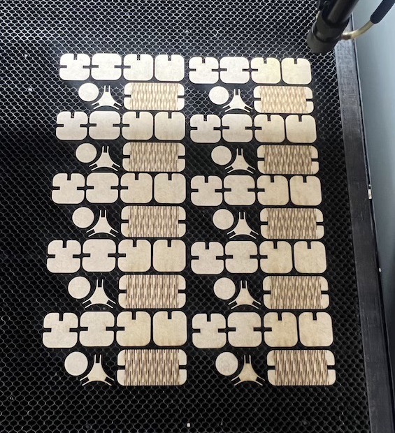
Cutting
Problems while cutting
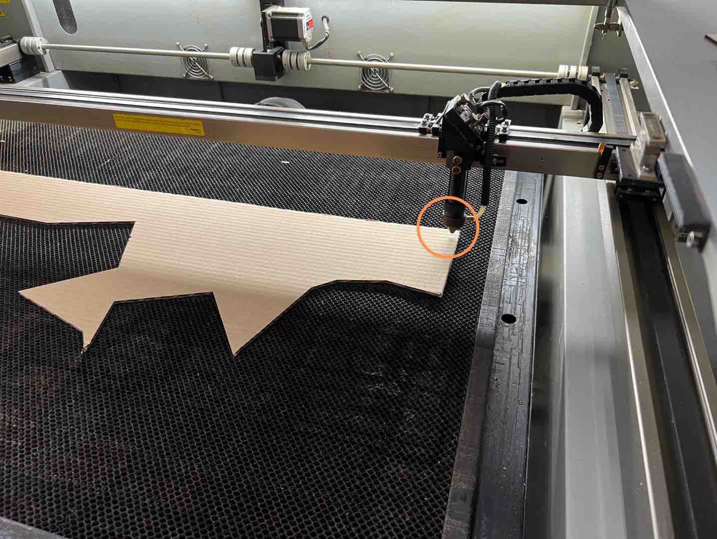
The laser cutter that I was using is slightly descalibrated, given that the cutting bed is slightly rotated, so after the first round of cutting was finished only some pieces were cut so I had to restart the cutting process once more.
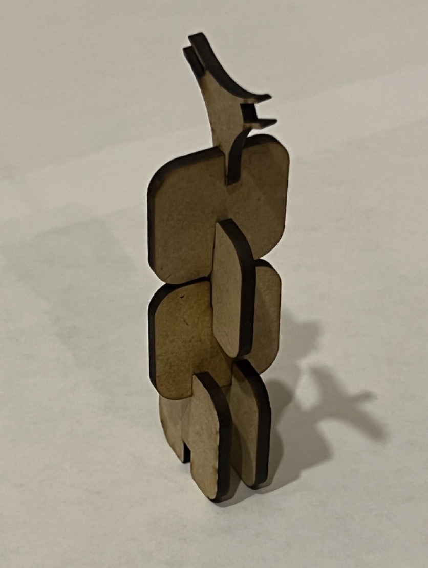
The following pictures show the proces while cutting first pieces and some assembled structures:

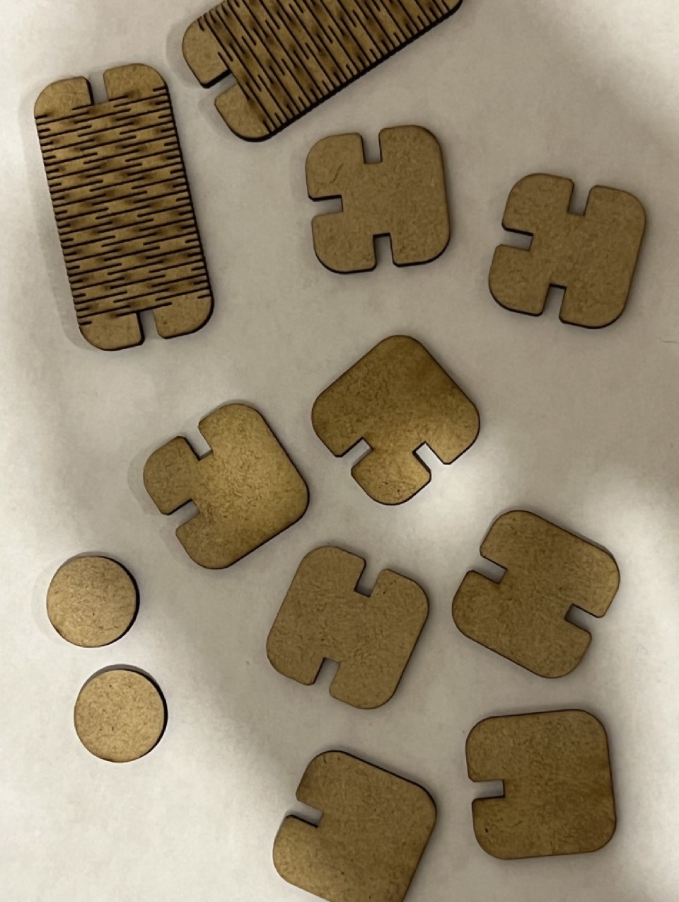
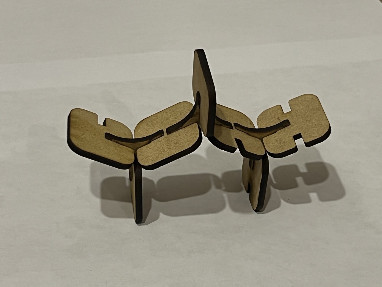
Modifications needed:
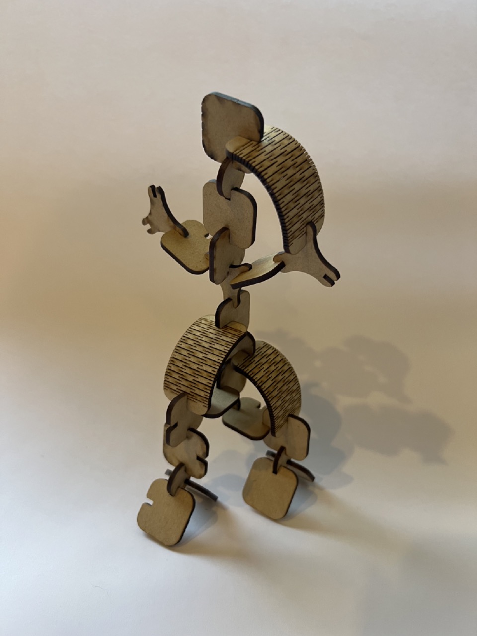
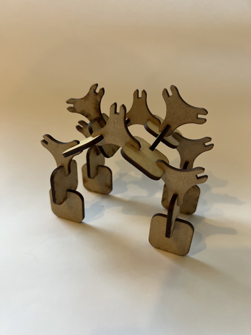
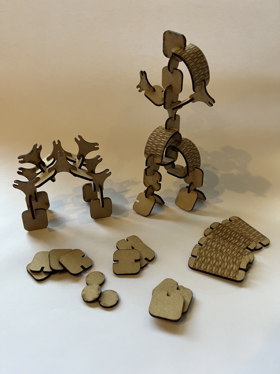
Final result
I made adjustments to the file based on feedback from the previous pieces. Afterward, I laser cut the new pieces and assembled various structures while experimenting with the construction kit.
Conclusions:
I really enjoyed this assignment and have some ideas for improving my kit. I would definitely extend the length of the flexible rectangles and perhaps create triangles with deeper joints to mimic the pieces from the initial attempt. Although the triangles were quite thin, the structures looked good. I could explore or recreate a new triangle piece with these characteristics without it being too fragile.
Vinyl Cut
Making the design
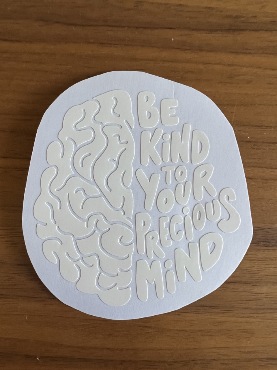
I wanted to recreate this sticker for my computer.
Vinyl Cutting
Transfer the design