2. computer aided design
During the second week, I focused on creating both a 2D design using Adobe Illustrator and a 3D model using Fusion 360. I have a strong background in Illustrator, having used it throughout my career. However, this was my first experience with modeling in Fusion 360. While I typically use Rhino for modeling, I decided to explore Fusion 360 for this project to broaden my skills and knowledge in 3D modeling.
2D design - adobe illustrator
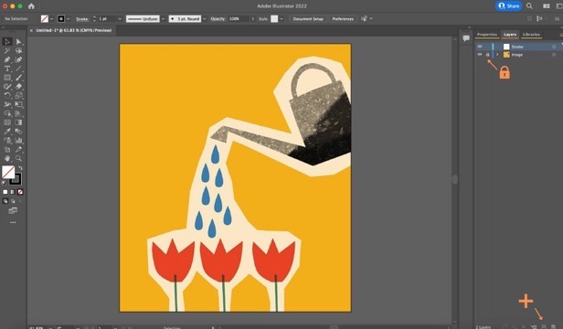
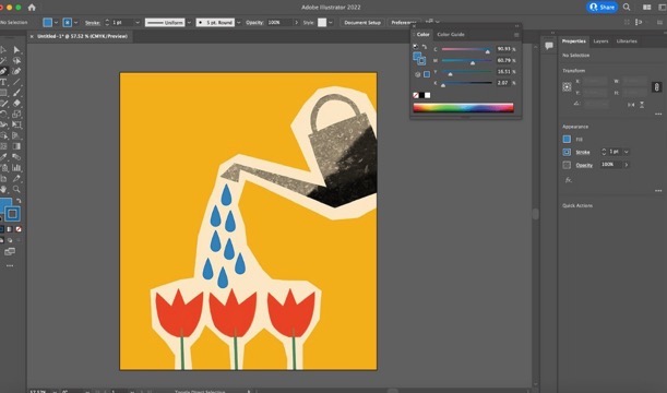
- To start, I inserted the picture I chose from Pinterest by simply dragging and dropping the image onto the artboard. On the right side, there are different panels: properties, layers, and libraries. Layers are essential for keeping everything organized, especially in complex files. So, I began by renaming the first layer to 'Image' and then locked it to prevent it from moving. Next, I created a second layer called 'Stroke'.
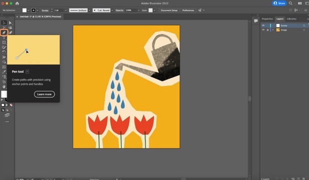
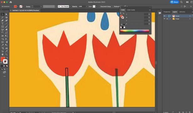
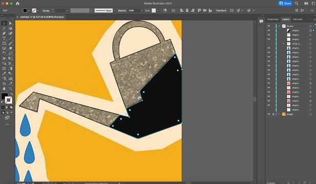
- To begin tracing the image, I selected the pen tool. This tool creates straight lines with continuous clicks. If you want to create curves, you have to keep the mouse pressed, click a final point and move your cursor until you get the desired curve.
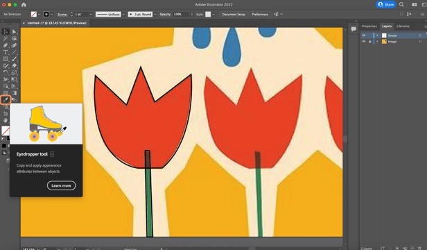
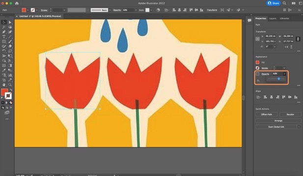
- Once the outlines of the first two shapes were done, I selected the 'eyedropper tool', which copies the color that you want. In this case, there is transparency between the two elements, so to achieve this, I adjusted the opacity in the properties panel on the right side.
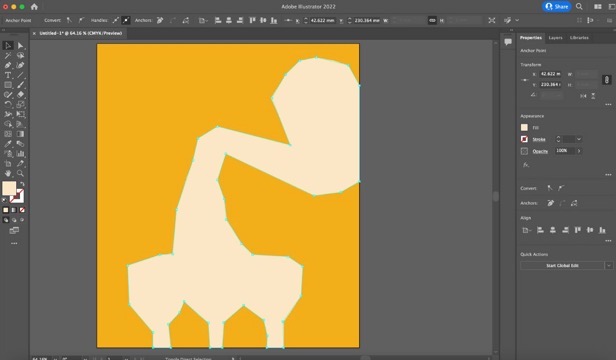
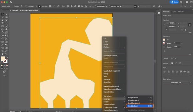
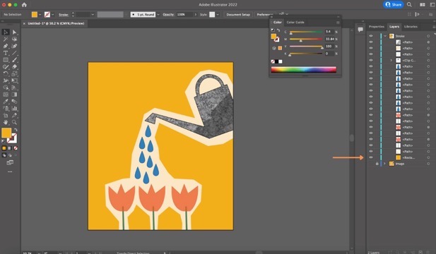
- Moving on, I traced the white element and once again used the eyedropper tool to copy the color. To ensure this element didn't block my view, I sent it to the back by right-clicking, selecting 'arrange' and then 'send to back'.
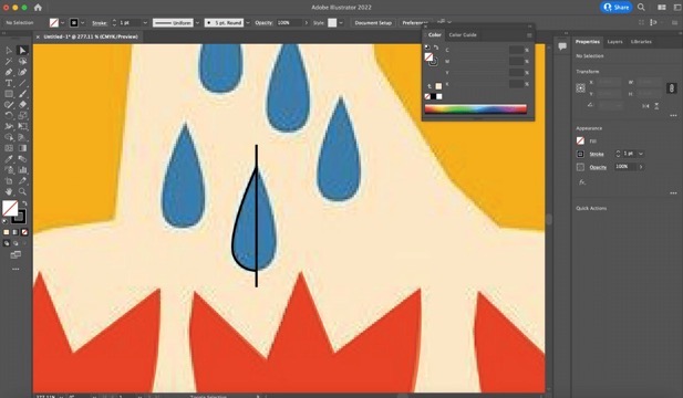
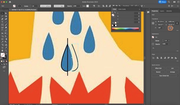
- Next, I continued with the drops. To make them symmetrical, I first traced a straight line through the middle, and then traced the outline of the drop. I copied and pasted this outline, flipped it horizontally in the properties panel, aligned the two strokes, and joined them using the 'join' command (command J).
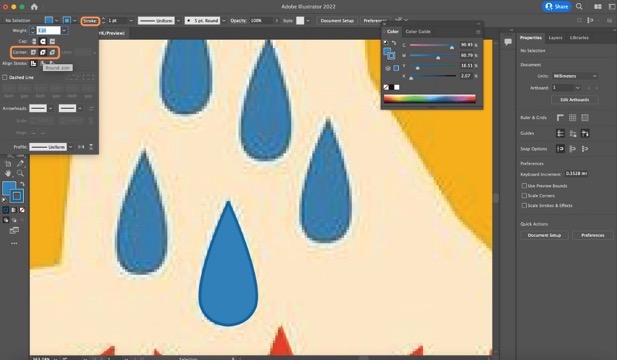
- I used the eyedropper tool for the fill color and added a stroke. To avoid sharp edges, I selected 'round corner' in the stroke panel. I then copied and pasted all of the drops.
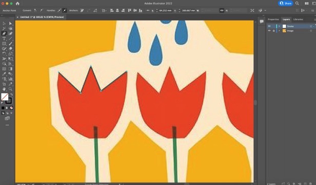
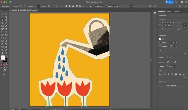
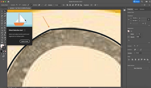
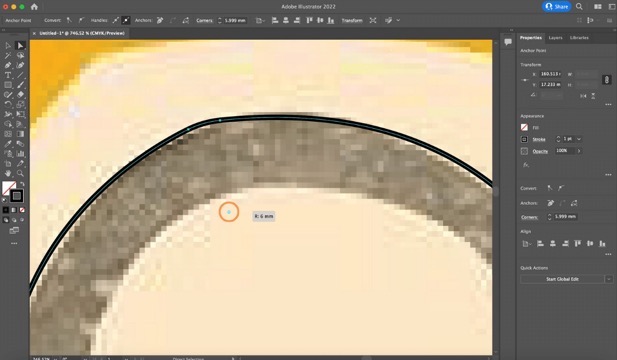
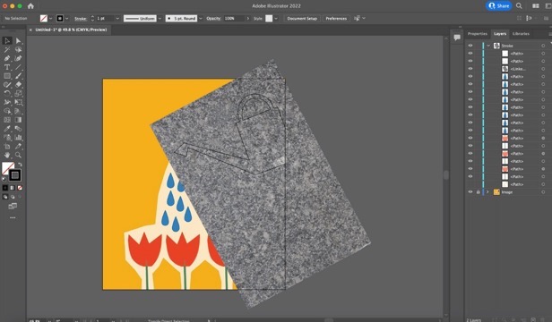
- After this, I traced the watering can. To fix a little sharp edge at the top, I selected the direct selection tool, which allows you to edit through the handles or sometimes a little circle that rounds and softens the curve.
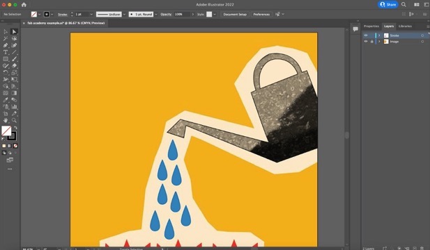
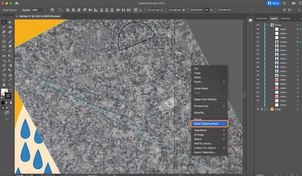
- To add texture to the watering can, I downloaded an image and added it. I made sure the trace was on top of the image, right-clicked, and selected 'make clipping mask'.
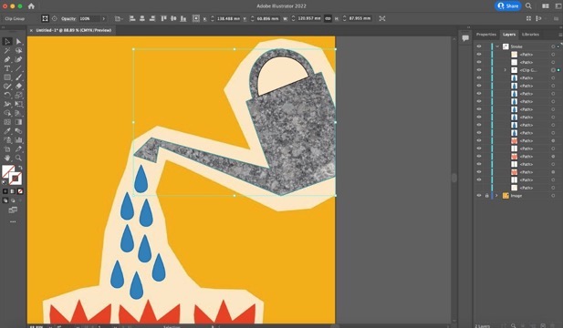
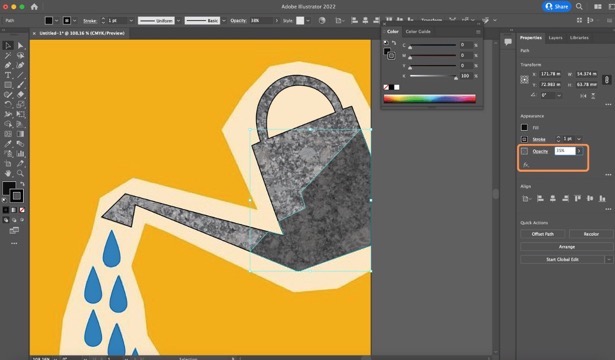
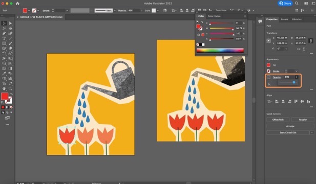
- For the shadow, I traced the outline, gave it a black color, and lowered the opacity.
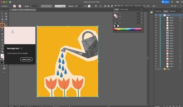
- Finally, I traced a rectangle with the rectangle tool, gave it a yellow color, and sent it to the back of the artboard.
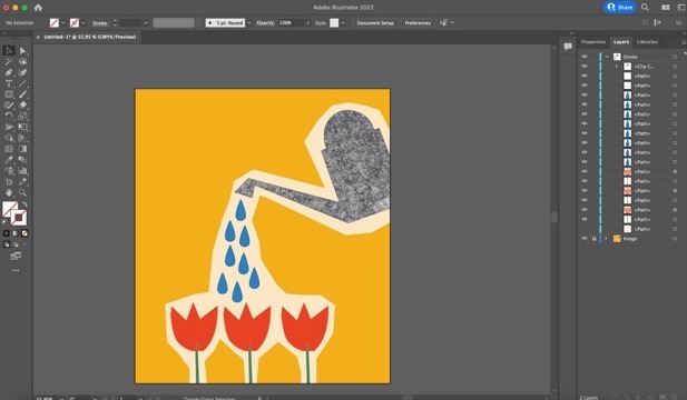
- After comparing both images, I noticed that the opacity was very low, so I adjusted the value.
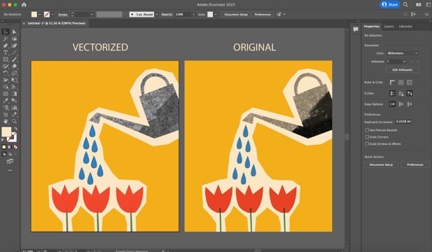
- Done! Here you can see the final result compared to the original image.

2D design - Gimp
I decided to experiment with raster graphics software. Adobe Illustrator, a vector graphics software, is ideal for maintaining quality at any size. In contrast, GIMP uses raster graphics, which are composed of pixels, making it ideal for photo editing and creating detailed images.
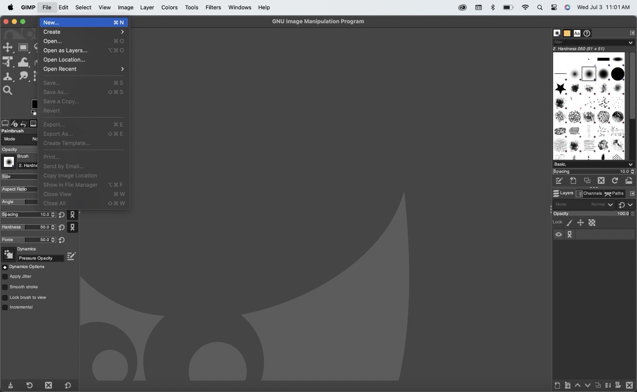
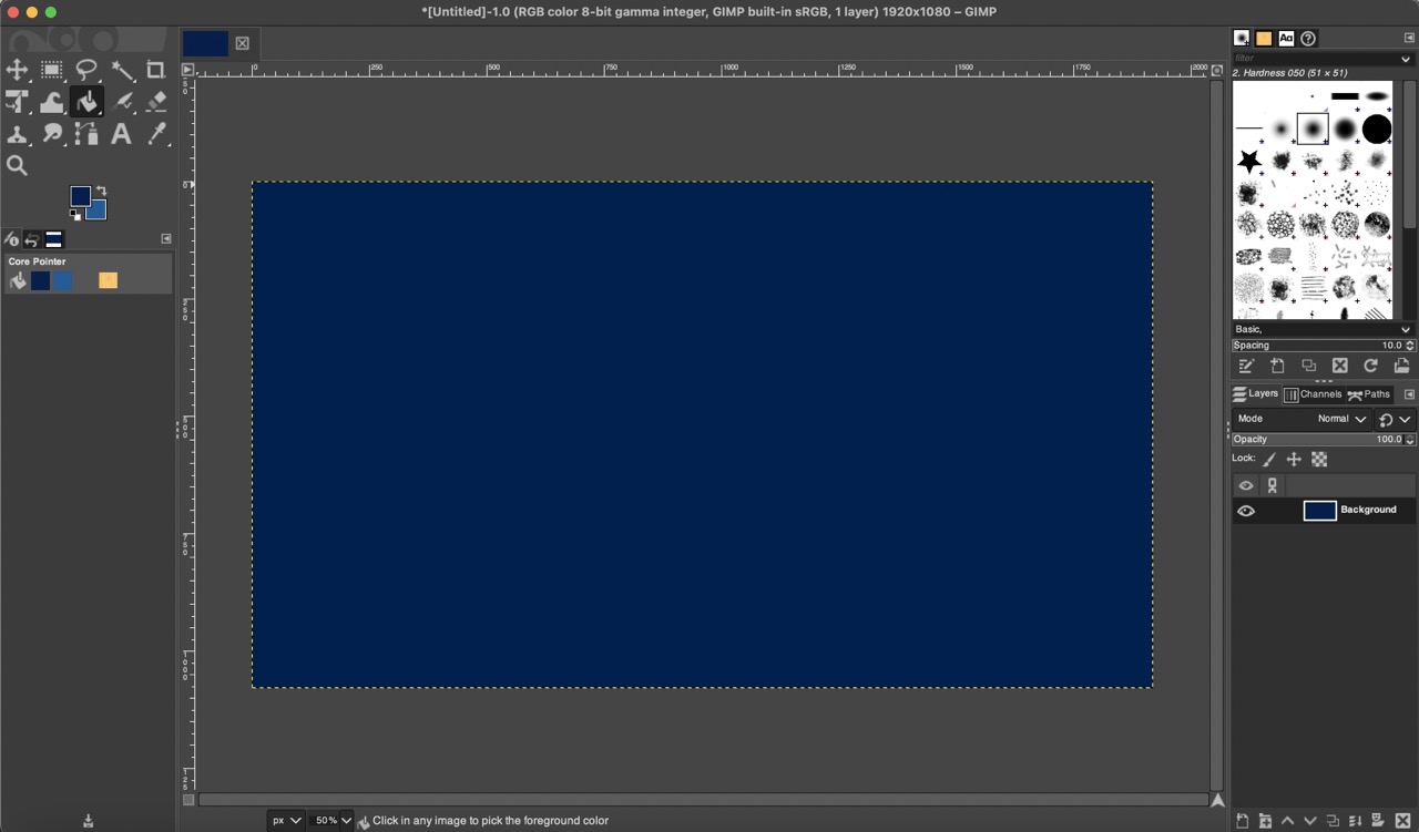
To start, I opened GIMP and created a new document from the "File" menu.
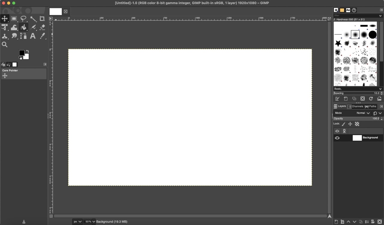
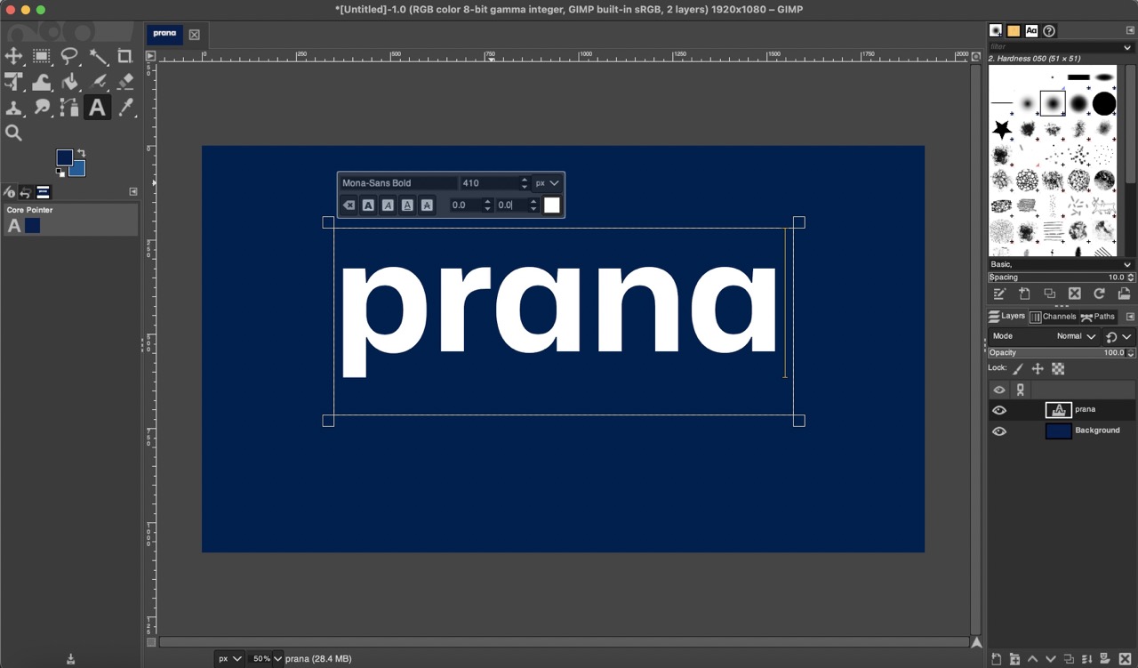
I used the "Bucket Fill Tool" to fill the white canvas with my selected background color. Next, I used the "Text Tool" to write "prana" and adjusted the text size to 410 pixels.
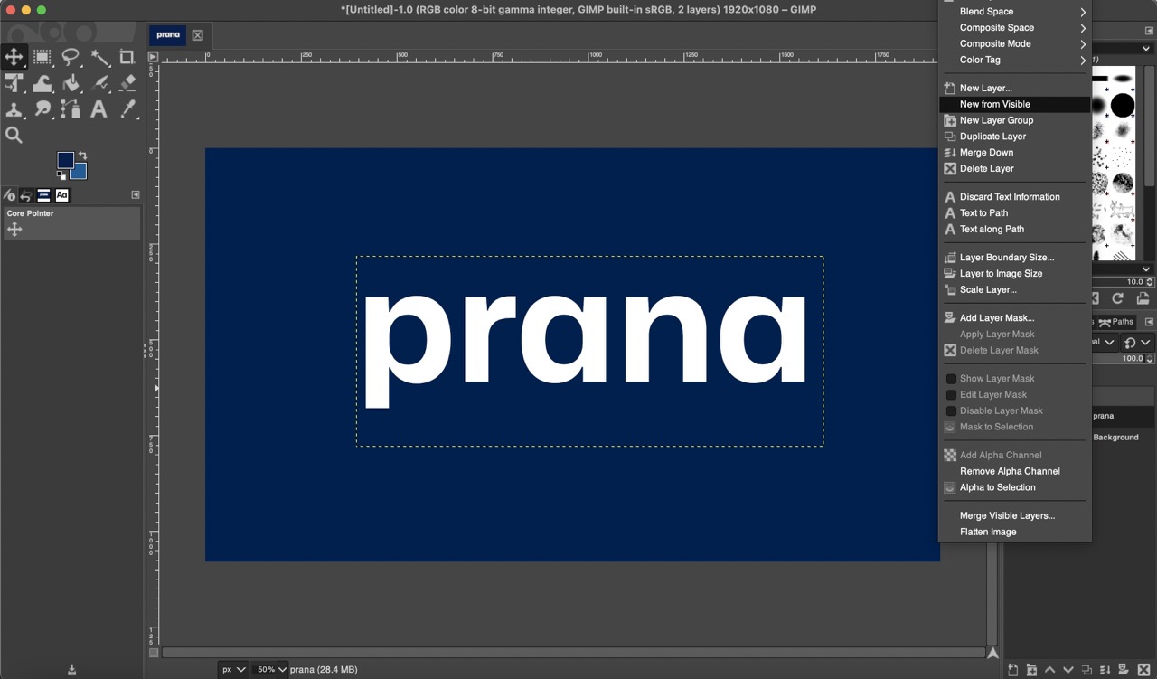
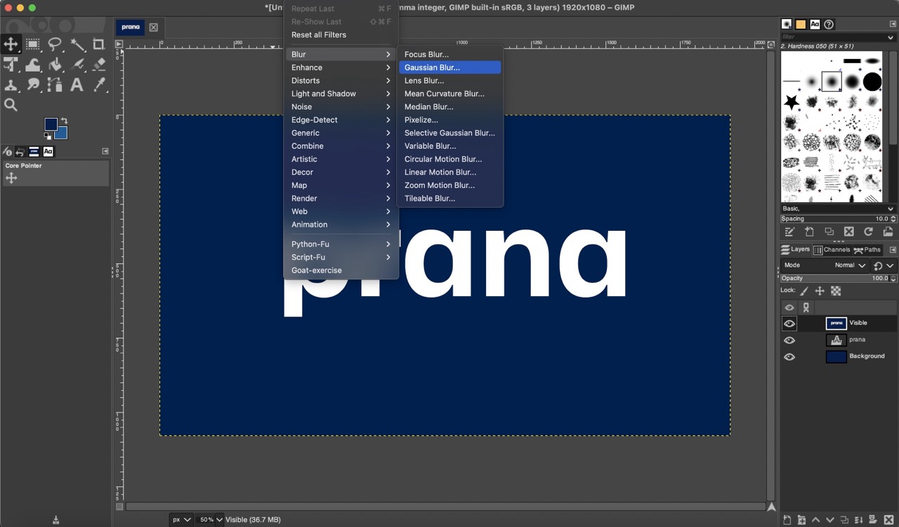
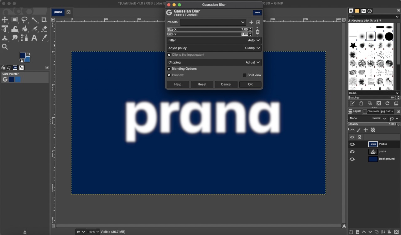
I then clicked on the text layer and selected "New from Visible" to create a new layer from the visible elements. Using this new layer, I applied a blur effect by going to "Filters," then "Blur," and selecting "Gaussian Blur," setting the size to 7.
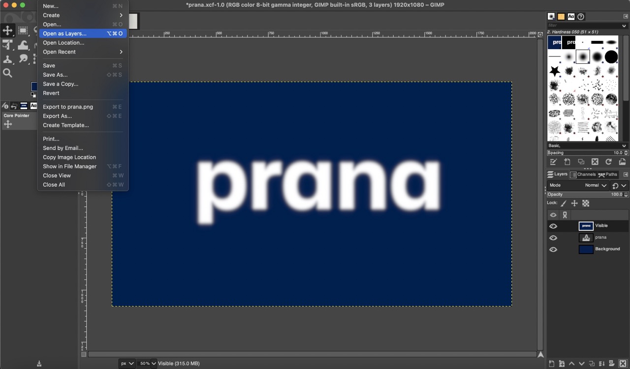
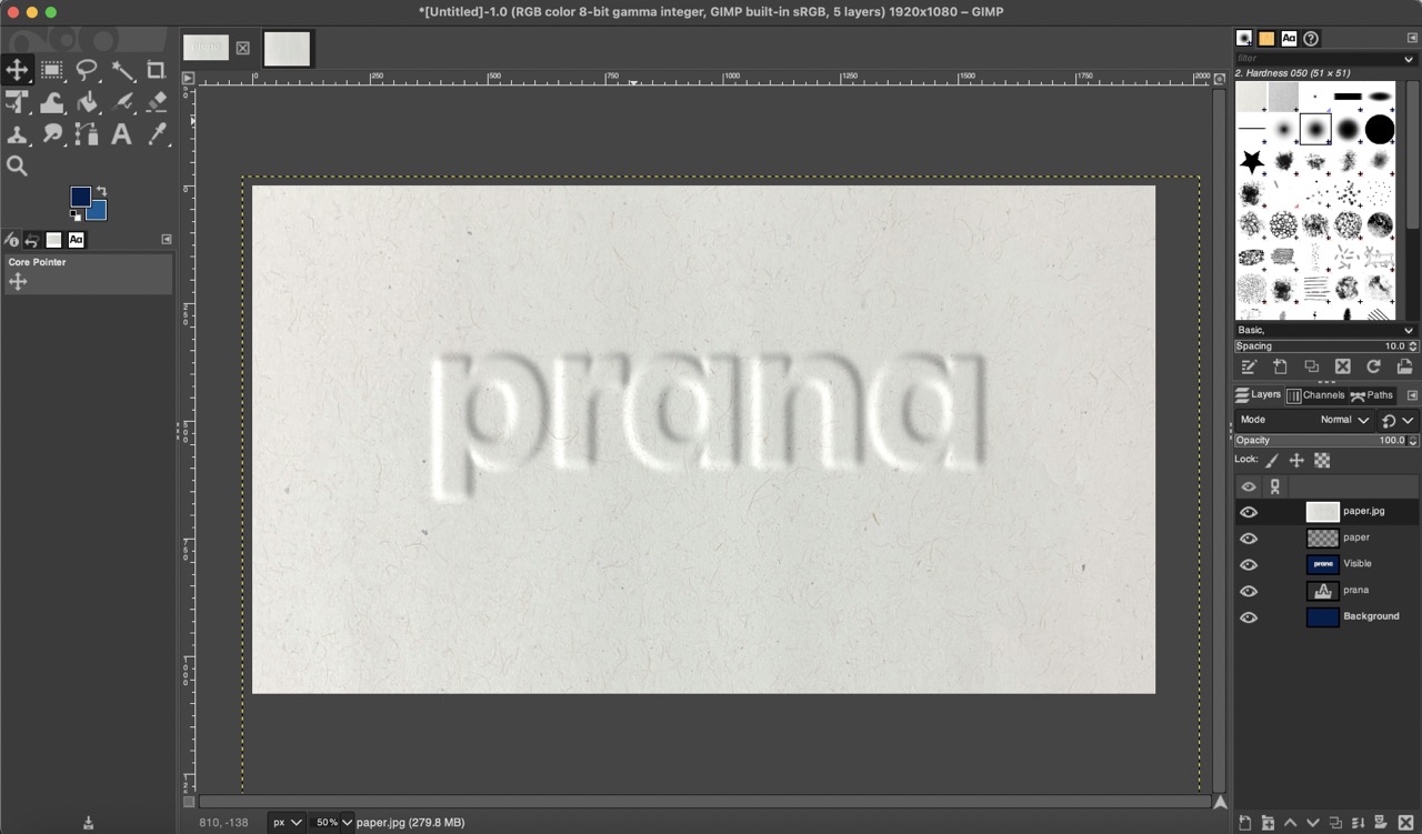
I opened a paper image by selecting "Open as Layers" and scaled it using the "Unified Transform Tool."

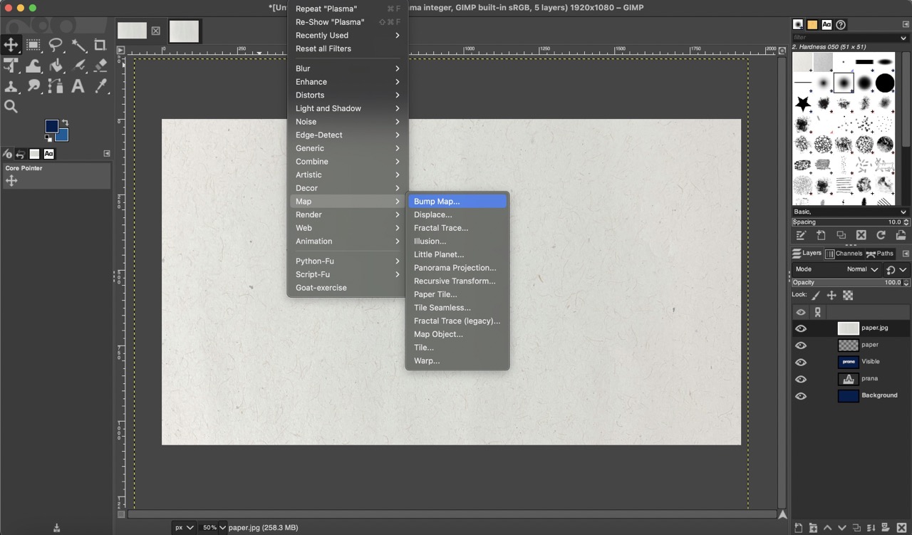
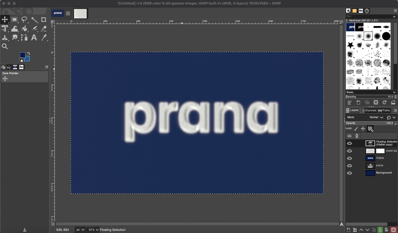
To create a textured effect on the text, I went to "Filters," "Map," and "Bump Map," then selected the visible layer to apply the bumped texture.
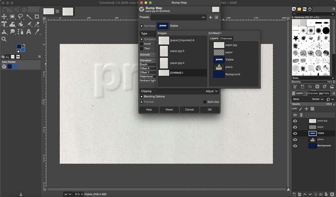
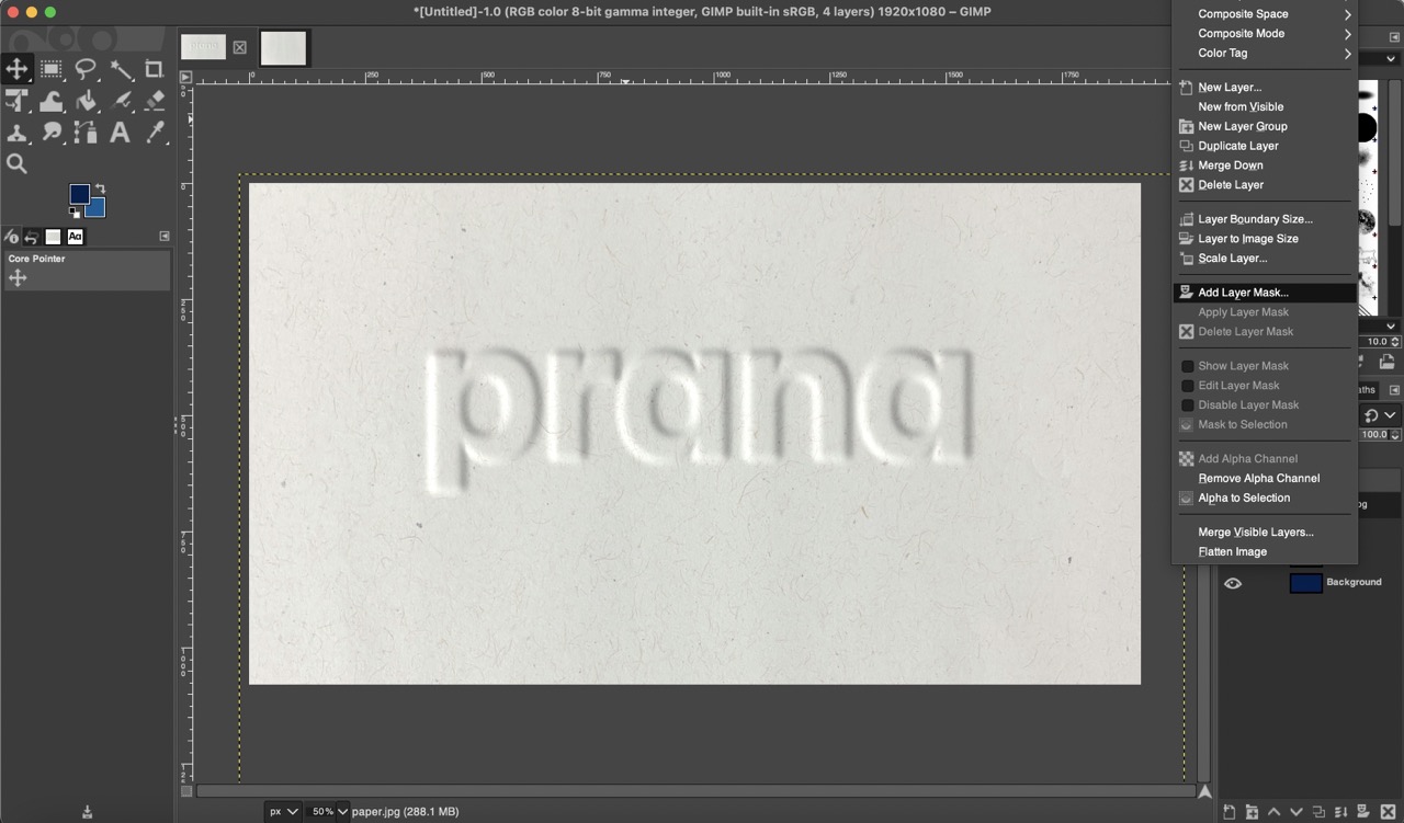
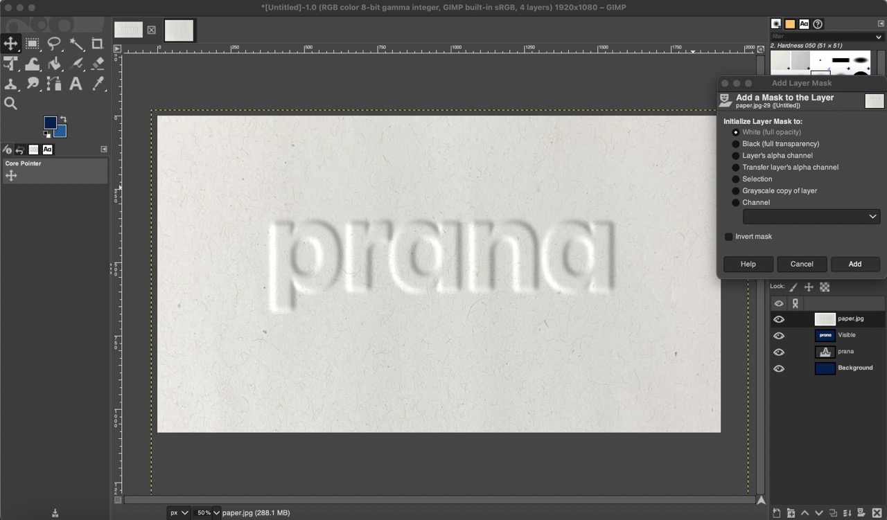
Finally, I attempted to place this texture on a blue background by adding a layer mask with "White (Full Opacity)."
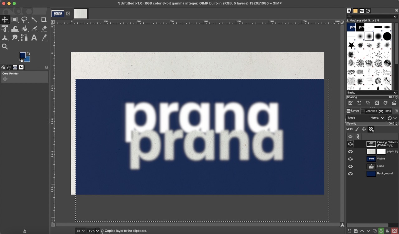
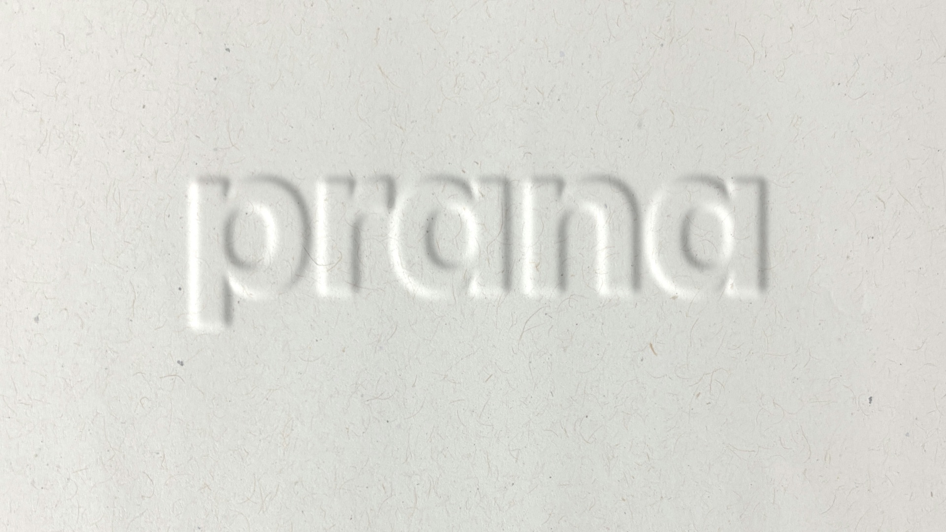
However, I wasn't satisfied with the final result on the blue background. I did like the textured text effect on the paper. It looked elegant and could be suitable for packaging design and brand identity.
3D model - fusion 360
As I'm new to modeling with Fusion 360, I decided to watch a couple of Youtube tutorials to understand the basics of this software. Once I familiarized myself with the location of each tool and the basic modeling structure, the process became quite straightforward. My background in various programs like Rhino, Inventor, AutoCAD, and SolidWorks helped me quickly adapt to Fusion 360.
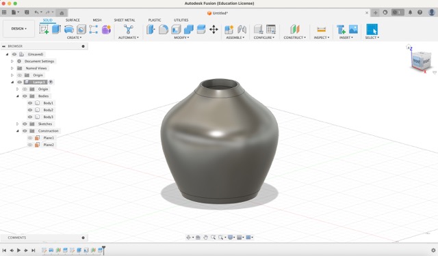
I followed an example video to create the following lamp.
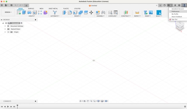
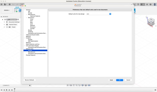
- To start, click on your profile icon on the top right corner and select “Preferences”. Then, under “Default Units” navigate to 'Design' and make sure the units are set to millimeters (mm). Millimeters are recommended for design work due to their precision.
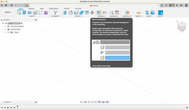
- Next click on “New Component”, organizing your work into components helps keep everything structured. It will ask you to name the component.
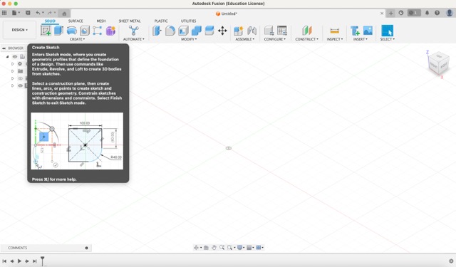
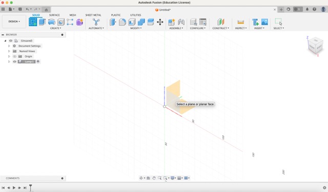
- To start creating your model, click on “Create Sketch”. You will always be asked to choose a plane for the sketch, in this case, select the front plane.
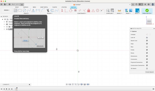
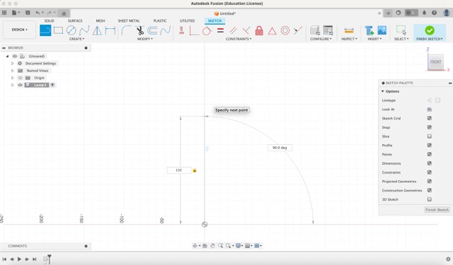
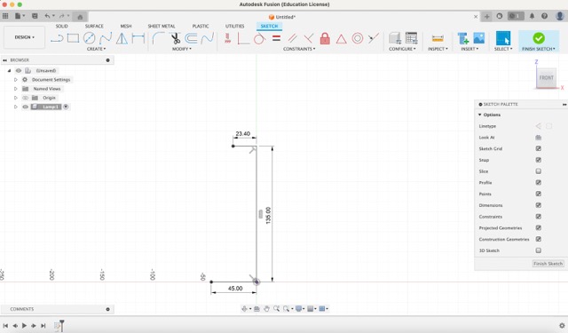
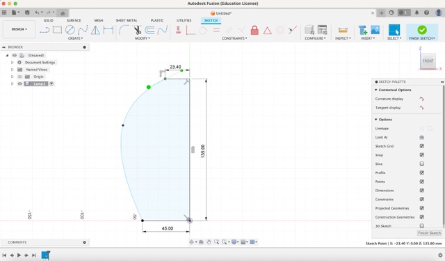
- Use the line tool to create a vertical line of 135 mm and two horizontal lines measuring 23.40 mm and 45 mm, as shown in the following images.
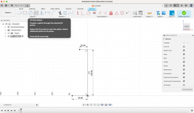
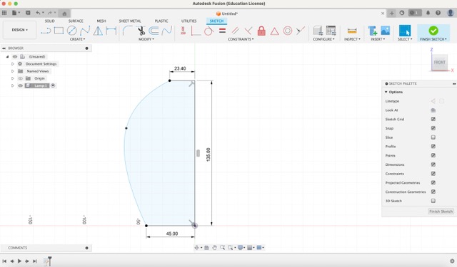
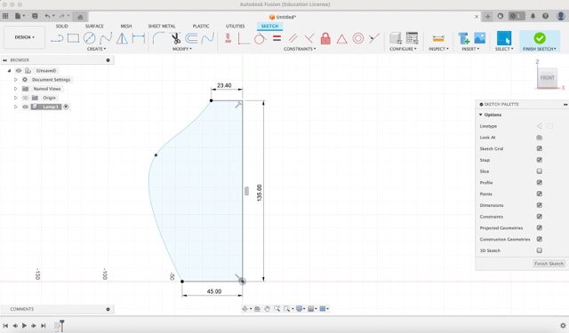
- Next, select the fit point spline tool and create a curve similar to the one shown below. You can modify this curve by clicking on the top point and adjusting the handles.
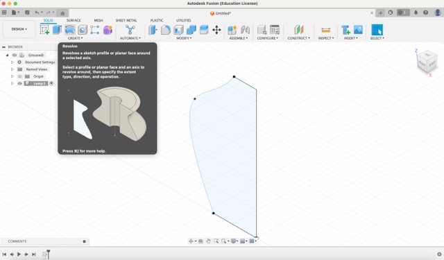
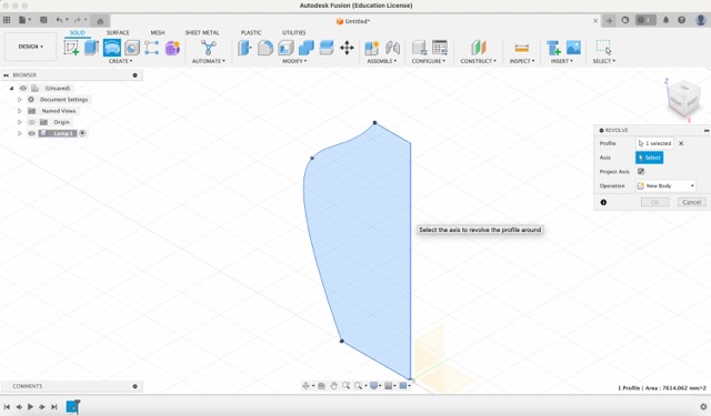
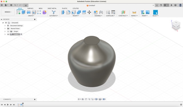
- Finish the sketch, and click on the revolve tool. It will ask you for the profile (the closed curve created earlier) and the axis (the vertical line).
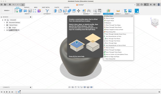
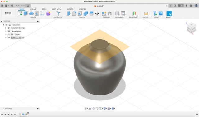
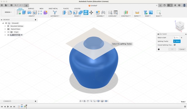
- From here, we want to split the body, to do this, open the construct menu and click on 'Offset Plane'. Select the top circular face and enter a - 8 offset.
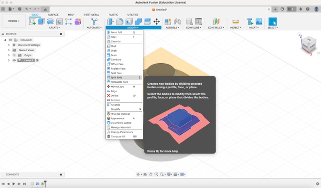
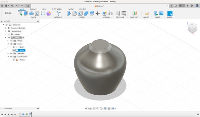
- Then, under the modify menu, select 'Split Body'. First, select the body to split, then the splitting tool (the plane created earlier).
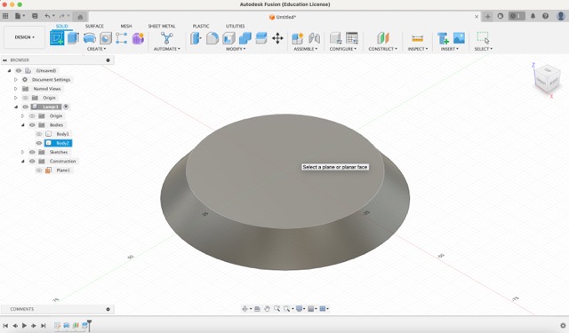
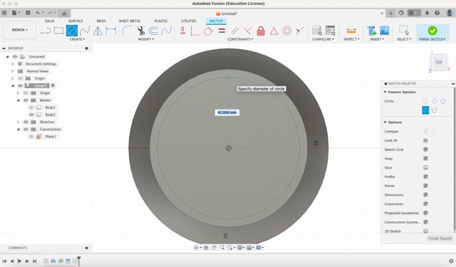
- Now hide the body and let's focus on the top part first. Create a new sketch and choose the top circle as the plane. Use the ‘Center Diameter Circle’ tool to create a circle measuring 42 mm.
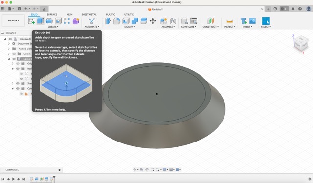
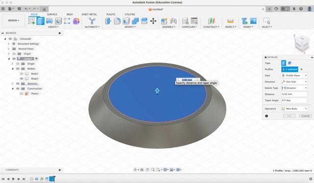
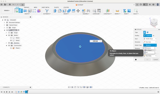
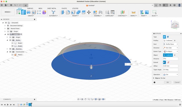
- To create a hole, use the extrude tool. Select the top circle, change the extent type to 'To Object', and select the bottom circle while pressing the command key.
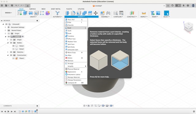
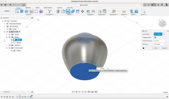
- Hide this element and show the hidden body. Under the modify menu, select the shell tool. Click on the top and bottom circle and enter 1.6 mm.
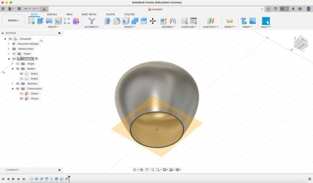
- Repeat the steps to split the body. Open the construct menu, click on 'Offset Plane', select the bottom circular face, and enter a -8 mm offset. Then, under the modify menu, select 'Split Body'.
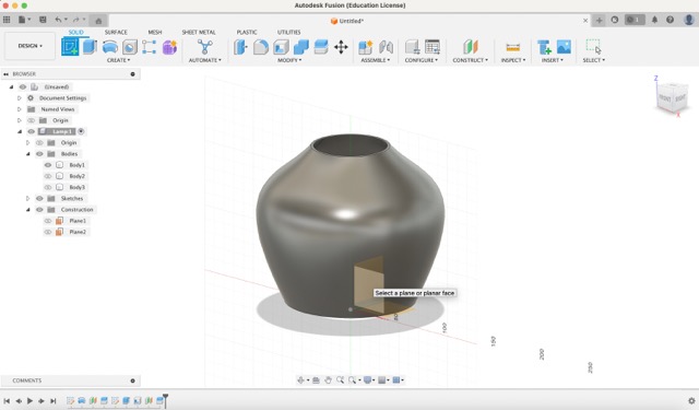
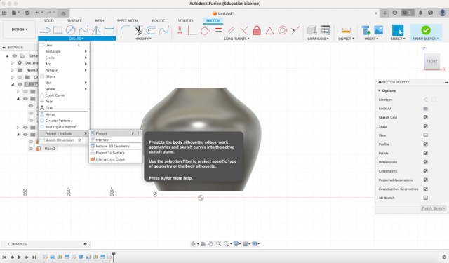
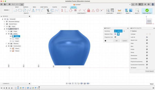
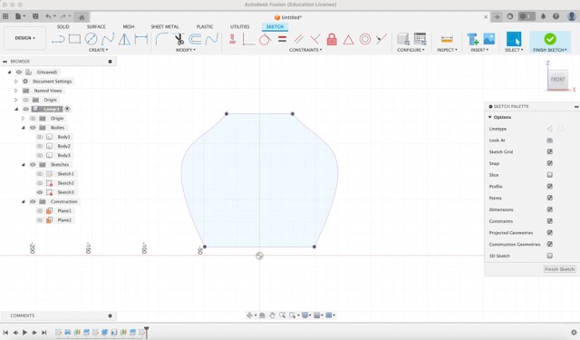
- Now, hide both trimmed bodies and start a new sketch on the front plane. Under the create menu, select 'Project' and choose the body.
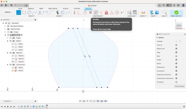
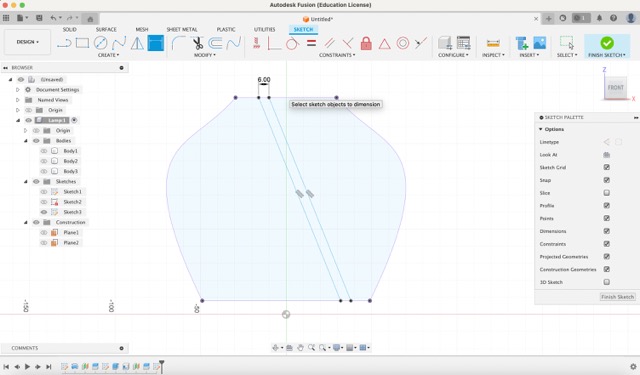
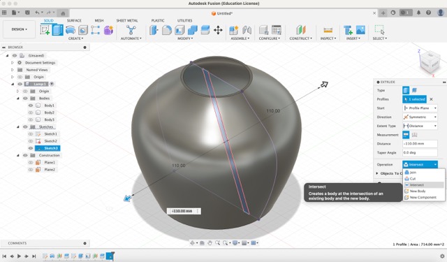
- Hide this body and let's create geometries that will be projected on the surface of the body. With the line tool, create two parallel lines, if the constraint is not done automatically, you can select this option inside the constraints menu. With the dimension tool, create a dimension that constrains the separation between the two lines to 6 mm.
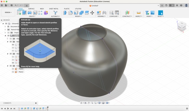
- Turn on the body and use the extrude tool to select the traced rectangle. Change the direction to ‘Symmetric’ and the operation to ‘Intersect’.
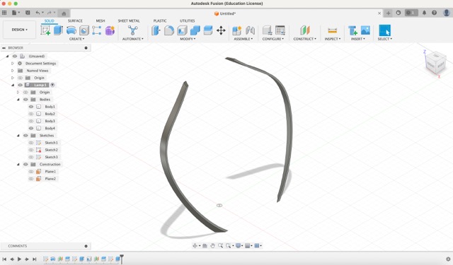
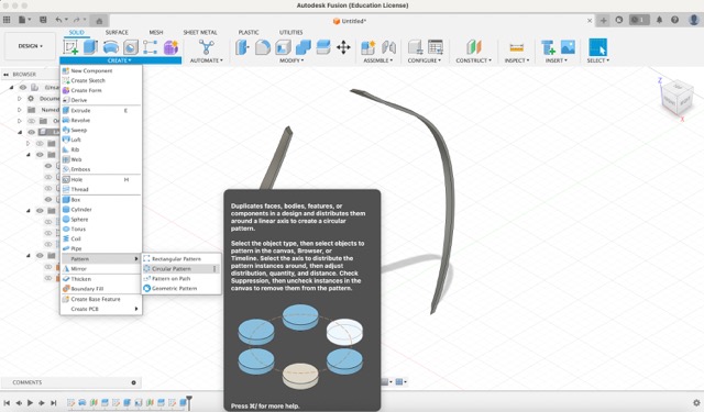
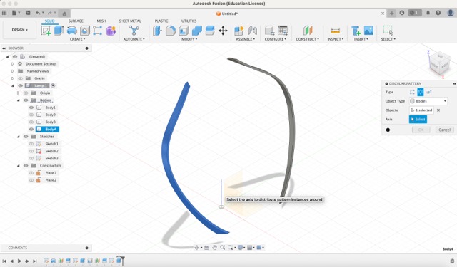
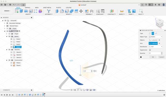
- Under the ‘Create’ menu, select 'Pattern' and then 'Circular Pattern'. Select the first body, as shown in the images below, then choose the vertical axis, and enter 22 for the quantity.
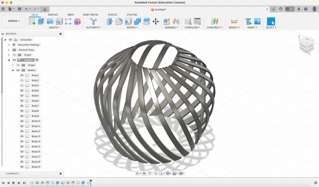
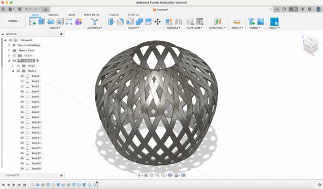
- Repeat this step for the other body.
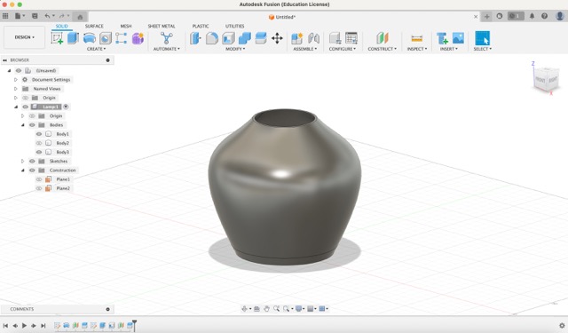
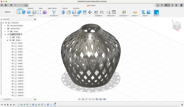
- Turn on the base and top body to view your final geometry. It's important to note that any actions (sketches, extrusions, etc.) can be modified without breaking the object's history. Modifying any of these actions will automatically update subsequent actions.
3D model - rhino
Origami simulator
To model my final project, I decided to use Rhino, as I am familiar with the interface and can quickly explore various design possibilities. Since my project is an origami lamp, I used an origami simulator to aid in the modelling process.
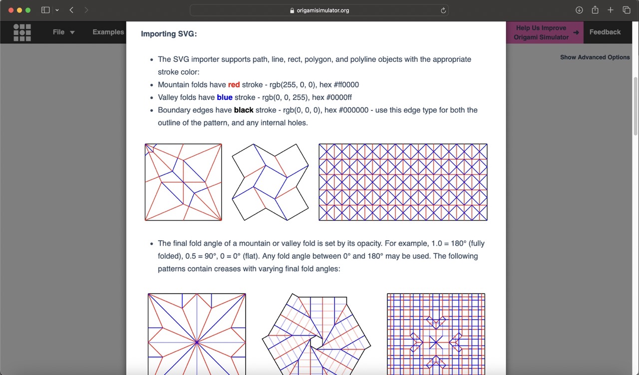
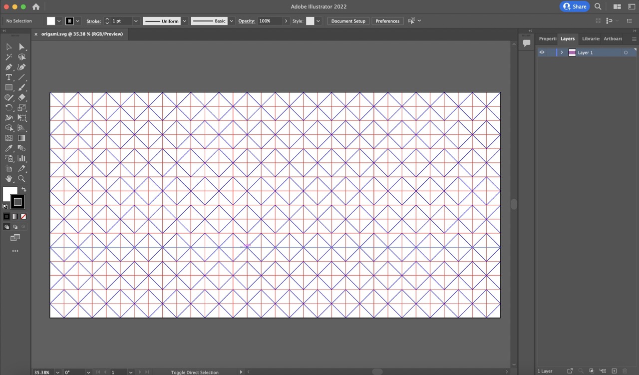
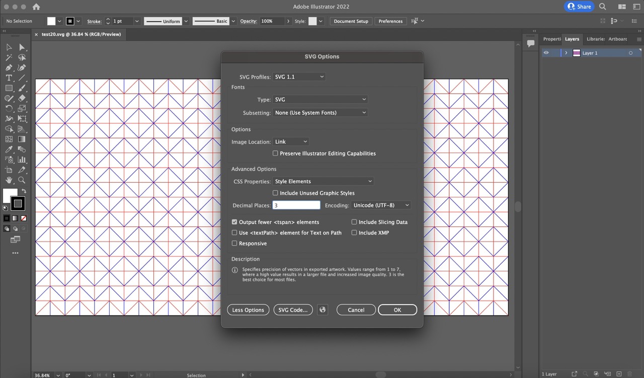
On the main page of the origami simulator, under the 'file' section, there is a 'design tips' section that explains how to import the SVG file of your origami design. Following these tips, I began creating the pattern for the origami structure in Illustrator, considering both the mountain and valley folds.
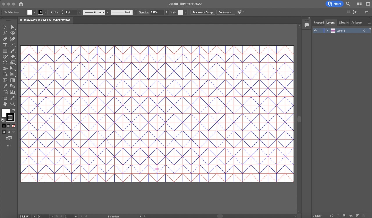
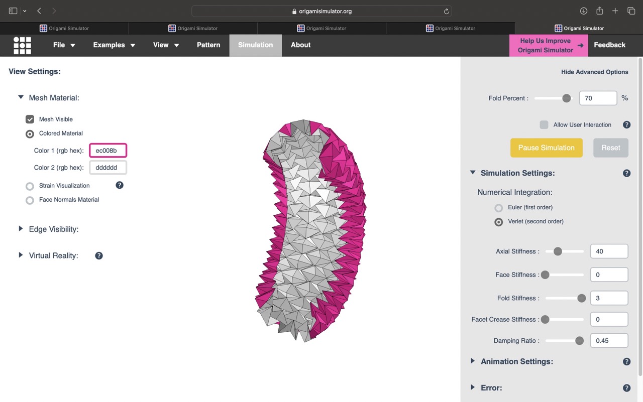
After finalizing the pattern, I imported the SVG file into the origami simulator and tested different fold percentages. I achieved a result that was close to what I wanted but realized that the last fold was not correct. I returned to Illustrator to adjust the pattern, conducting several tests to determine the correct design.
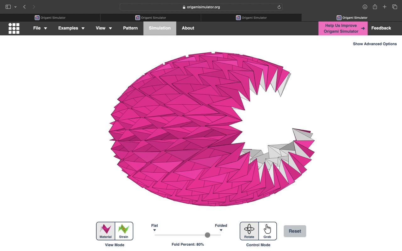
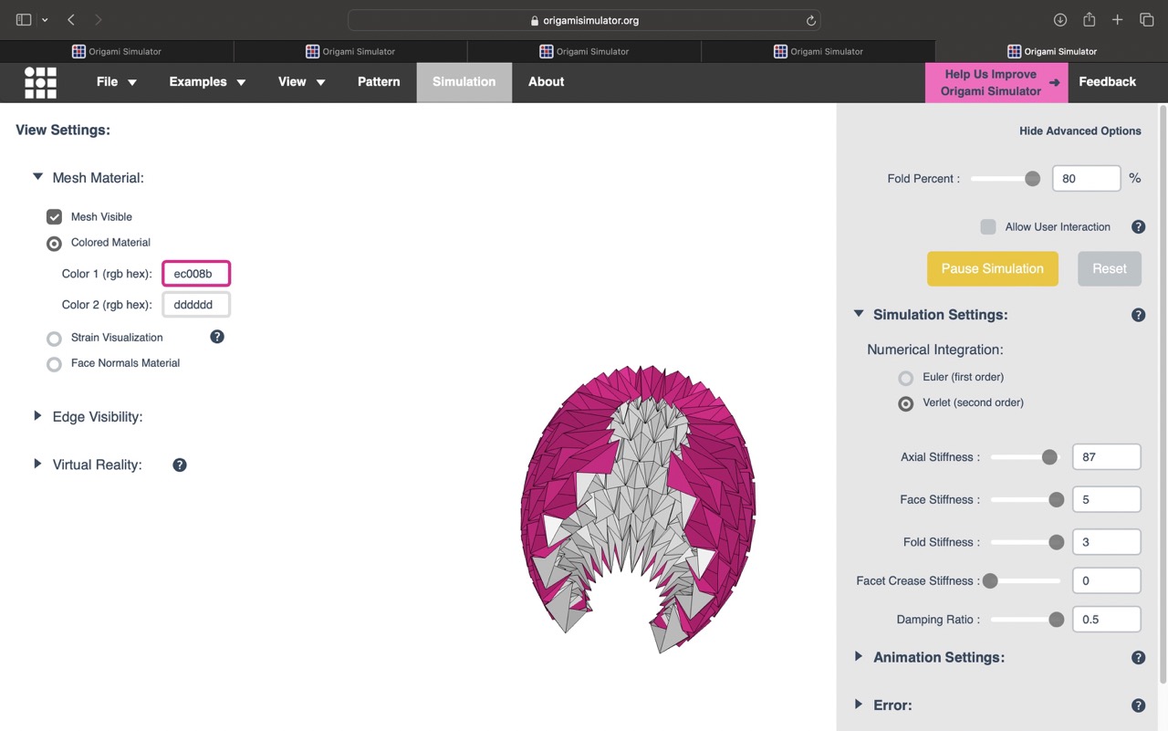
I returned to Illustrator to adjust the pattern, conducting several tests to determine the correct design. Once I had the right pattern, I ensured the files were saved according to the specifications listed in the 'design tips'. I imported the SVG file into the simulator again and experimented with fold percentages and other parameters to model the desired structure. The software does not allow for 'pasting' some of the folds before starting the animation, so it was challenging to find the right parameters that closely matched my vision.
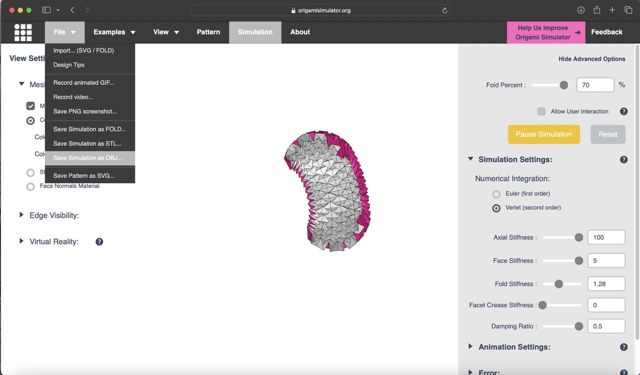
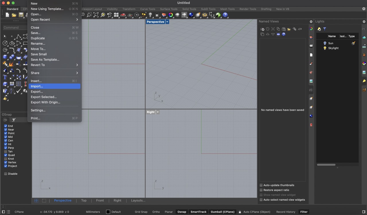
Finally, when I had the desired shape of the model I exported it as a '.obj' file from the simulator, opened Rhino, and imported the .obj model. Now, I am ready to start modeling the design.
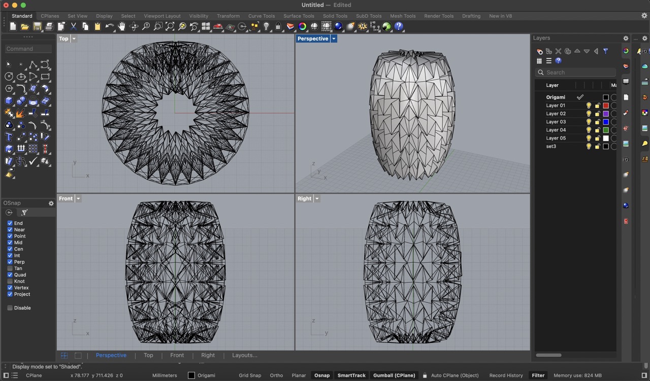
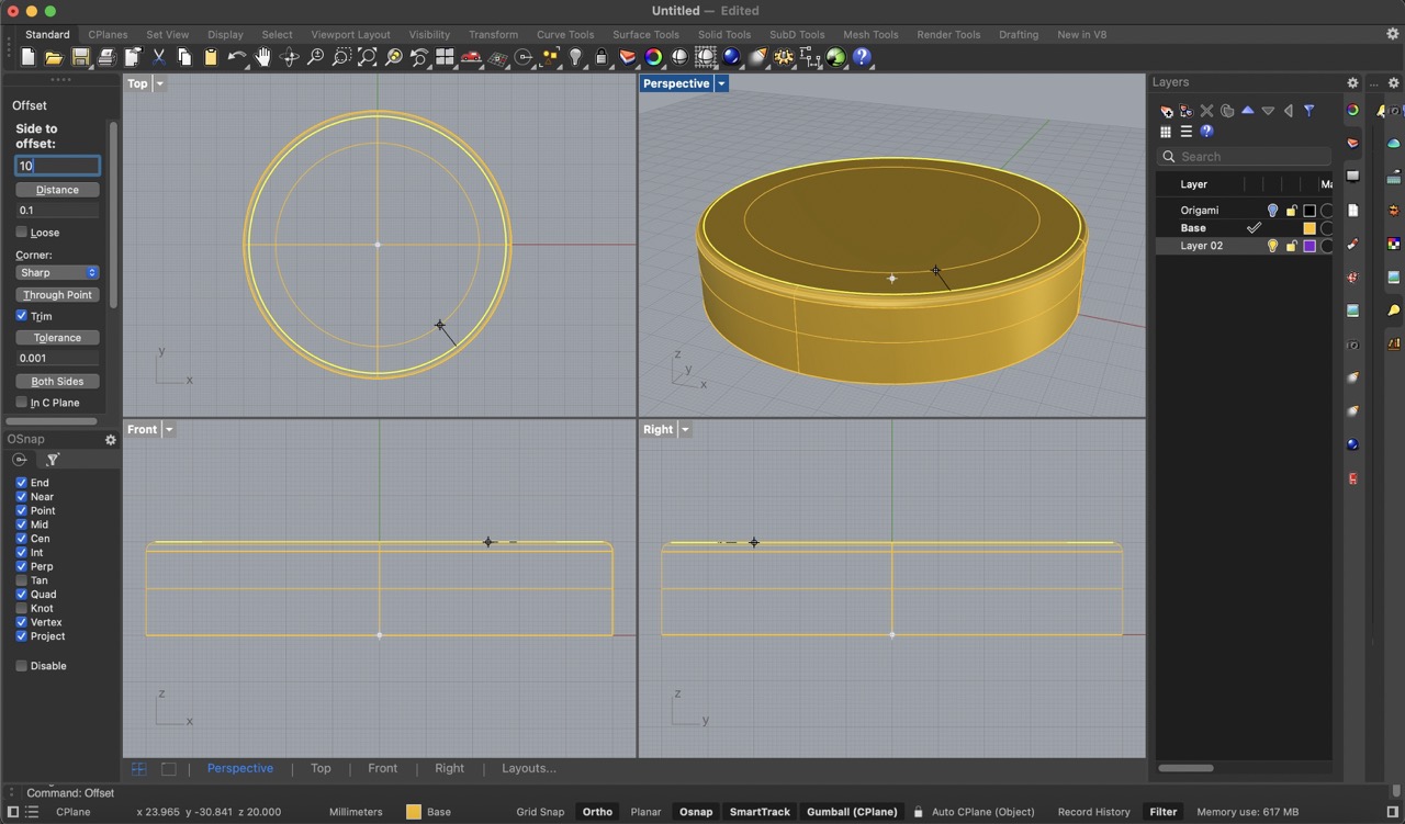
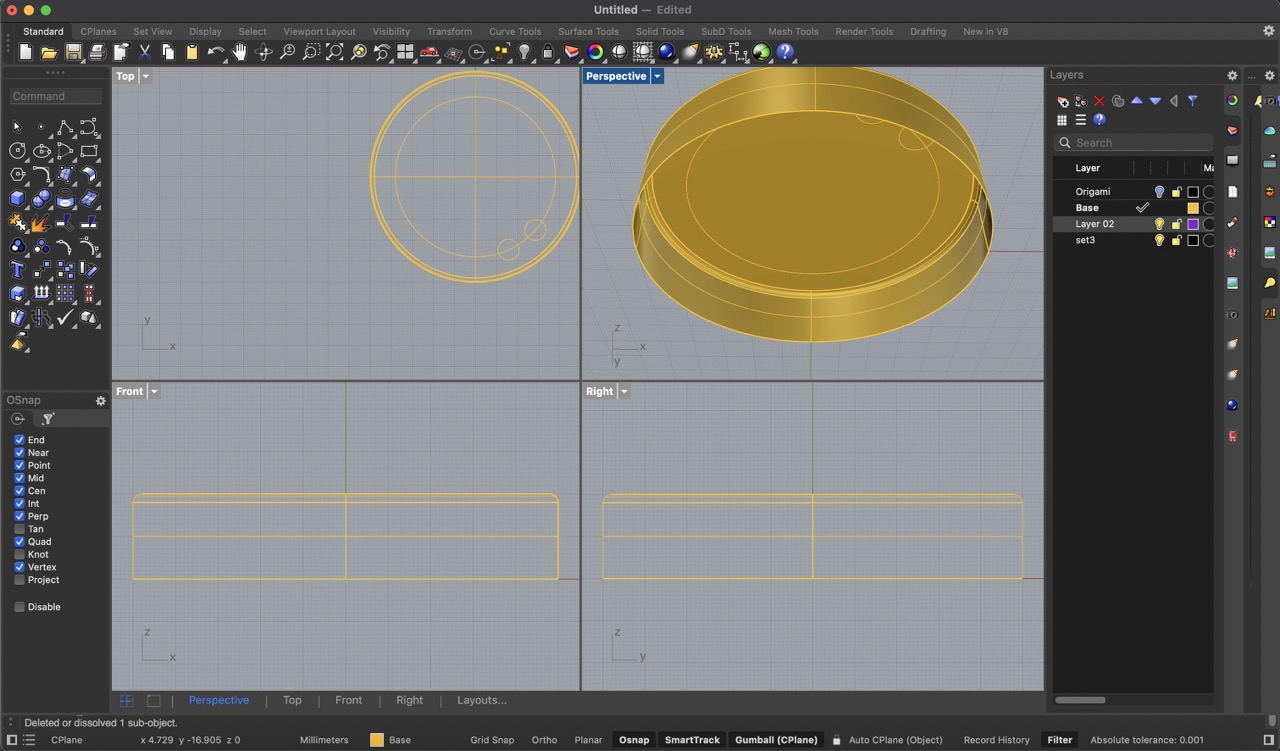
To start, I hid the origami structure and began modeling in a new layer to have a clearer view. I decided to model and design the base first. I began by creating a cylinder with a 50 mm radius and a 20 mm height, I also applied a 2mm edge fillet.


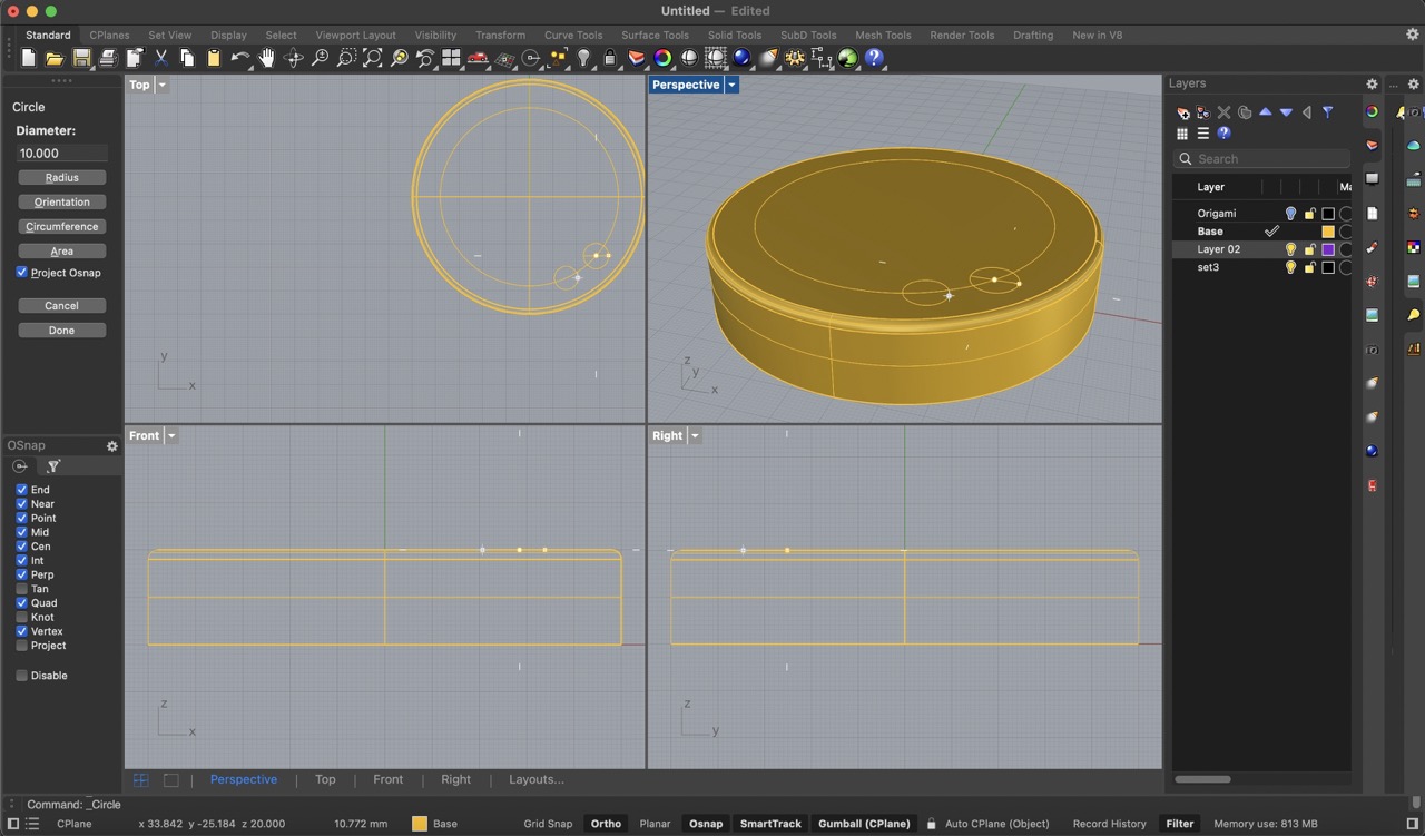
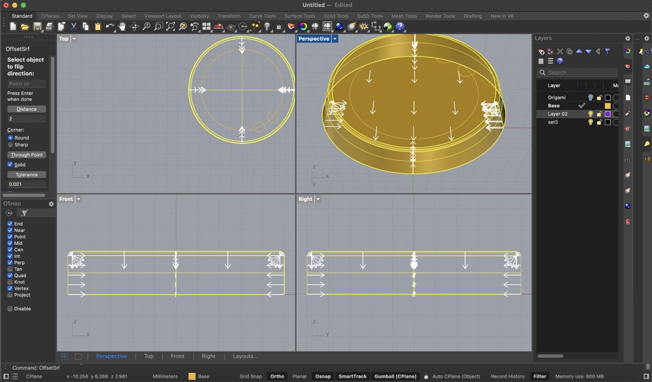
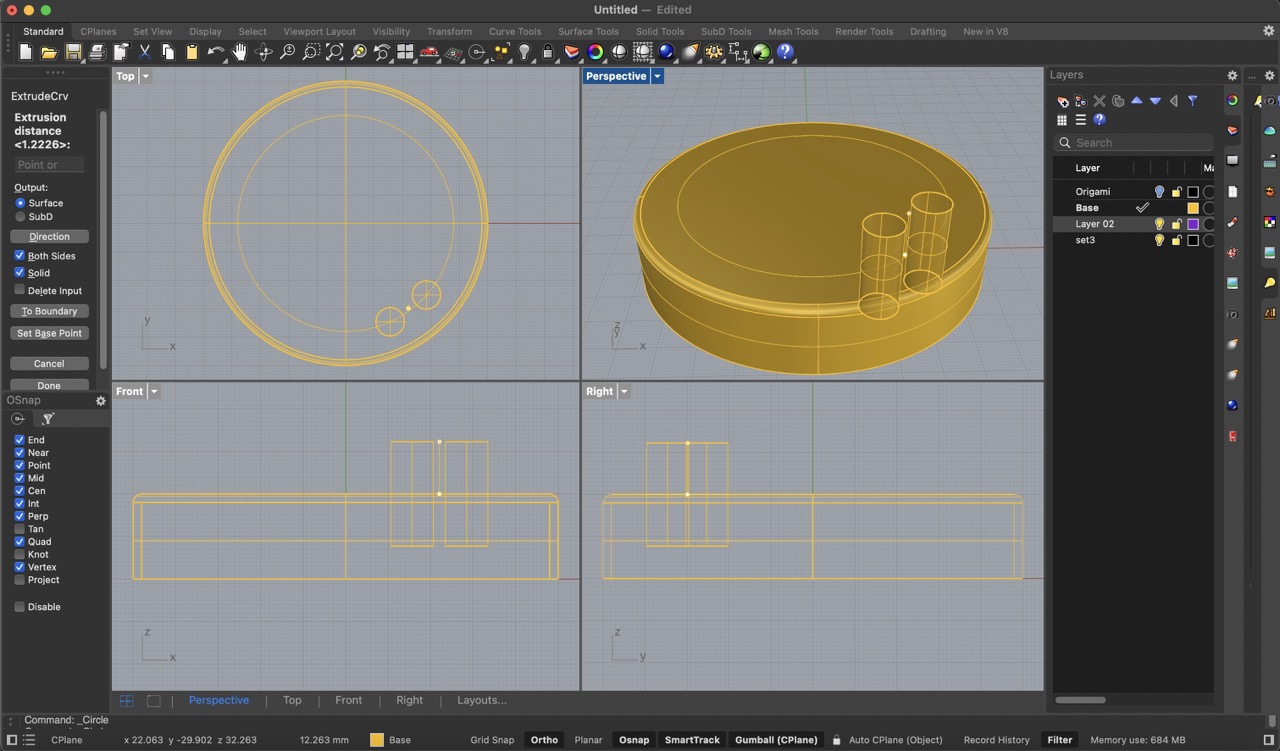
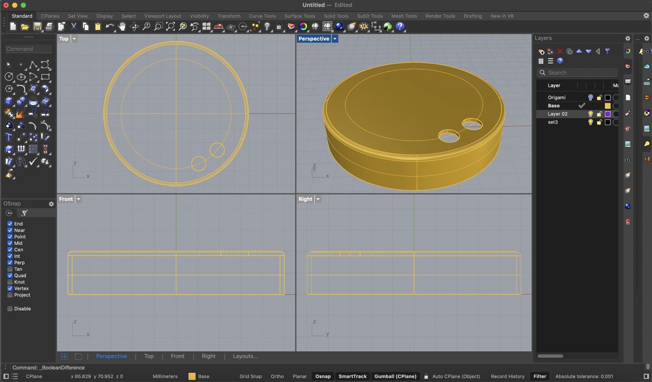
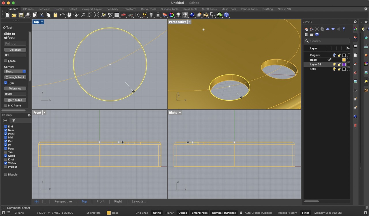
Next, I offset the top diameter by 10 mm inwards. Using this curve, I traced two circles with a 10 mm diameter each. Before extruding these circles and performing a boolean difference, I needed to remove the bottom face. I did this by using 'command + shift' to select and delete that face. Then, using 'offset surface', I gave the geometry a 2 mm thickness. After that, I extruded the cylinders and used a boolean difference to create the holes for the buttons on the body of the base.
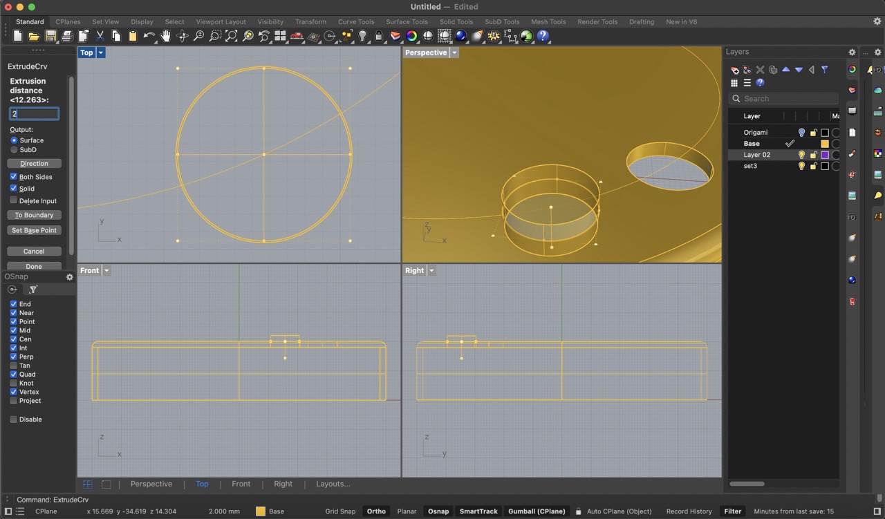
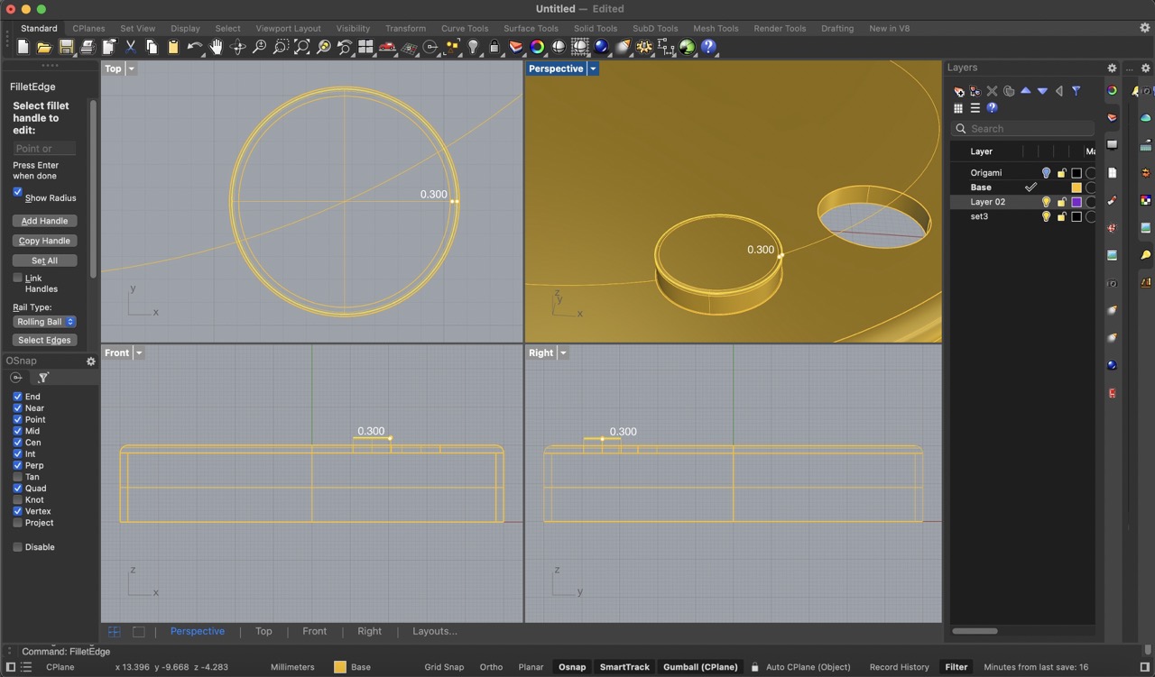
I then offset the edge of the body hole by 0.1 mm to create the buttons. I extruded this curve by 2 mm, filleted the edge by 0.3 mm, and finally moved it down by 1.9 mm so that only 0.1 mm sticks out.

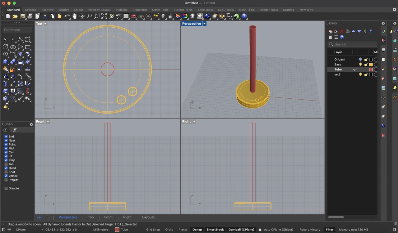
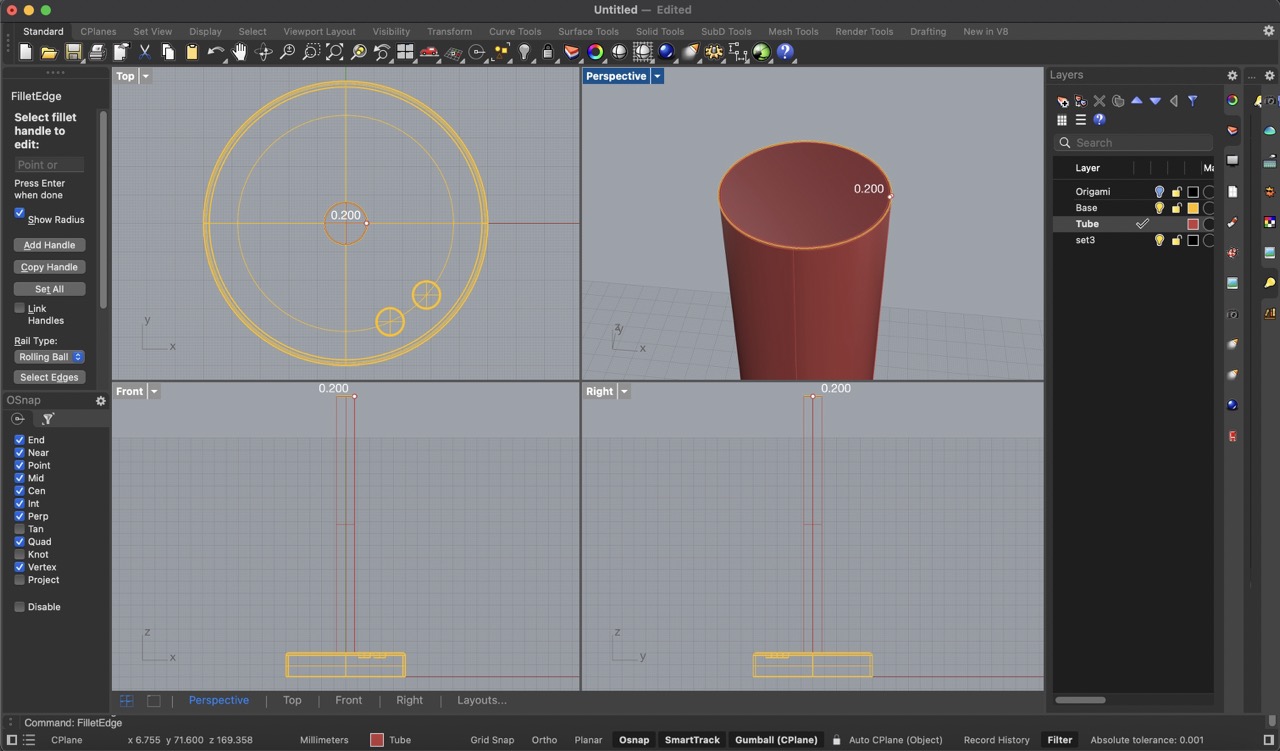
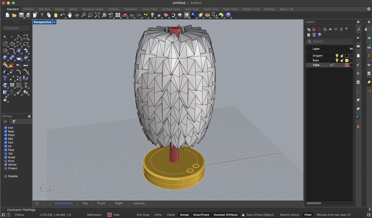
Finally, I created a cylinder with a 7.5 mm diameter and a 215 mm height. I applied a 0.2 mm fillet to the top edge. Then, I turned on the origami structure.
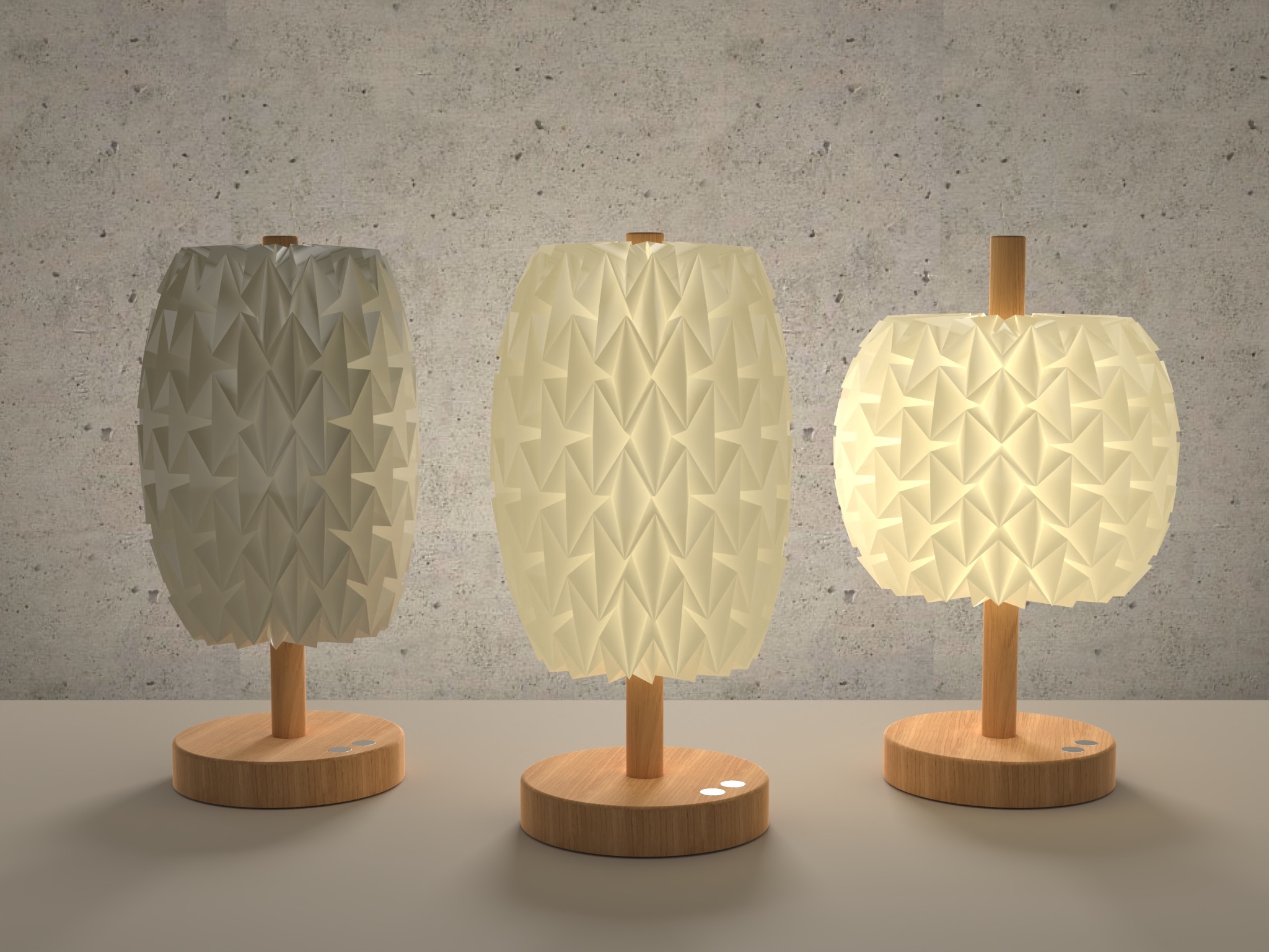
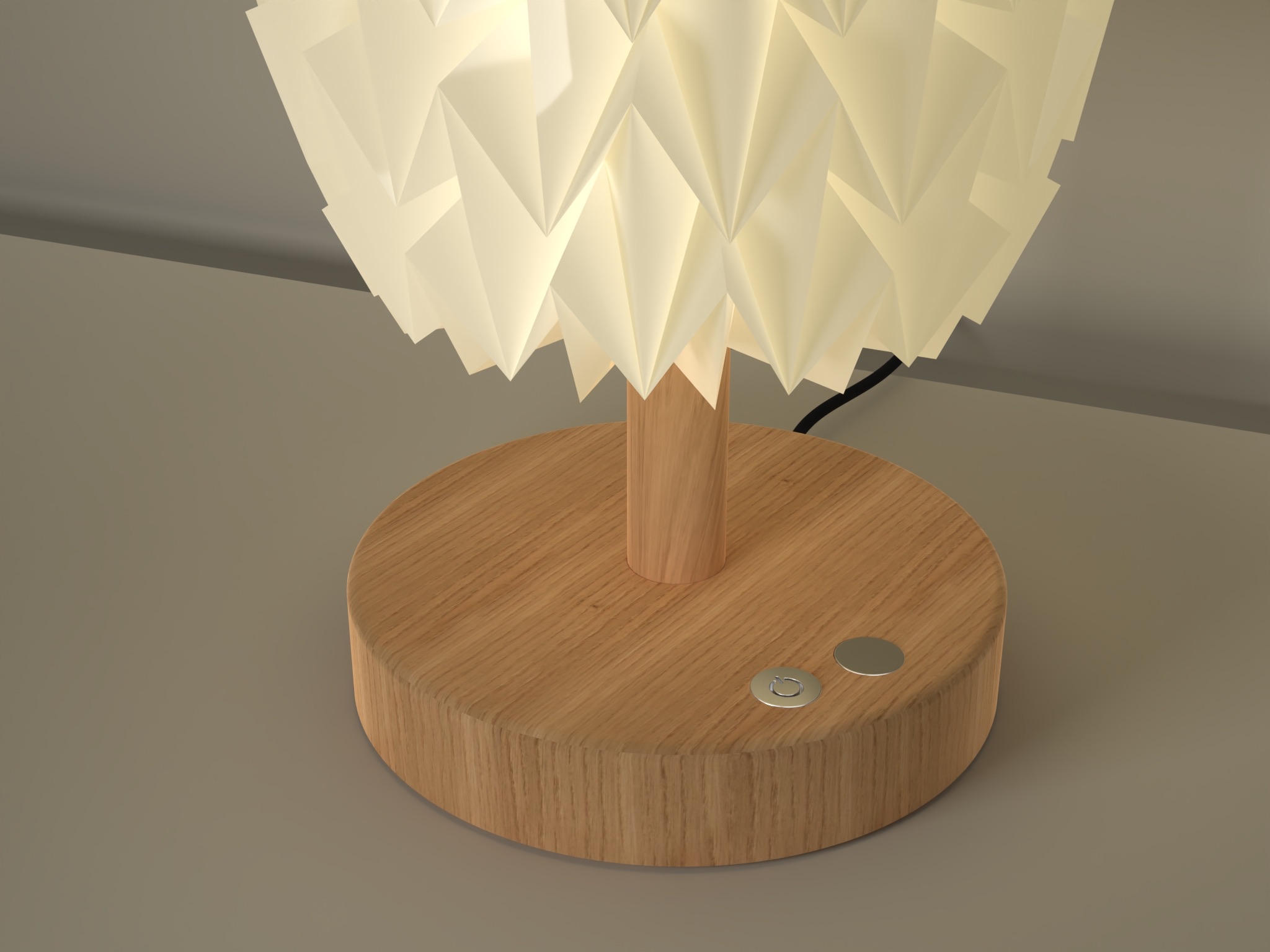
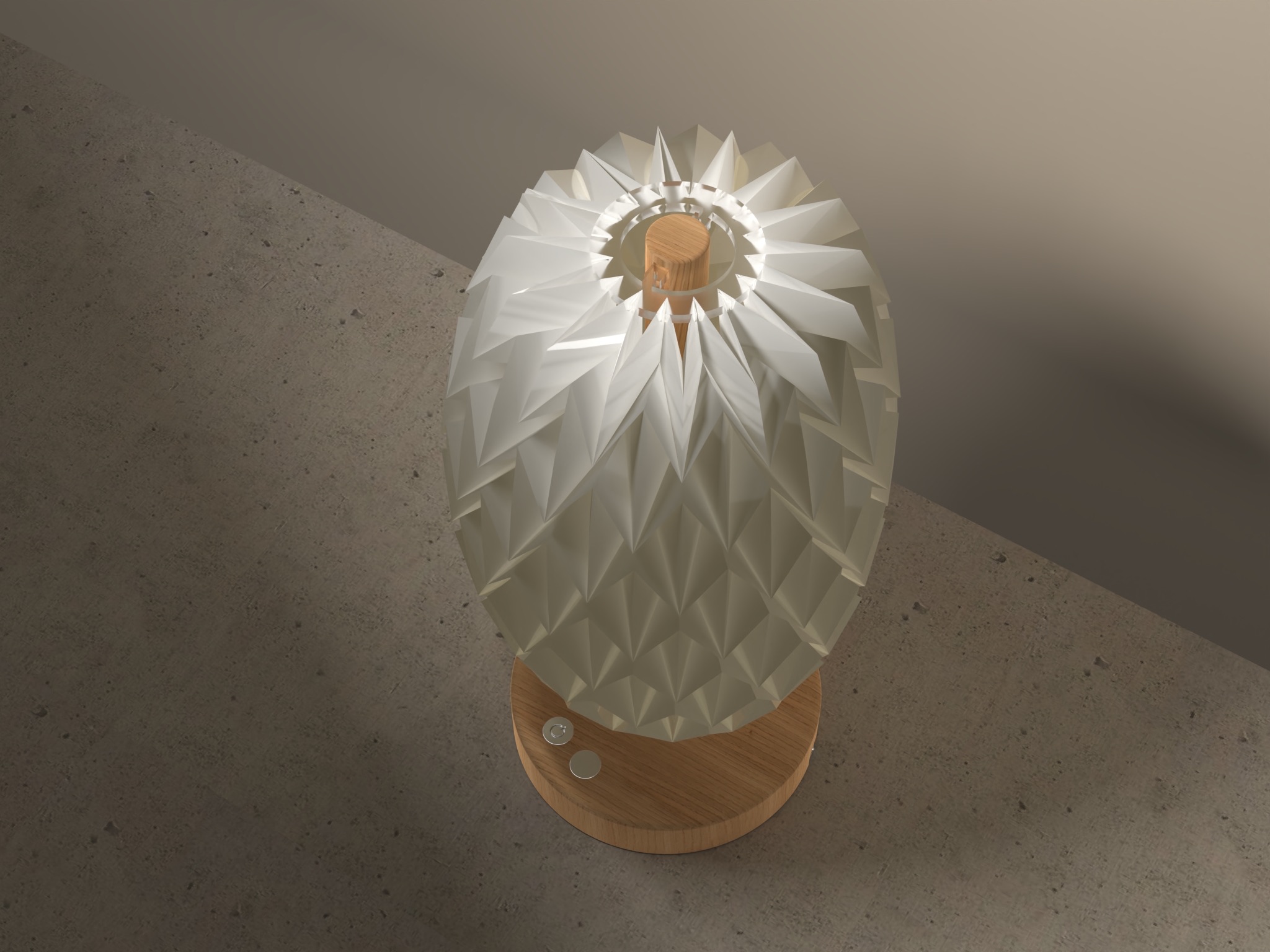
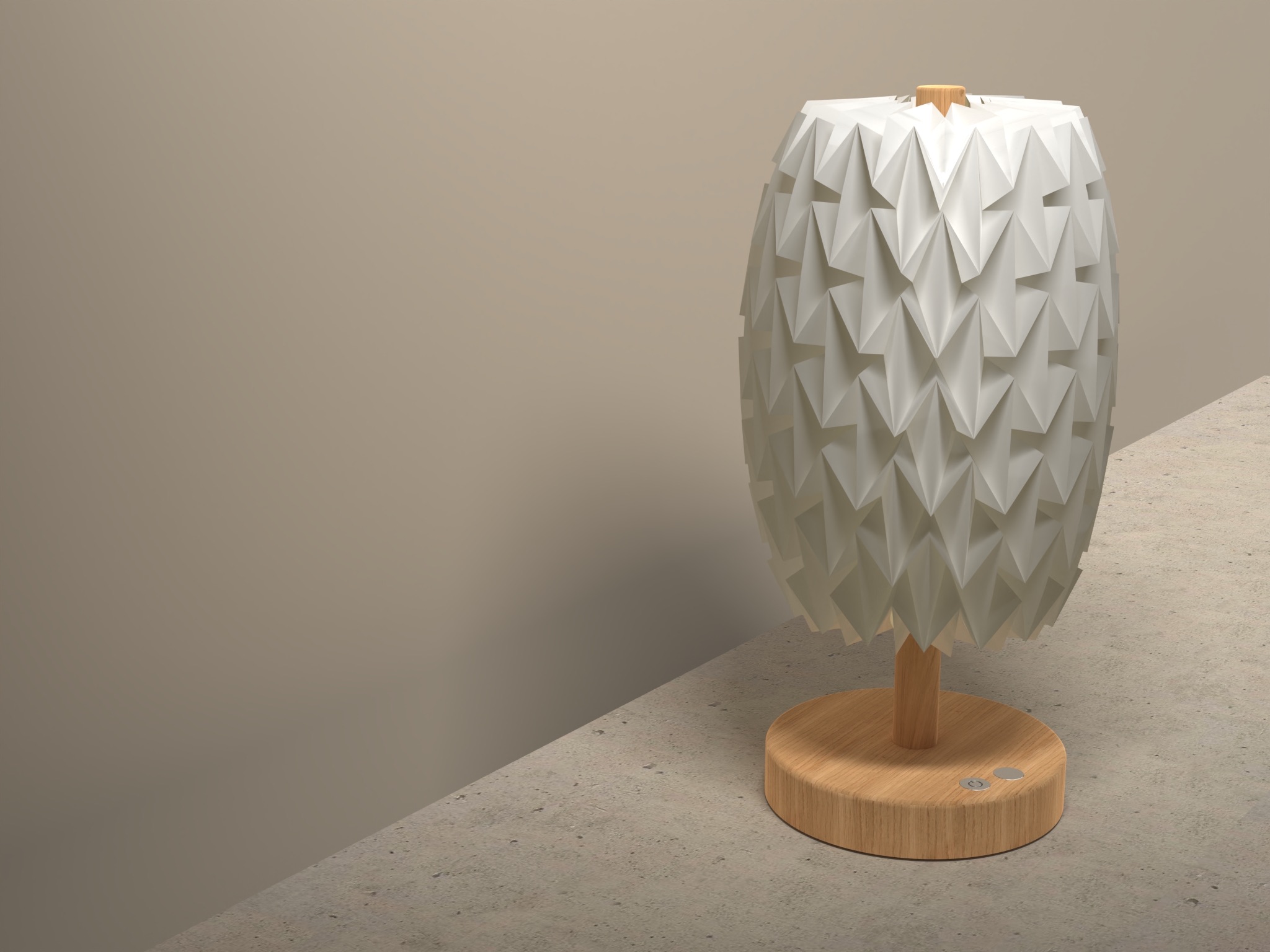
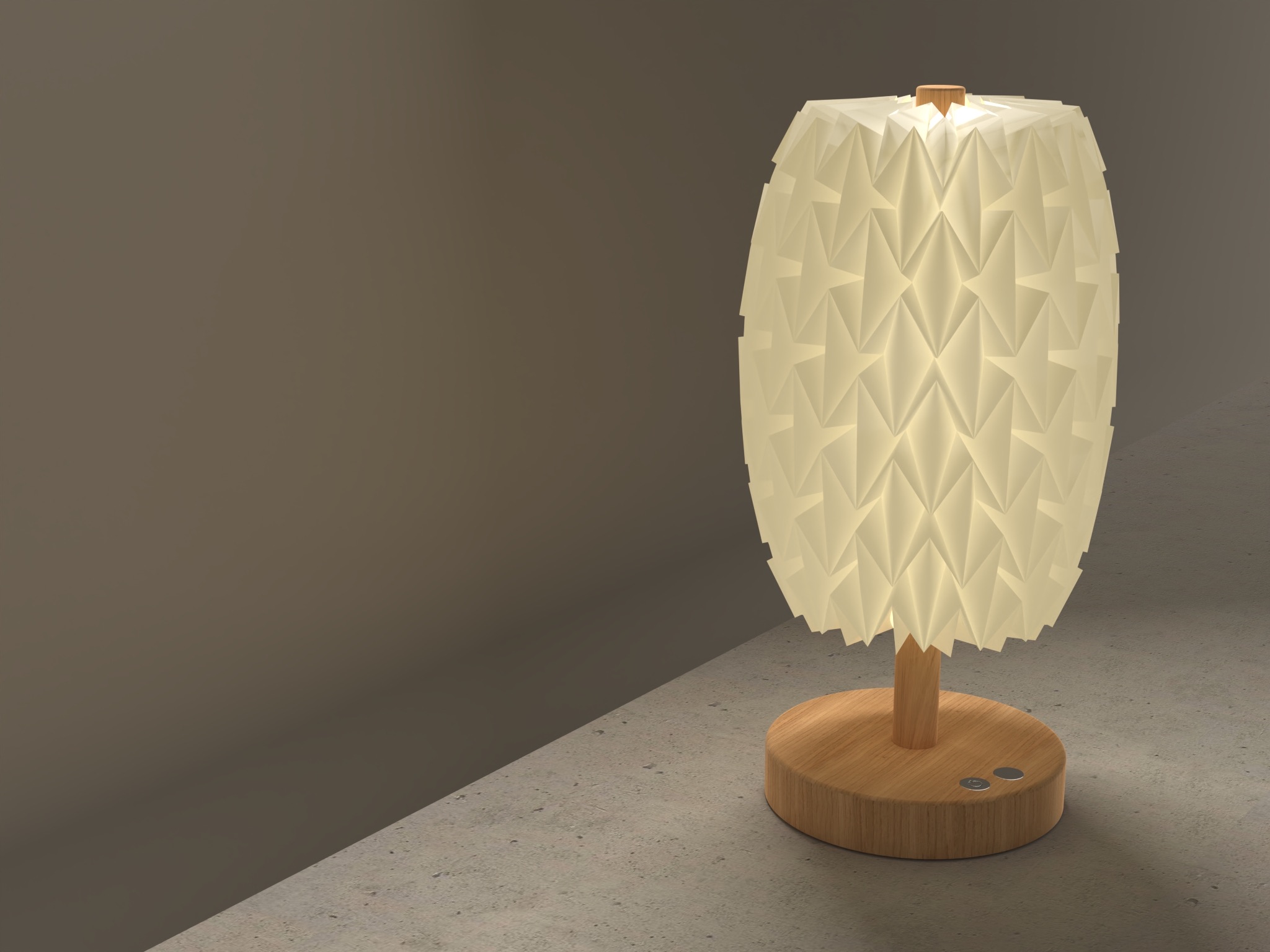
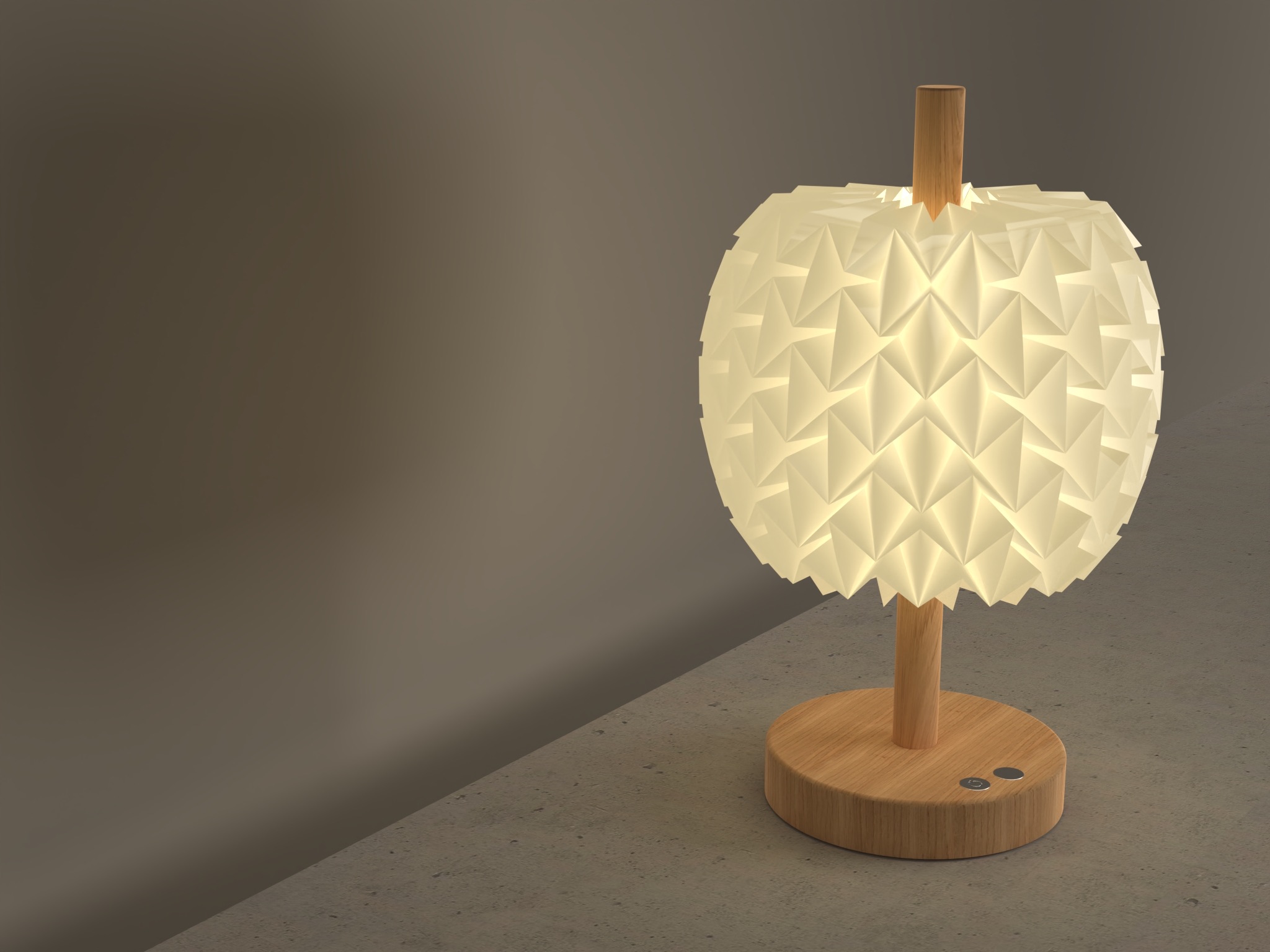
Final renders
Conclusion
I really enjoyed working with Fusion 360. The parametric design feature, which allows me to go back and adjust measurements effortlessly, is incredibly beneficial. In comparison, when working with Rhino, making changes or correcting mistakes often requires significant rework or starting from scratch. I'm eager to continue learning and mastering Fusion 360, as I believe it will greatly enhance my ability to execute my projects more efficiently.