Interface and application programming
For this week's assignment, the objective was to create an interface for interacting with either an output or an input. Our teacher, Rafa, gave us a class on how to use Qt Designer and explained the basics of programming an interface. I've included a link to the group's assignment where we compare various software options for creating interfaces.
Interface
An interface is a point of interaction between a user and a system or between different systems, enabling them to communicate and work together. In computing, it often refers to the graphical user interface (GUI) that allows users to interact with software through visual elements like buttons, menus, and icons.
Qt Designer
Qt Designer is a powerful tool for designing and building graphical user interfaces (GUIs) for applications using the Qt framework. It provides a drag-and-drop interface that allows developers to create and arrange widgets, such as buttons, text fields, and menus, without writing code.
Designing my interface
First of all, I started by creating a folder in my local documents named "Interfaz Andrea" in which I would save all my files and codes for the interface.
Then continued to download Qt design in the following link.
Once it was downloaded, I created a new file called "Interface.ui" and saved it in the previously created folder.
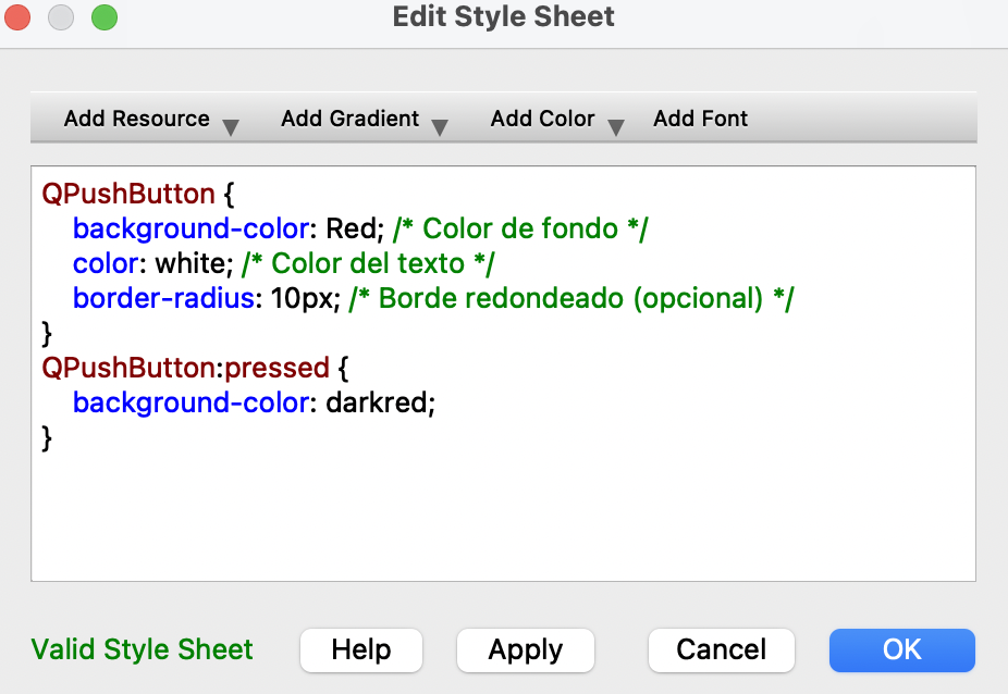
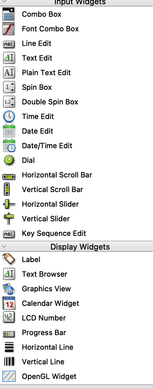
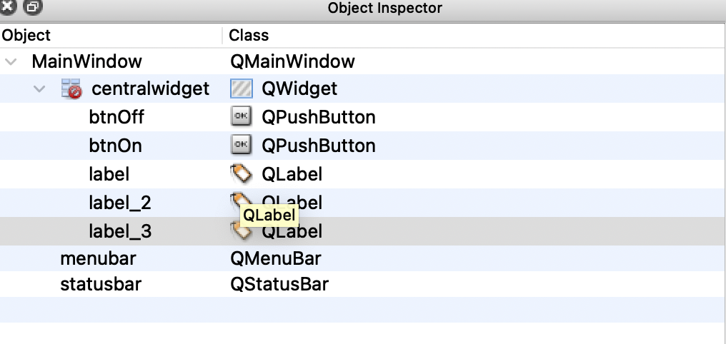
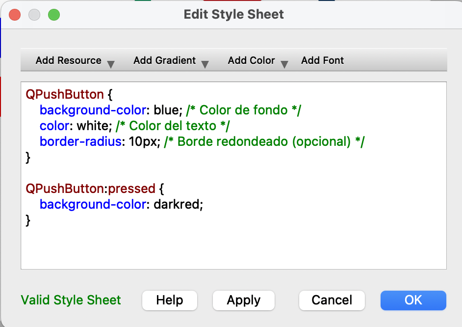
I designed the interface by dragging and dropping the elements wanted. For that I used the "label", "text" and "push button" features located on the left menu. To change their design I did a two finger click and selected "changeStylesheet" which allowed me to change the design by code.

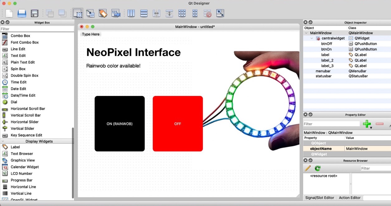
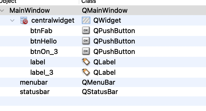
I made sure to name the elements so it would be easier to identify them while coding later on.
2
Terminal
Once I had designed my interface in Qt Designer, I saved the changes and then opened the terminal. From there, I followed the next steps.
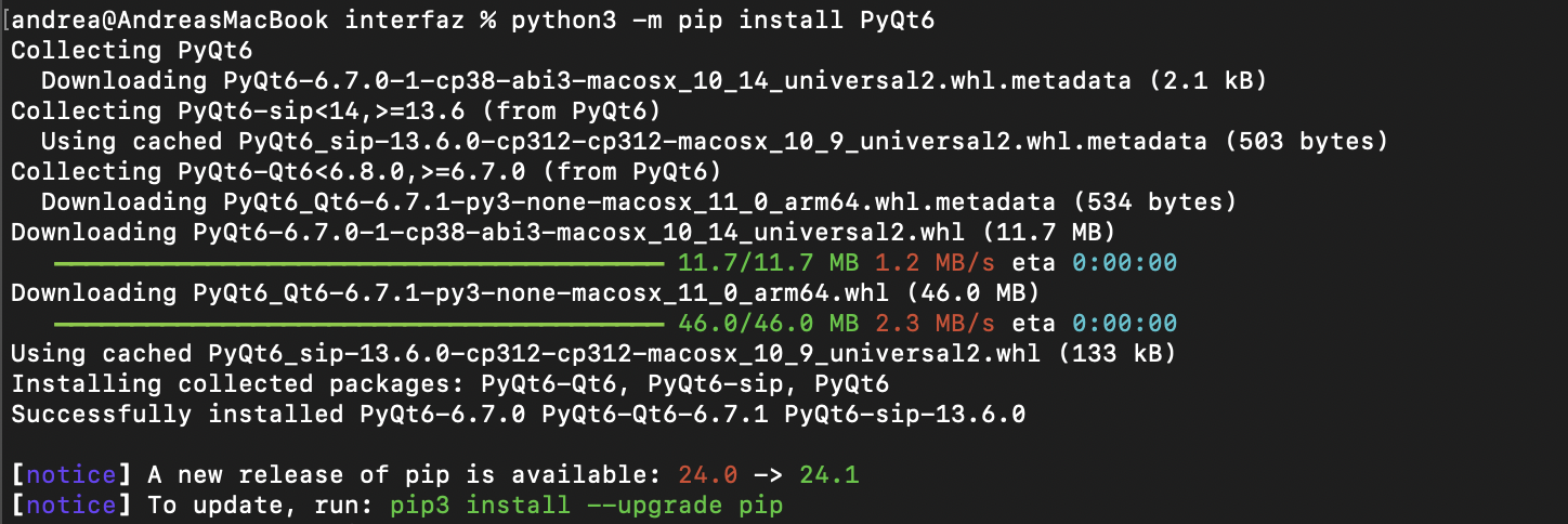
- Used the command cdin order to get inside the folder I had created and once in that folder I used the command python3 -m pip install PyQt6" to make sure Python was installed correctly.
- Converted the Qt interface file to a Python file using the command "pyuic6 -x interface.ui (name of my file) -o ui_interfaz.py (name of the new python file)".
- Then created an environment in the computer terminal using the command "Code ." which opened Visual Studio Code with all the information from Qt designer.
- Used the command cd in order to get inside the folder I had created and once in that folder I used the command python3 -m pip install PyQt6" to make sure Python was installed correctly.
- Converted the Qt interface file to a Python file using the command "pyuic6 -x interface.ui (name of my file) -o ui_interfaz.py (name of the new python file)".
- Opened Visual Studio Code and selected "Open" and selected my project's folder named "interface_oled".
3
Visual Studio Code
In Visual Studio Code I created a new page named app.py in which I pasted a code gave to us by our teacher Rafa.
CODE
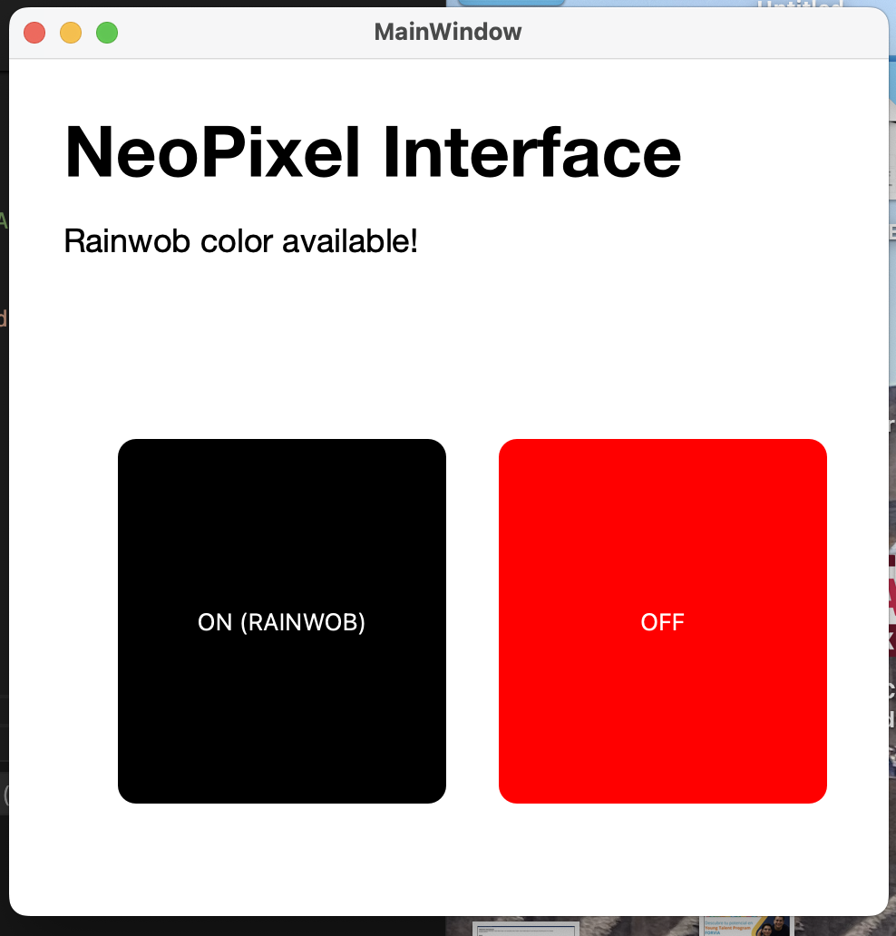
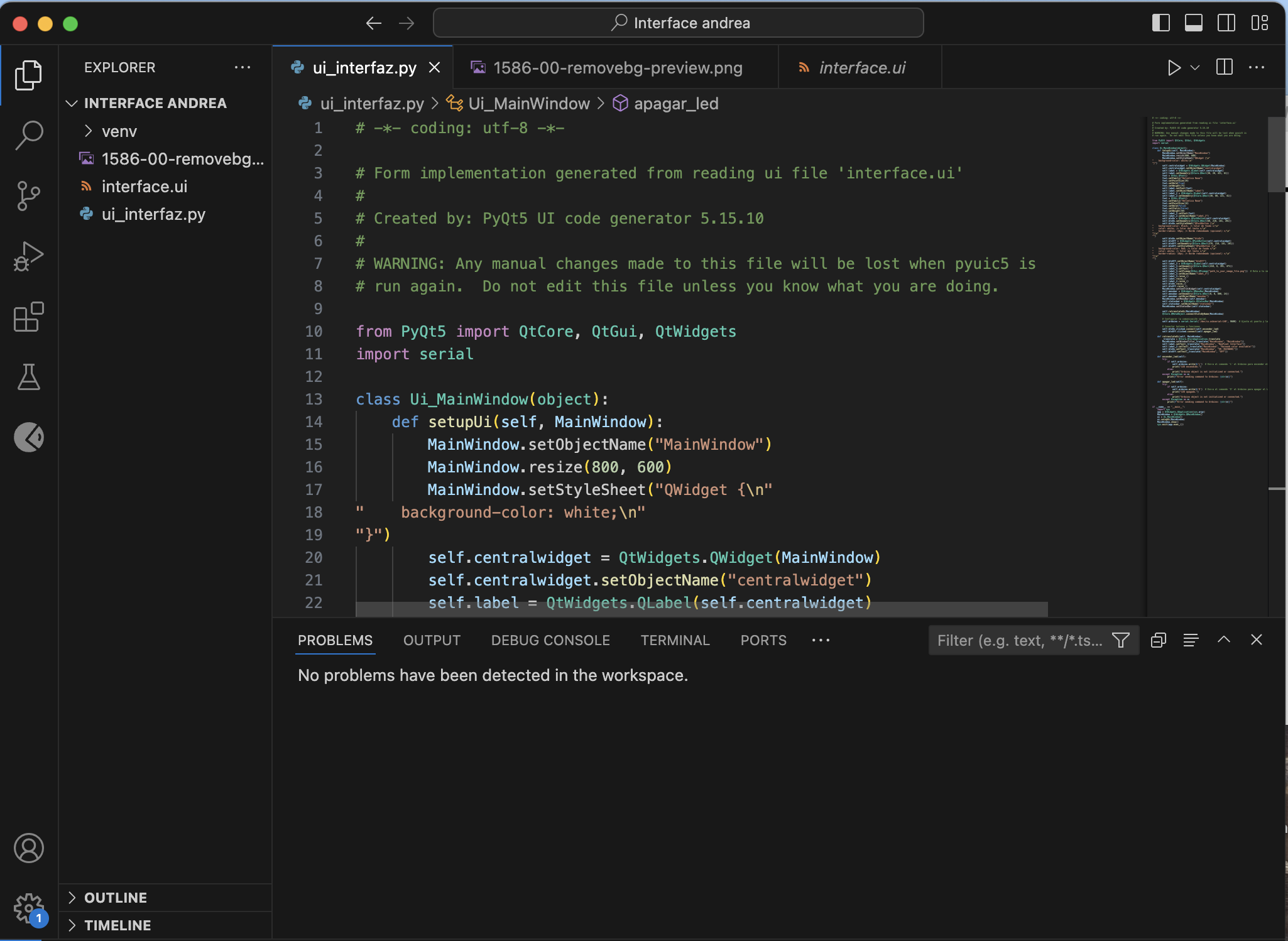
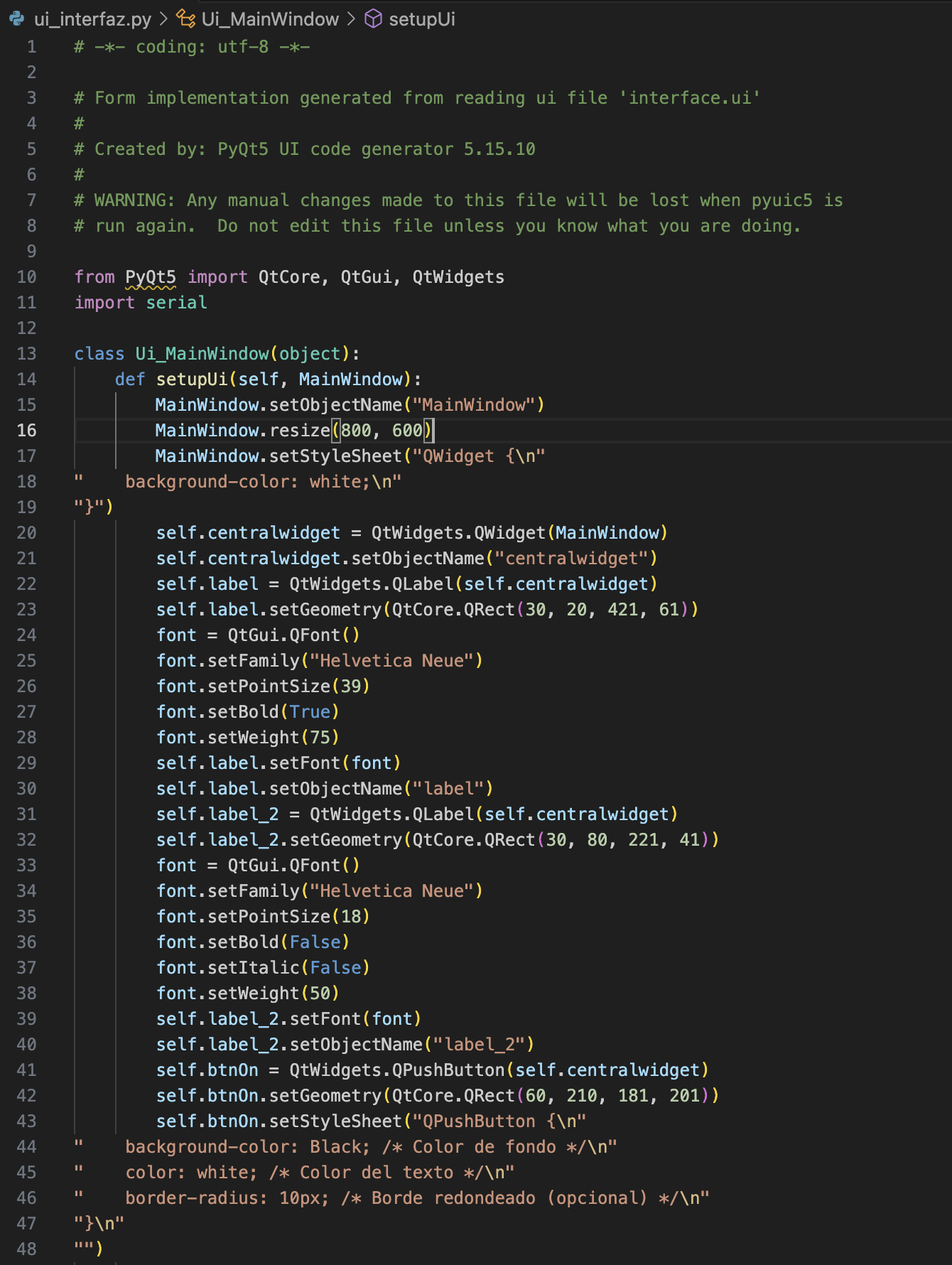
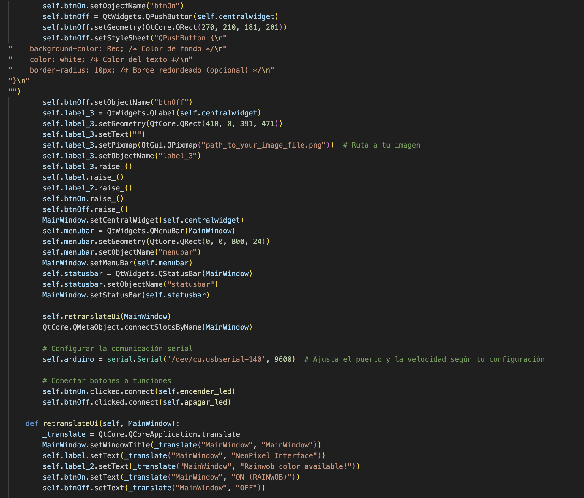
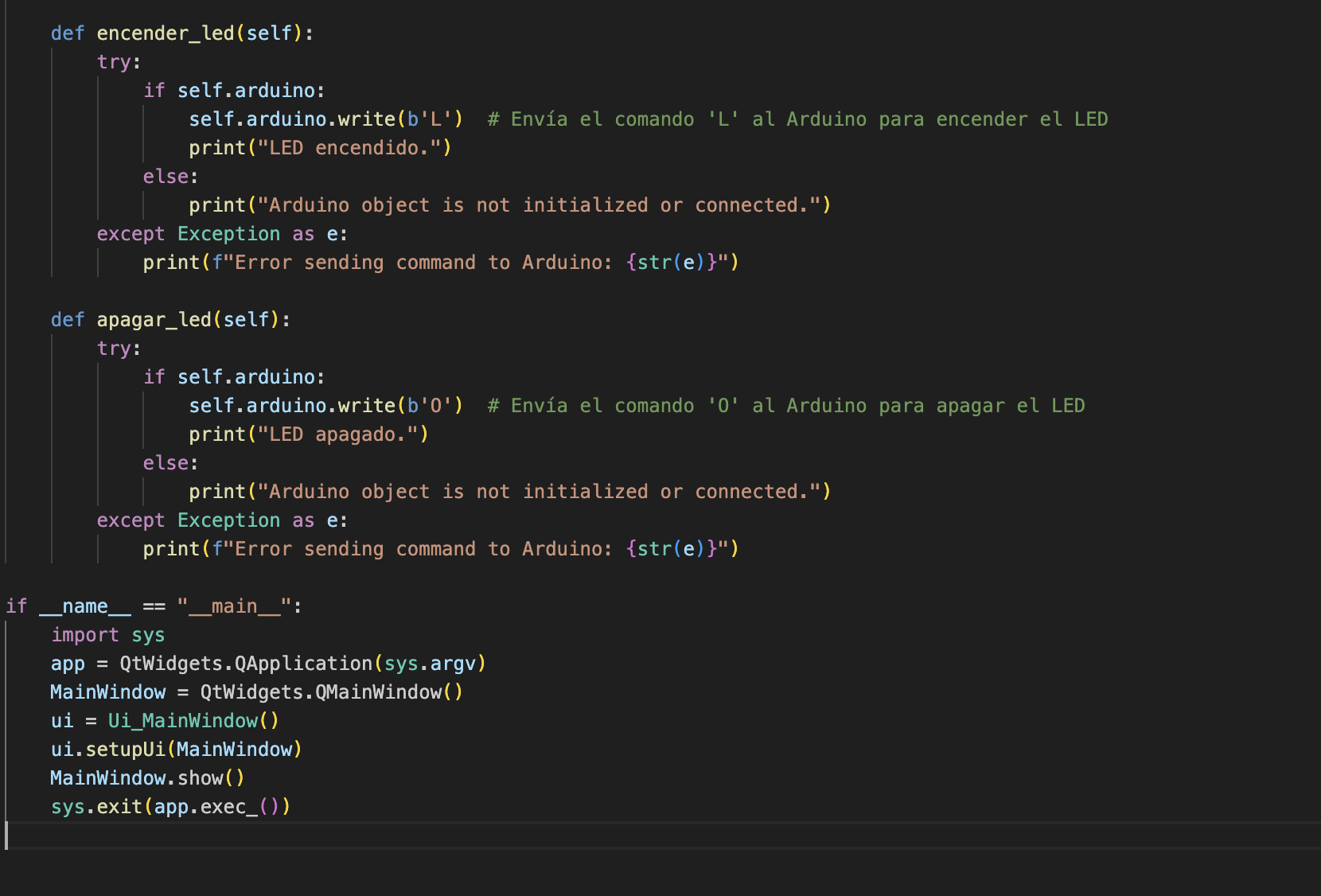
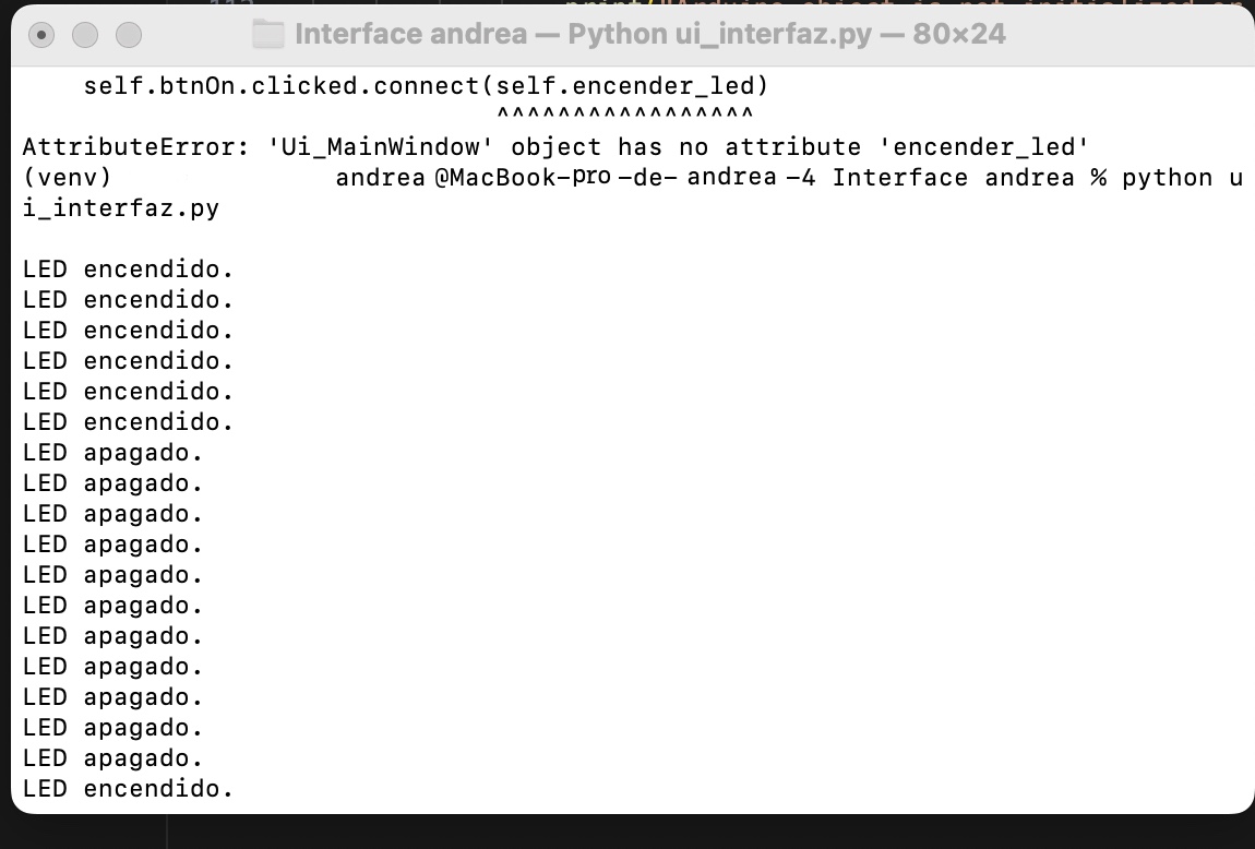
Then in the page ui_interfaz.py I adjusted the code so that the design for the interface would be correct and to make sure the buttons were labeled correctly and were going to turn on and off the ring of neopixels.
4
ARDUINO
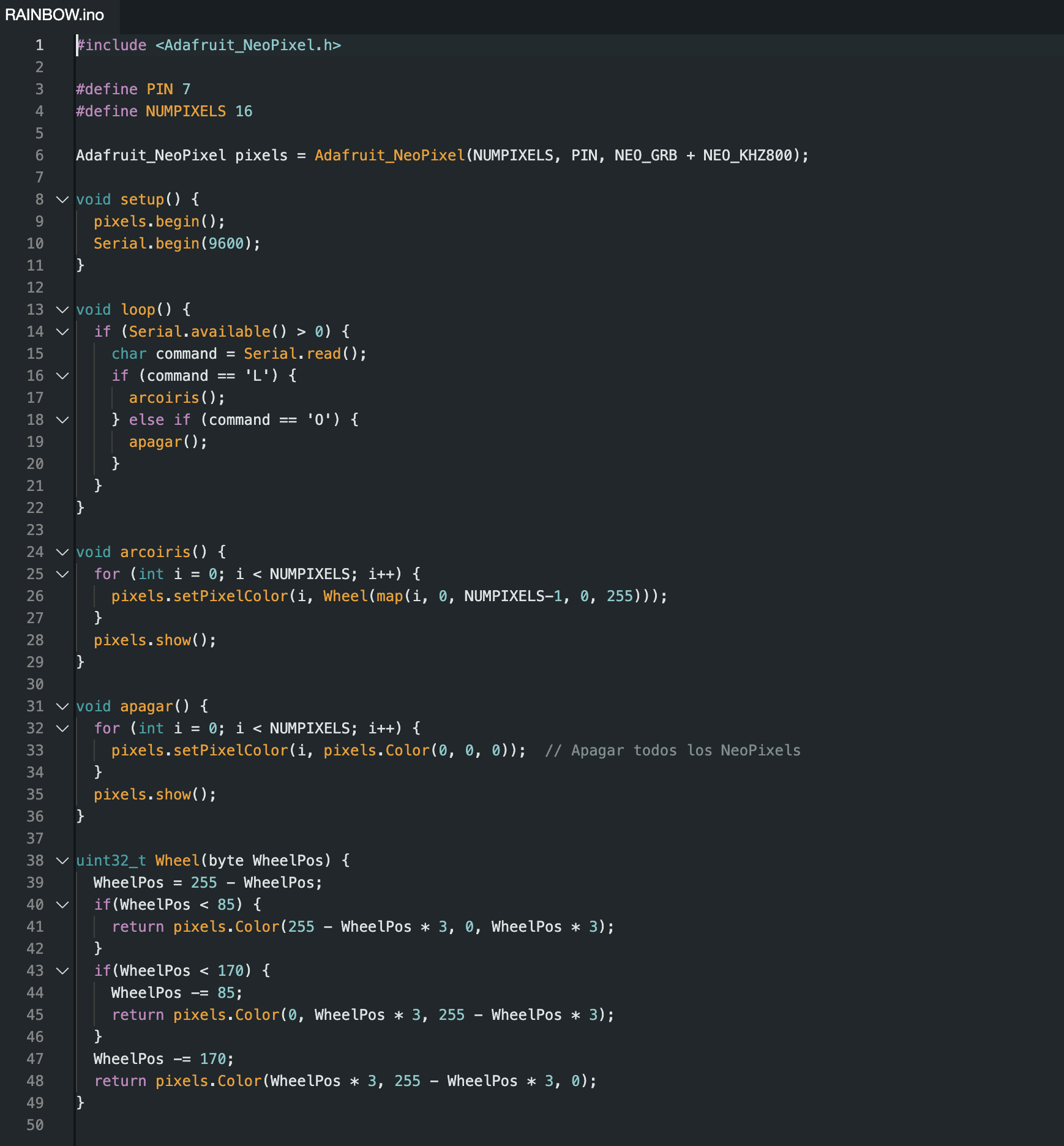
Then continued to create a file in Arduino IDE where I would programm the neopixel ring.
Testing
Once the code was finished I reopend Terminal and use the command cdto get into the interface folder and then executed the command source venv/bin/activateand then python app. py to visualize the interface. After this I opened the python code and made sure there was communication between the interface and the neopixel ring, which fortunately was succesful.
Result
Creating an interface with my own PCB!
I encountered some trouble with the NeoPixel ring as it stopped working, which was a setback in demonstrating how my own PCB works with the interface. Additionally, the previous code did not have the best communication. However, I decided to make the most of the situation and create a new interface, giving me further practice in the process.
QT Designer
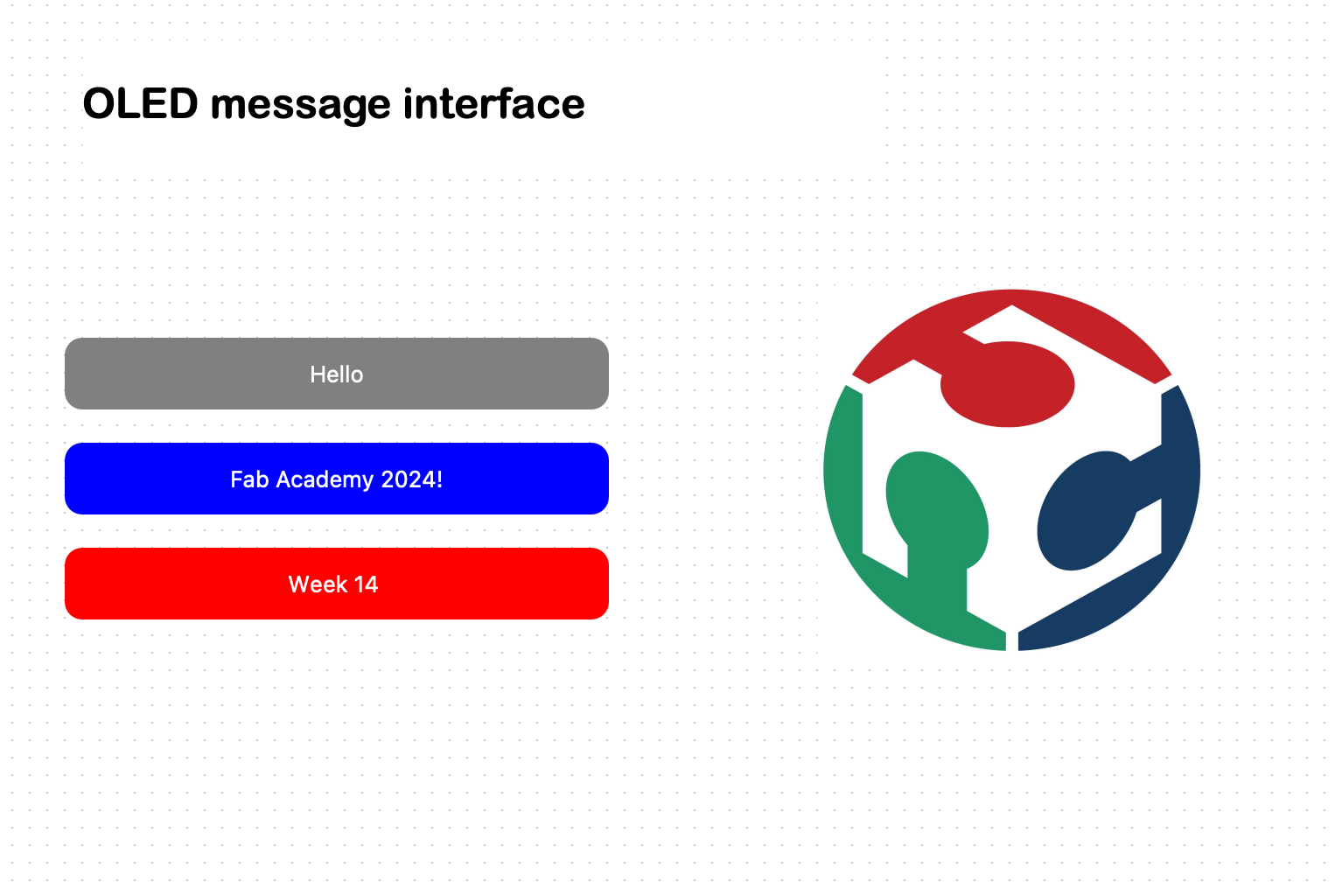
First I created a new project in QT designer in which I added three different buttons and correctly named them.
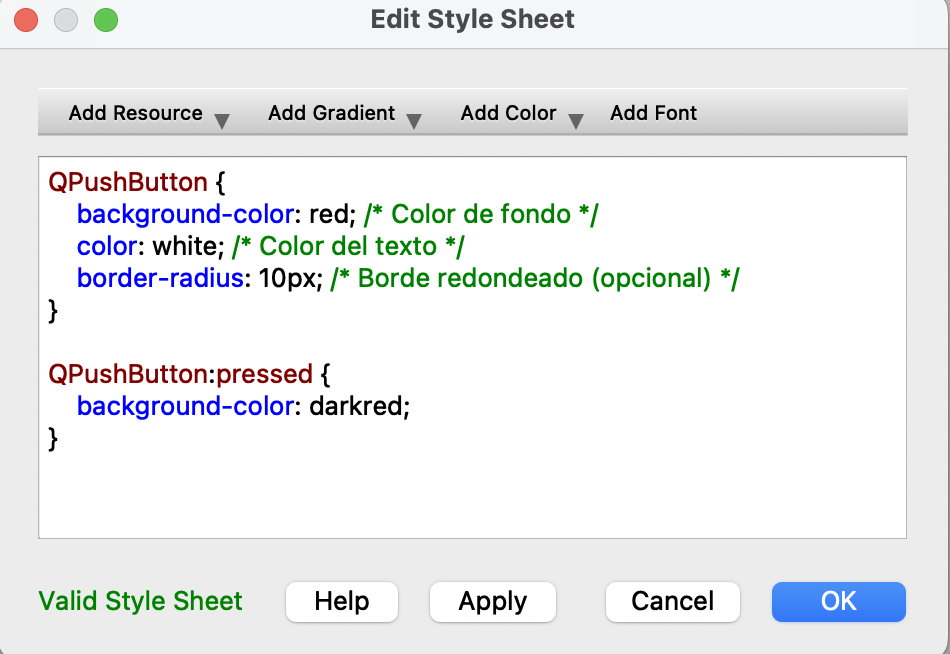
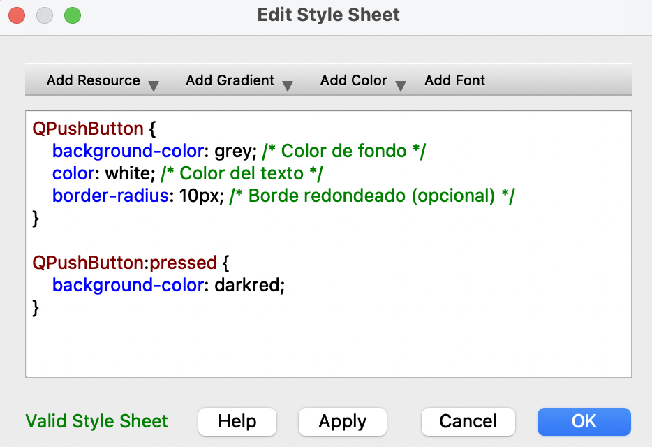
With two fingers click I changed the tyle data sheet so that I could select a background color and a different font.
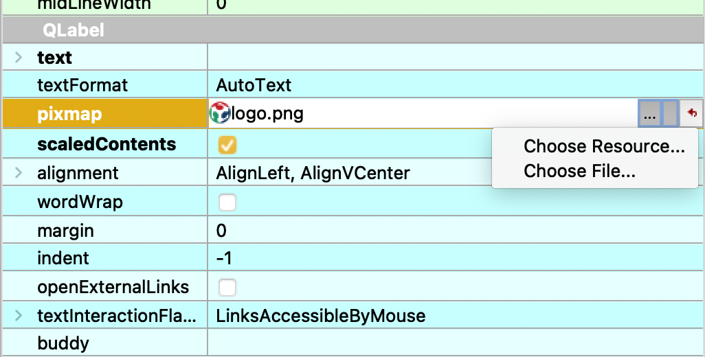
Then added a new label and in the right menu under "Qlabel" I selected "pixmap" and "Choose file". I made sure the wanted PNG image was saved in the same folder as the QT designer file.
Terminal
I followed the same steps as the previous interface:

Visual Studio Code
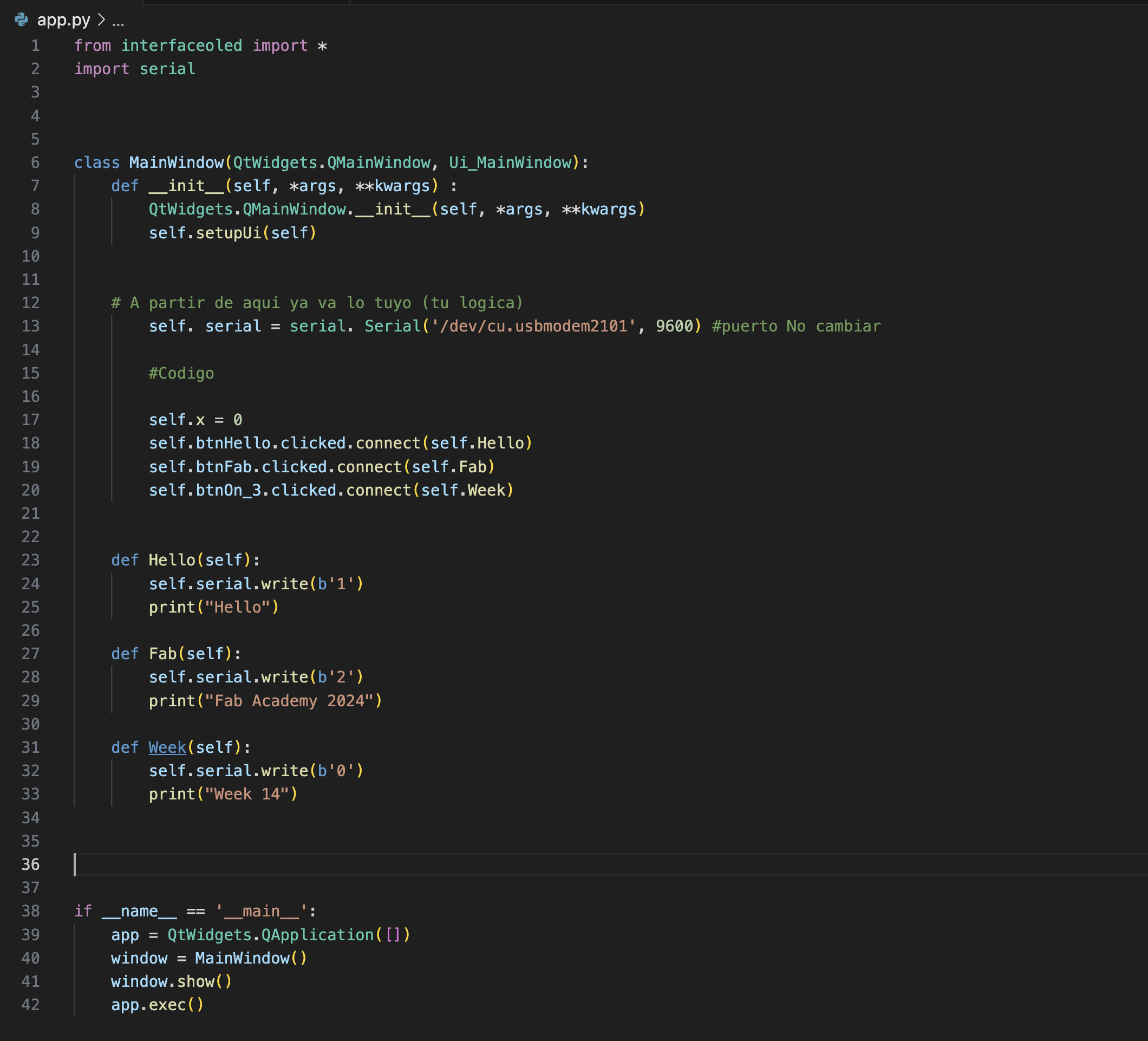
Created a new python file called app.py and pasted a code our teacher Rafa gave us.
from “THE NAME OF INTERFAZ” import * class MainWindow(QtWidgets.QMainWindow, Ui_MainWindow): def _init_(self, *args, **kwargs): QtWidgets.QMainWindow._init_(self, *args, **kwargs) self.setupUi(self) # From here, (your logic) if _name_ == '_main_': app = QtWidgets.QApplication([]) window = MainWindow() window.show() app.exec()
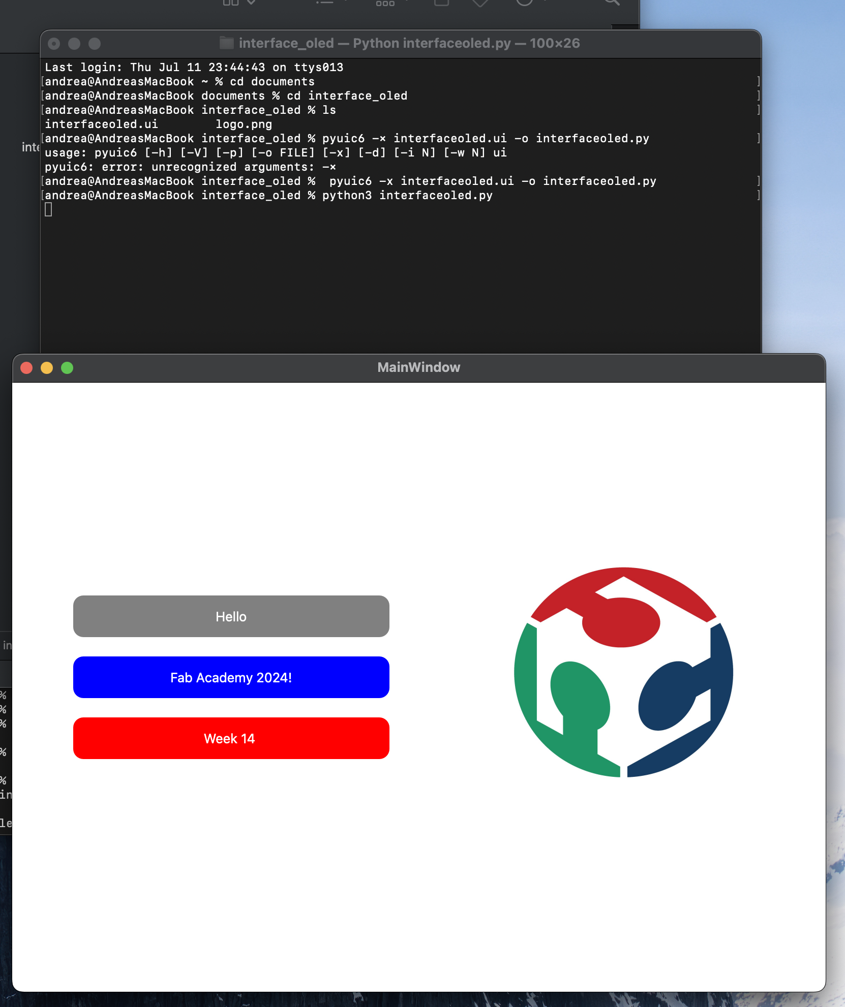
-Imported my interface's file and tried it in terminal using the command "python3 app.py"
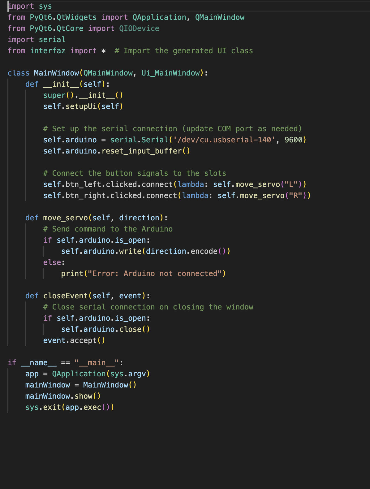
-Since it worked then I imported the Serial library
-Started by iniciating the serial communication "self.arduino = serial. Serial ('/dev/cu. usbserial-140', 9600)" to indicate the corret USB port that is going to be used.
-Then I defined my variables with the same names as in QT designer and started coding
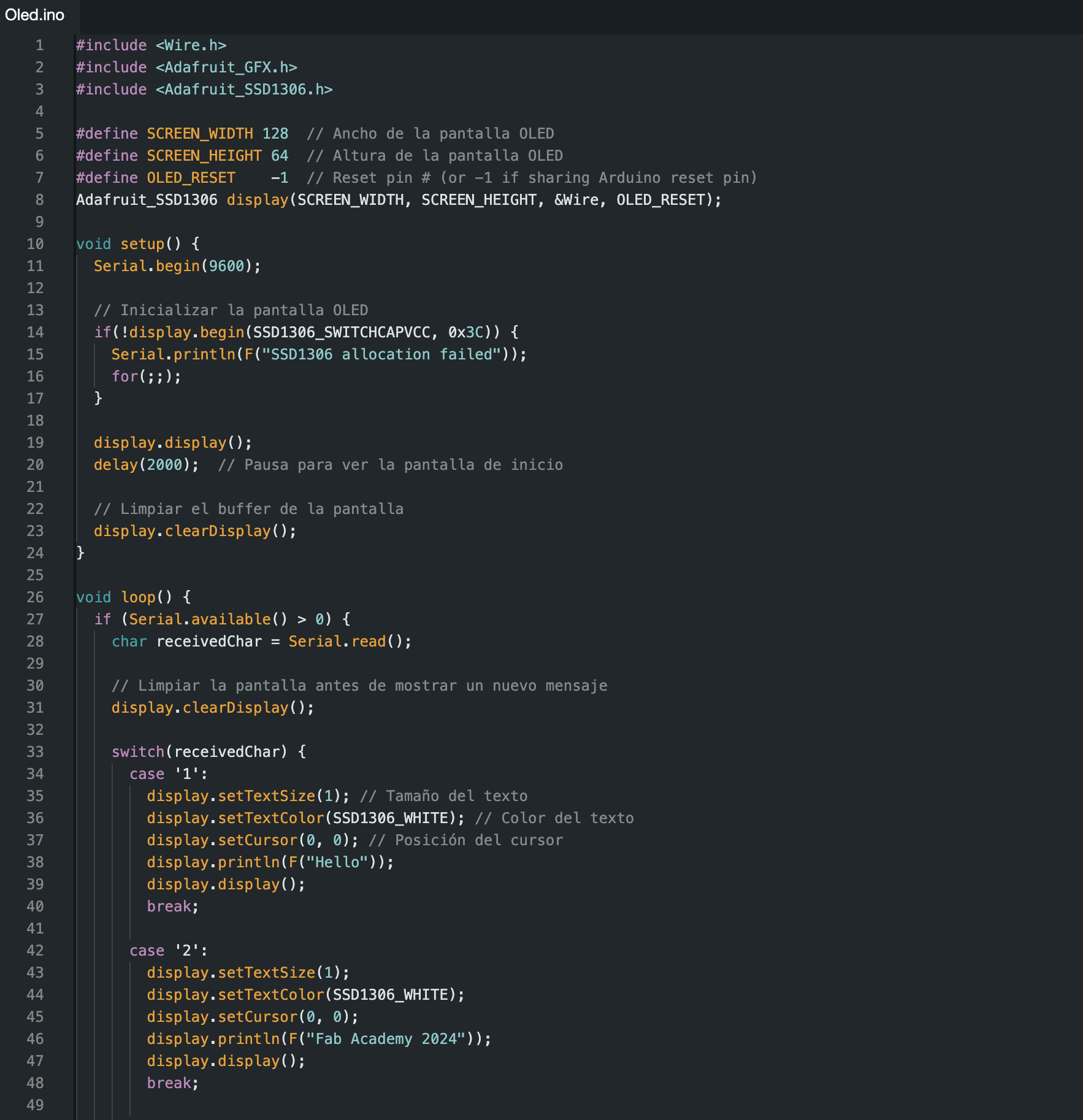
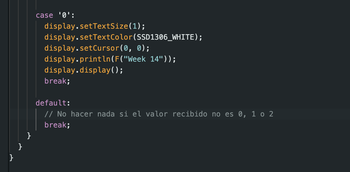
Arduino
Once that was done I created a new file in arduino and created a code in which when the button are pressed they send a message to the OLED to display certain message.
Firs, I tried the code with the Serial Monitor in Arduino IDE and since it worked I proceeded to test it through terminal using the command "python3 app.py"
Fourtunately, it all worked!
Communication
Once the code worked in Arduino I had to make sure that the communication between the interface and Terminal was workins so I used the command "python3 app.py" and tested the buttons in order to see if they correctly printed messages.
Communication between my PCB and the interface
Since the communication was working, I connected the OLED to my PCB and the computer and tested the interface. Fortunately, it worked perfectly! The communication essentially works in two ways. The first way is between the terminal and the interface, where every time a button is pushed, it sends a specific message to the terminal. The second way is between the Arduino and the Xiao RP2040; when the buttons are pushed, they send a message to the Xiao, prompting it to print a message.
A brief reflection on the assigment
This assignment was really helpful in understanding how interfaces work. One of the challenges I encountered was using the terminal, as many of the commands I initially tried didn't work. However, after restarting everything, it did! Using Qt Designer was easy and intuitive, and I found the software straightforward to use. Nonetheless, I would love to experiment with other software to explore more possibilities in visual design. Programming the NeoPixels was straightforward, but getting the interface and the NeoPixels to communicate took some time. Despite these challenges, I enjoyed this assignment.