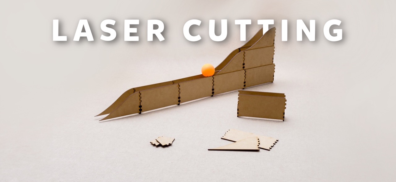
MODULAR PING PONG BALL TRACK!
For this weeks assigment I design a modular ping pong ball track that consists in 3 different pieces that interlock between them so you can make the track the length that you want. It has so many ways in which you can arrange the track so that in never gets boring!
Laser Cutting 101: A Beginner's Guide
What's Laser Cutting Anyway?
Imagine a very precise and powerful light scissors, so strong that it can cut through materials like paper, wood, plastic, and even metal. This light beam is produced by a machine known as a laser cutter. Laser stands for Light Amplification by Stimulated Emission of Radiation. It works by focusing a high-powered laser beam onto a material which it either melts, burns, or vaporizes away, leaving a very sharp edge and precise cut.
How does a Co2 Ray cutter work?
For this weeks assigment I learned how to operate a Co2 Ray, it basically relies on a high-pressure gas-filled tube with mirrors at each end. These mirrors reflect the light generated by the CO2, amplifying the beam of light. When the light reaches the desired intensity level, you simply direct it onto your chosen material.
Turning on the Laser Cutter
Here's a handy tip to power up the machine: start from the bottom and work your way up.
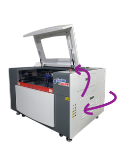
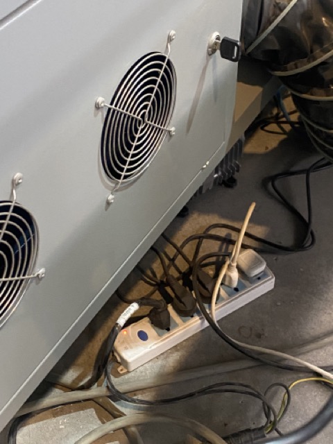

- Flip the main switch to turn on the machine
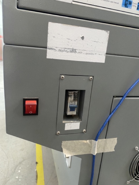
- Hit the red switch next
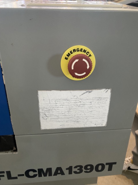
- Disengage the "oh no!" (emergency stop) button
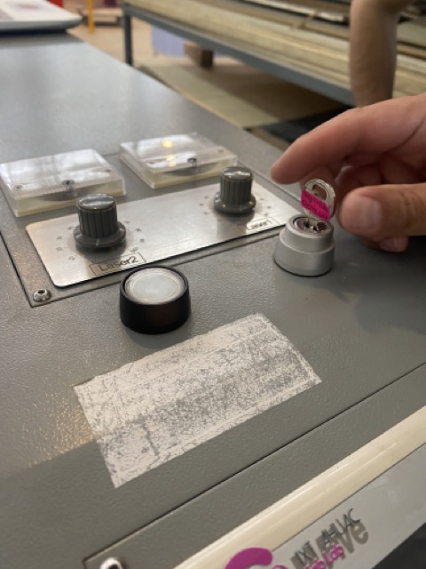
- Turn the key to ignite
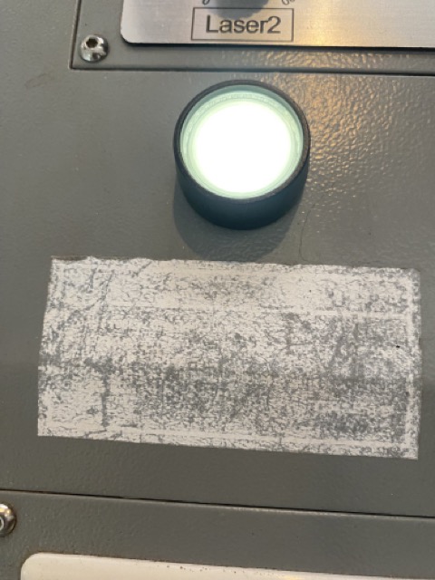
- Hit the white button
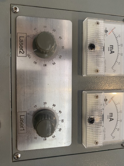
- Set the laser power. I usually turned the laser power to 100% and adjust it via computer
- Once you imported your document you should change the origin in the laser cutter by moving the arrows manually to choose the starting point of the laser (if you are not sure the laser is located where you want it to be you can always do a push which means the laser with cut a dot in the place it is)
Smart Carve 4
Smart Carve 4 is a software tool used for laser cutting and engraving. It provides a user-friendly interface for designing and controlling laser cutting machines. With Smart Carve 4, users can import and create designs, adjust cutting parameters, and control the precision and speed of the laser.
Other softwares that could be used instead of Smart Carve 4 could be:
- Lightburn
- RDworks
- EZCAD
- LaserGRBL
- Trotec JobControl
- Epilog Laser Dashboard
- Universal Laser Systems (ULS) Control Panel
Each laser cutter manufacturer typically provides or recommends software that is compatible with their machines. In this case, the software that is downloaded in the computers of the laser cutter is Smart Carve 4 and that is the licence that the University has, so that is why I used it for the assigment.
Importing your document to Smart Carve 4
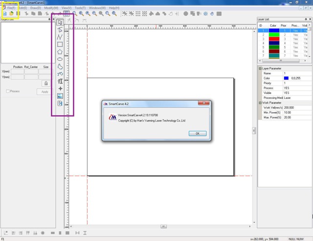
- Open Smart Carve 4 on your computer
- Click the file menu that is located on the top left of the window
- Then select the import option
- Once your document is imported you can scale, rotate and move it with the tool panel on the left side of the screen (It is a very intuitive software but I actually only moved the vectors)
- Finally you have to choose the power and speed to start cutting. As a group we cut a document with different powers and speeds to get to know how the laser machine cuts. If you dont know what to choose I recomend you do this exercise to get to know your machine. I´ll leave a great tutorial on how to test it Youtube's tutorial
- I used the 20 mm/s speed and 50.0%/50.0%
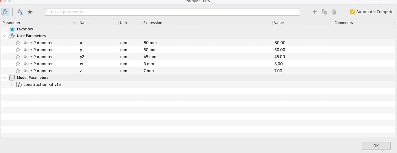
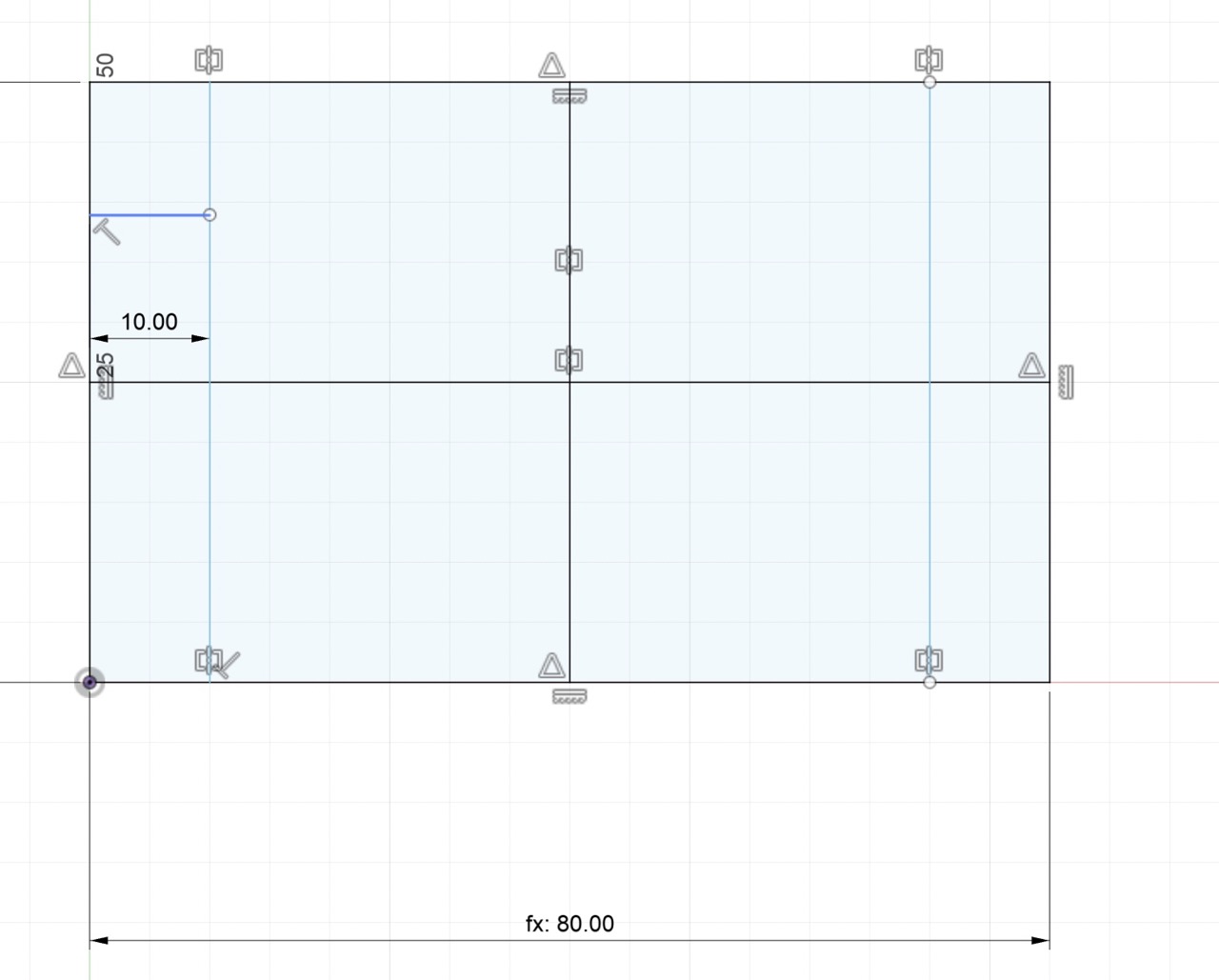
Making sure your design is parametric
I used fusion 360 to sketch my design, to keep things flexible (parametric), I set up parameters, this trick allows for easy tweaks down the line. First of all you have to analize your design and identify how to translate the meassurements into parameters. Some tips that I discovered throughout experimenting with a parametric software are:
- Determine the meassurements of your design
- Make sure the meassurements fit within each other (if you want the pieces to fit perfectly it is easier if you choose numbers that are multiples of each other. For instance, you could make the height half the length like I did for this project)
- Before sketching in a computer software I recommend sketching your idea on an Ipad or paper to make sure you understand the shapes you are proposing
- Analize which meassurements depend on others. For example, if you want to make the "join" the size of the width of the material, you could create a parameter for the Width of the material: x and another for the join: y so if you were to change the width of the material you can later change the design! Including the parameter join leaves you room to later add the offset directly on the parameter.
How I sketched in Fusion 360
- First of all I sketch my idea on the ipad to make sure I understood how the pieces were supposed to fit within each other (I find it very useful to have a detail sketch before venturing into a computer software)
- Then I proceded to create parameters
- I used the line feature to sketch the three different pieces using the parameters as meassurements
- The pieces were a snug fit but loosening the Kerf to .05 would make the assembly smoother.
- After assembling, I noticed the potential for curves but spotted gaps between the pieces so designing a filler piece could up the versatility or even a flexible curve to make it more interactive.
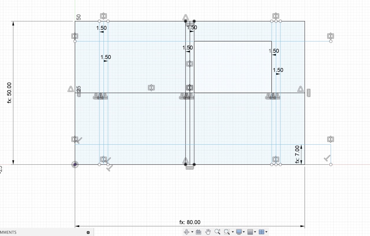
- First I created the parameters
- Created a new sketch
- Sketched the piece with the parameters previously set
- Gave the joints a .1 mm ofsset (since the kerf is .19)
- Copy and pasted the piece 3 times and added some shapes for an asthetic finish
- Exported the sketch as a DXF
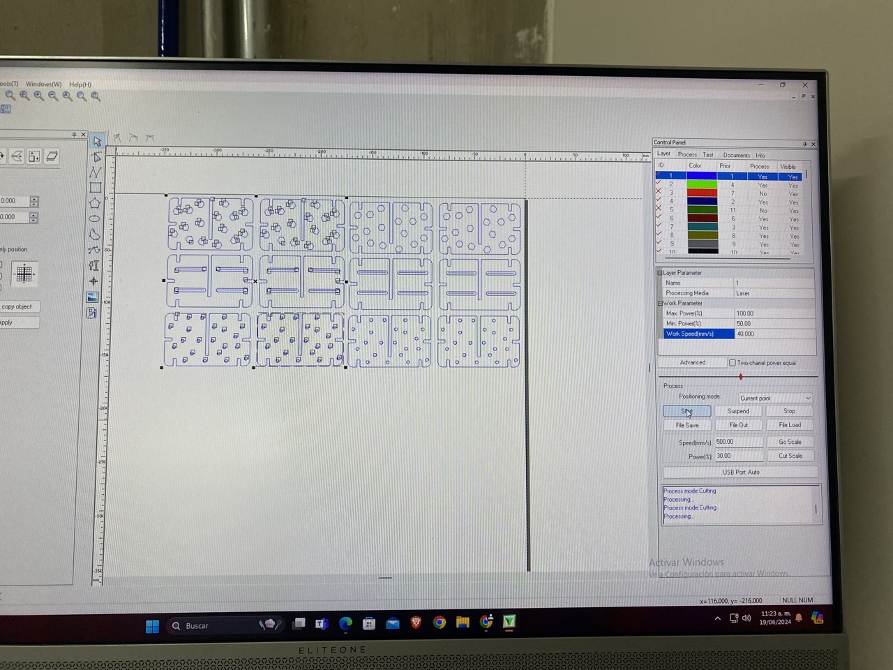
- I imported the DXF file
- Organized the different pieces
- Set Max. Power to 100%, the Min. Power to 50% and the Work Speed to 50 mm/s
- Turned the laser cutter ON and clicked on START
- Download the Silhouette Studio which is the software for the vinyl cutter
- Opened the PNG file
- Arranged the png and made sure the scale was correct
- Placed the vinyl paper on the machine
- Sent my file to be cut
- Removed the cut
- Weeded the design
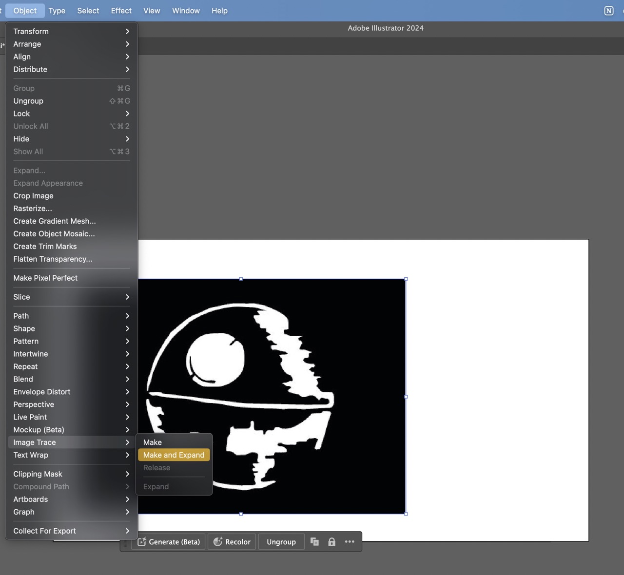
- First I imported the image in Illustrator
- Then in the general menu, under the object menu I selected "Image Trace"
- Clicked on "Make and Expand"
- It is necessary to select the "Ungroup" option to be able to manipulate the traces
- Selected the traces with the "Direct Selection" which is the white arrow
- With the "Smooth Pen" corrected the form
- I followed the same steps for every spaceship
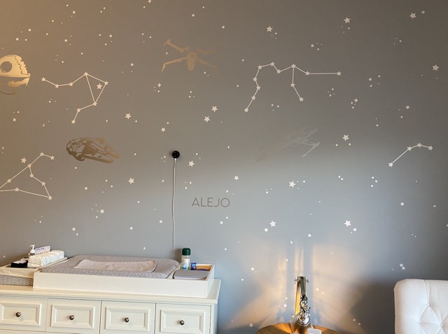
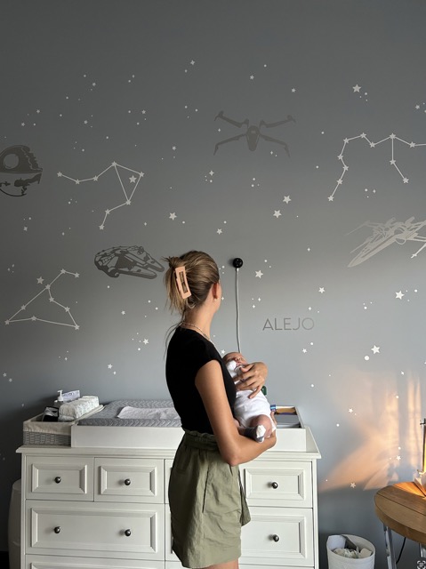
- Once the vinyl was cutted I proceeded to weed it and pasted it on the walls with the help of my sister
- Make sure what materials can be cut in your laser cutter
- Test the Kerf
- Do a test of speed/ power of the cutter
- Make sure you have meassured the right width
- Make a 1/2 of the Kerf value offset to the joints
- Identify which parts of the piece need kerf and which doesn't
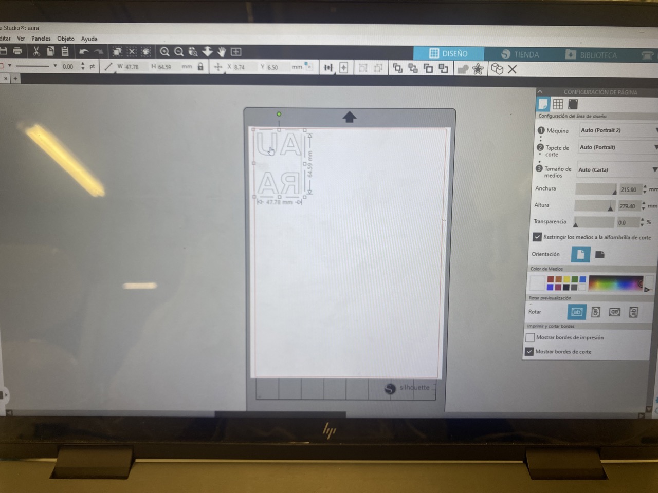
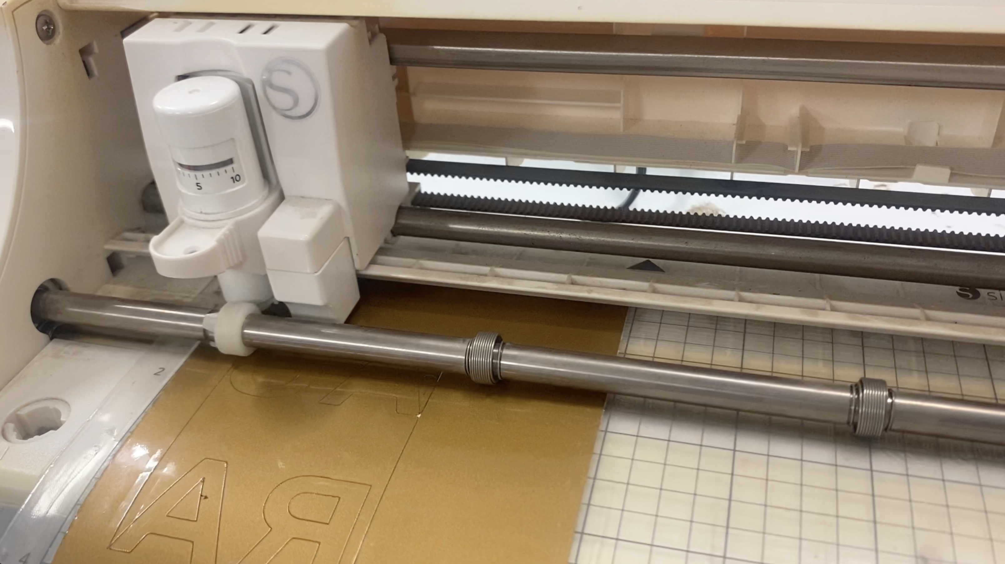
- First I added the DFX file that I wanted to cut, in this case it was my final project´s logo.
- Then pressing shift I changed the size of the logo
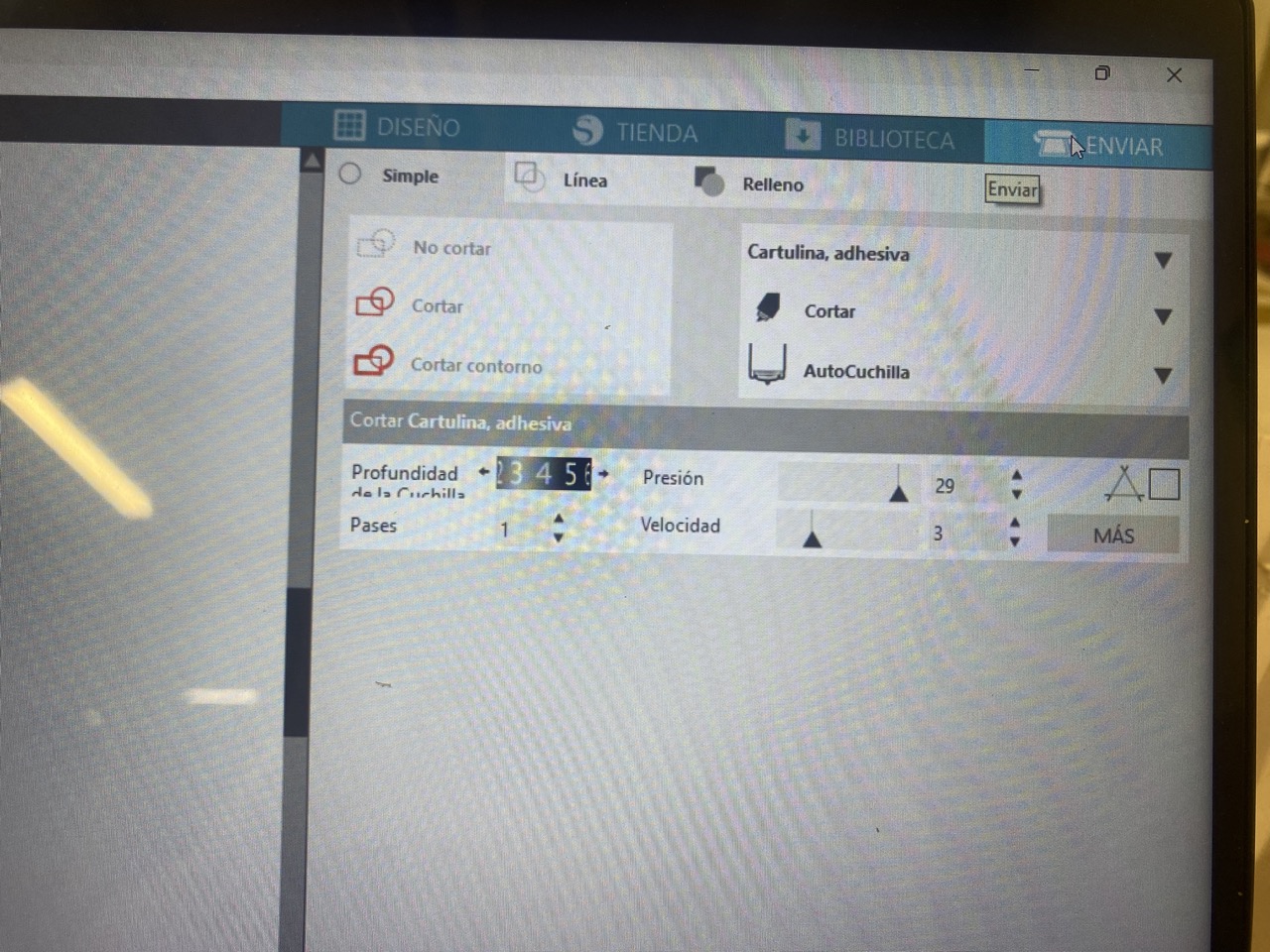
- Proceeded to click on the "send" menu and selected "cut outline"
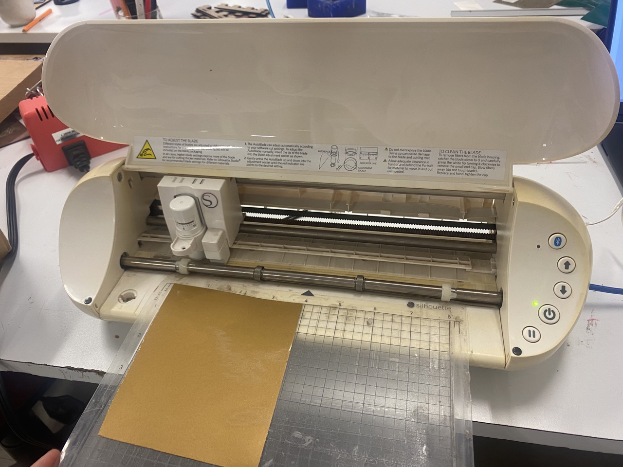
- Pasted a piece of vynil paper into the plastic sheet and using the up narrow inserted the plastic paper
- Finally clicked "send"
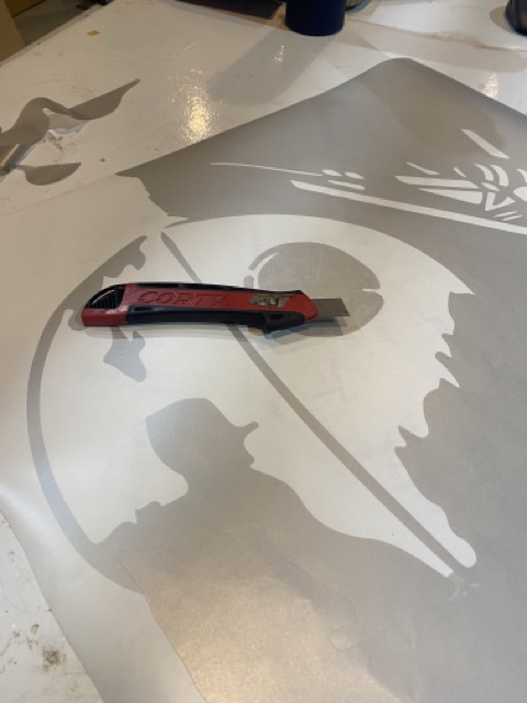
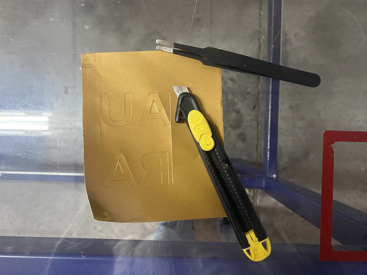
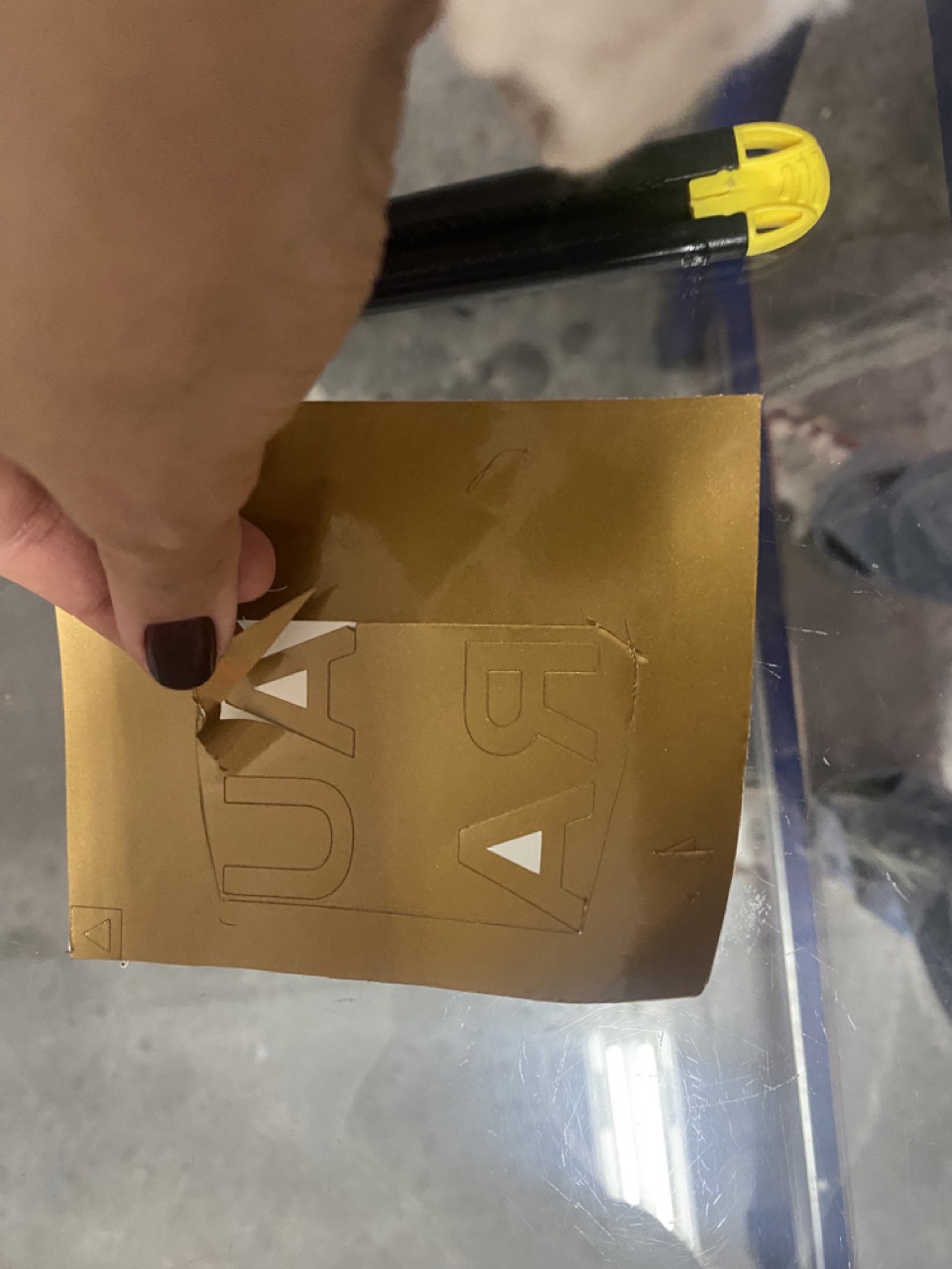
- With a fine cutter remove all the vynil that is not needed only leaving the shape you want to transfer
- Take a piece of transfer paper and paste the vynil cut on it and cut around it
- Make sure the cut is pasted correctly into the transfer paper and carefully remvove the transfer paper
- Paste the transfer paper into the wanted space for the cut
| Name | Description | Meassurements |
|---|---|---|
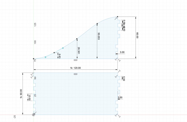
| Length Base (Lb) | being the length of the base piece | 120 mm |
| Height Base (Hb) | being the height of the base piece | 60 mm |
| Joint (Joint) | being the depth of the joints | 5 mm |
| Width material (Wm) | being the width of the MDF that I used | 3 mm |
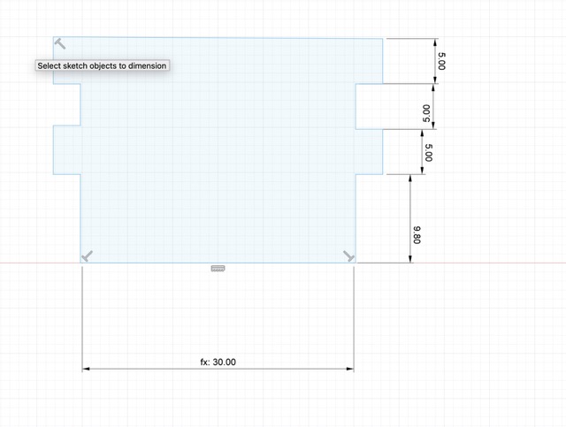
| Height Union (Hu) | being the height of the smaller piece that serves as an union piece | 25 mm |
| Length Union (Lu) | being the length of the union piece | 30 mm |
| Kerf (kerf) | specifying the kerf to later use this number in another parameter | .1 mm |
| Width material with kerf (Wmk) | making an addition with the materiak width and the kerf | 3 mm + kerf (.1mm) |
I´ll leave a photo of the design with the meassurement in case you later want to recreate it

Understanding the Kerf!
Kerf's all about the laser's cut width. When you tell the cutter laser to follow a vector shape it cuts withing the established line but also a bit out and inside of it. This may not seem like a big problem but when you intend the pieces to fit within each other the won´t!
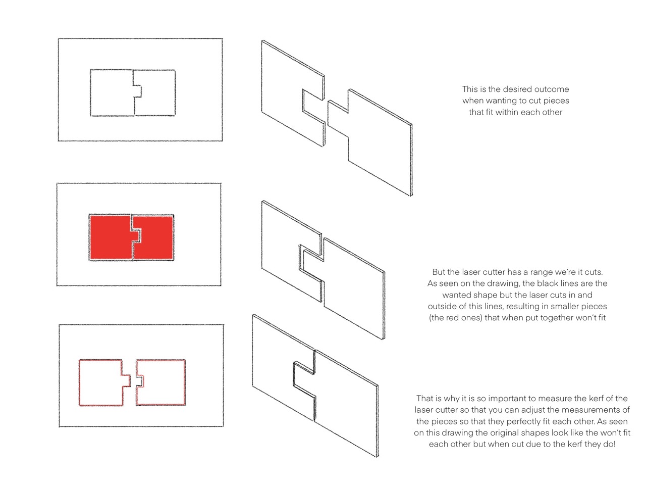
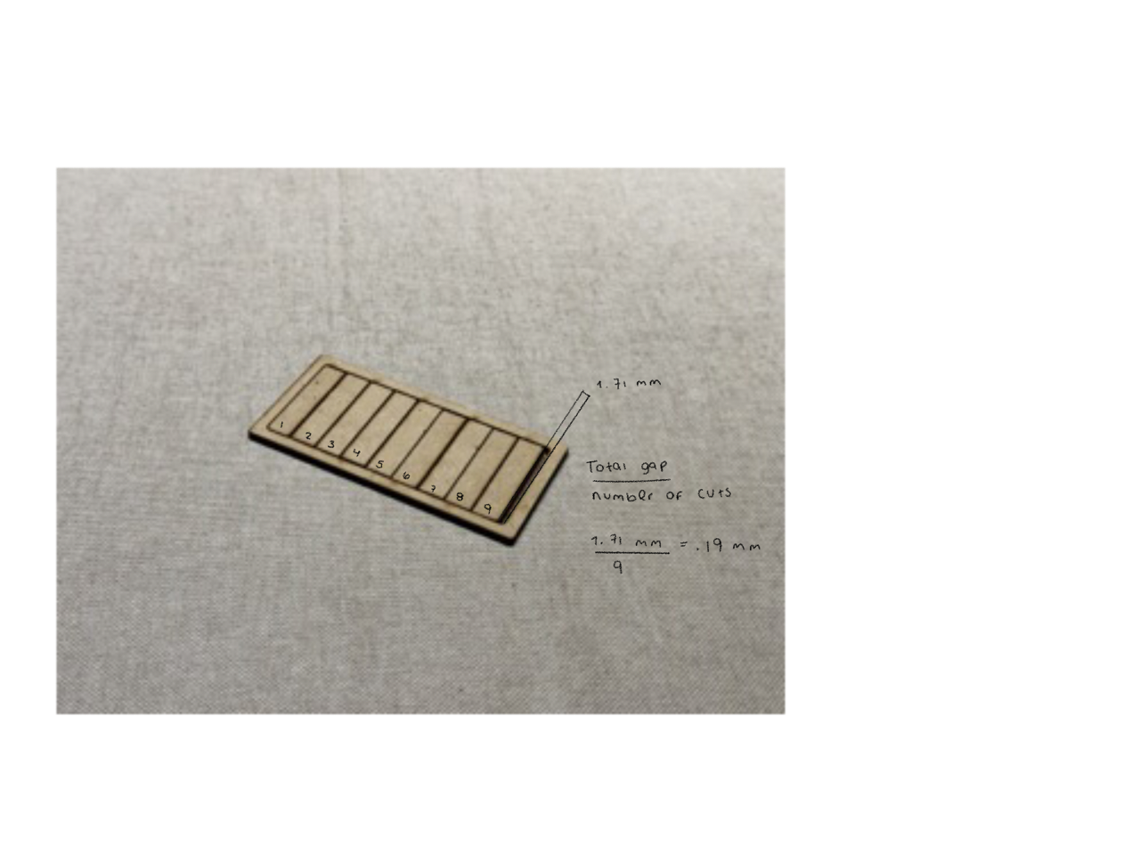
Every laser cutter has a different Kerf because it depends on several factors such as material, shape, assist gas, beam power, among others. I figured mine out by cutting several rectangles inside a frame, pushing them together, measuring the total gap, and dividing that by the number of cuts (I used 9 cuts to make the total of the rectangules 10) this gave me a kerf of .19 mm.This is handy for precision.
Group's Assigment
For this weeks group's assigment our teacher explained us the safety meassures that are necessary to use the laser cutting machine. They also gave us a list of materials that can be cut and important parameters to keep in mind befor using the machine. This was very helpful and insired me to do my own kerf test just to learn how to calculate it.
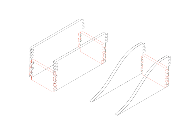
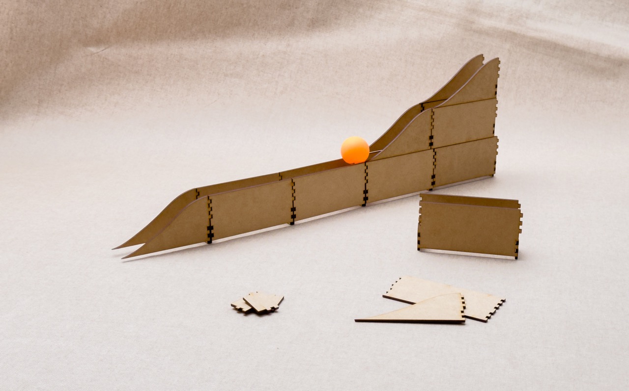
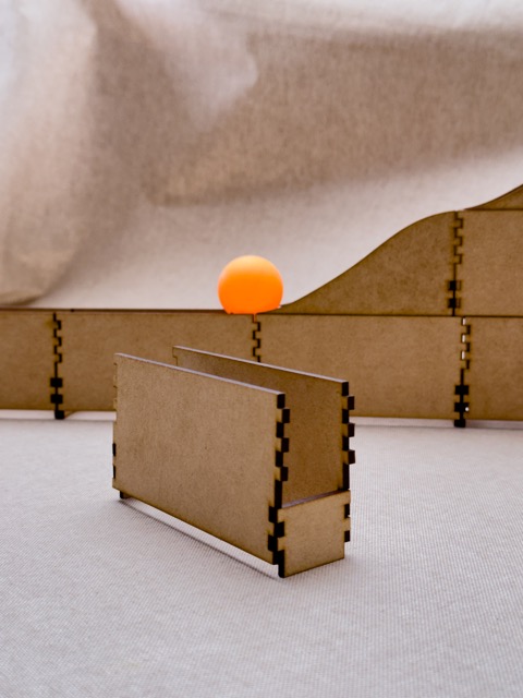
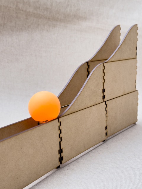
Project : Modular Ping Pong Ball Track
This week, I designed a modular ping pong ball track with three interlocking pieces, forming two types of modules. One allows stacking for height, and the other creates slide effects. It's like LEGO for ping pong balls, letting you build your own tracks. It has multiple ways to build it which makes it more fun! The track consists in 3 different pieces : the base piece wich is used to create the length of the track, the union piece that functions as a joining piece for the base pieces and the slide ones and the slide piece that creates a little slide also using the union pieces. It is design as modules since each one of this needs 4 pieces. The design makes it possible for the base pieces to fit within each other so you can make the track the length that you want. To create height the modules fit on top of each other thanks to the union pieces, since these work as a stop so that the top module does not move.
Improvements that can be made
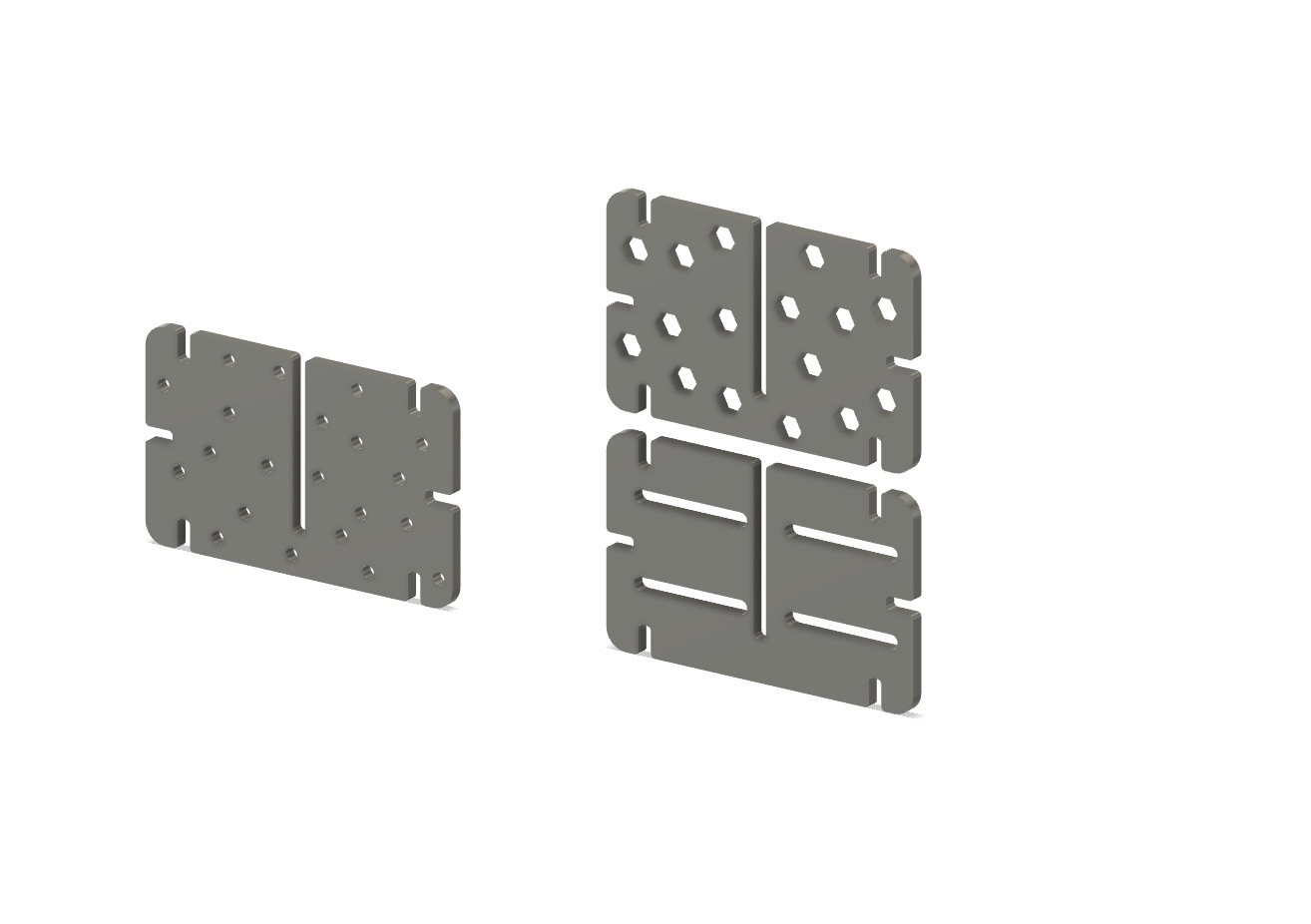
Contruction Kit
Even though I really liked the MODULAR PING PONG BALL TRACK, it had a limitation in the number of ways it could be assembled. That's why I decided to design a construction kit to showcase the possibilities of laser cutting and the use of kerf. After some brainstorming, I decided to create a kit that consists of only one piece. This approach was both interesting and challenging, but I felt it was a great way to apply what I had learned about laser cutting. First, I sketched the idea in Procreate.
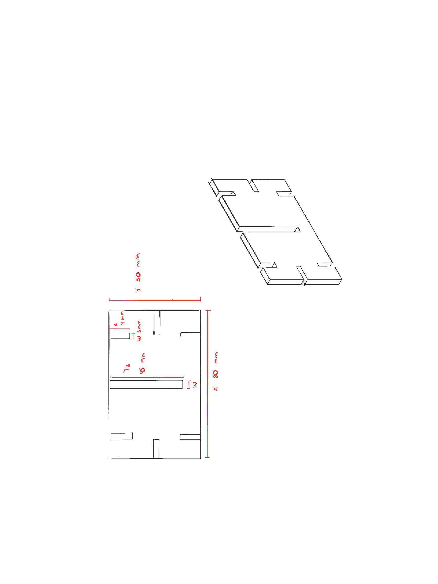
Then proceeded to model it on Fusion 360
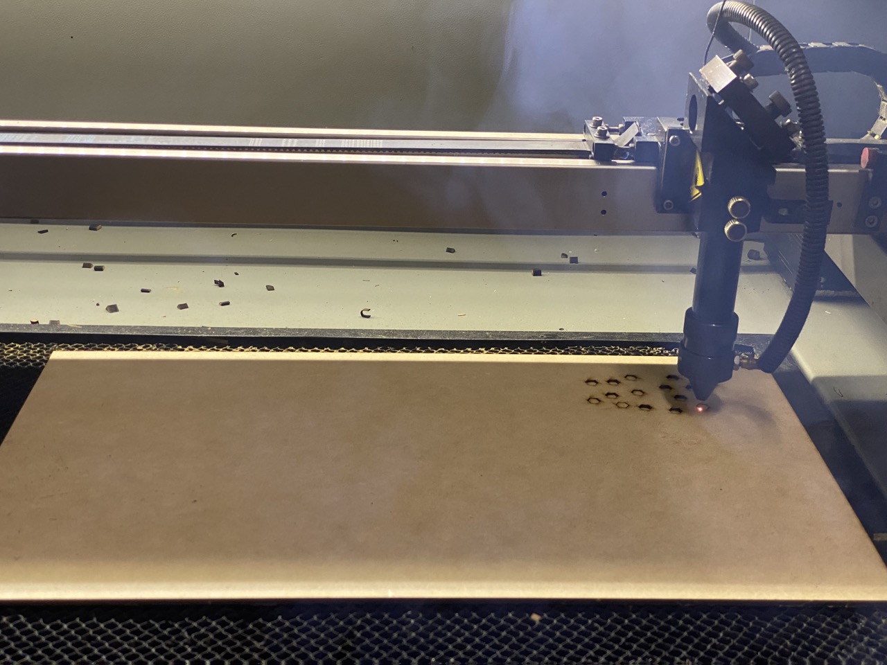
Laser cutting the construction kit
I followed the same steps as for the Modular Ping Pong Track. I set the Max. Power % to 100, the Min. Power % to 50 and the Work Speed (mm/s) to 50. This gave me a clean cut.
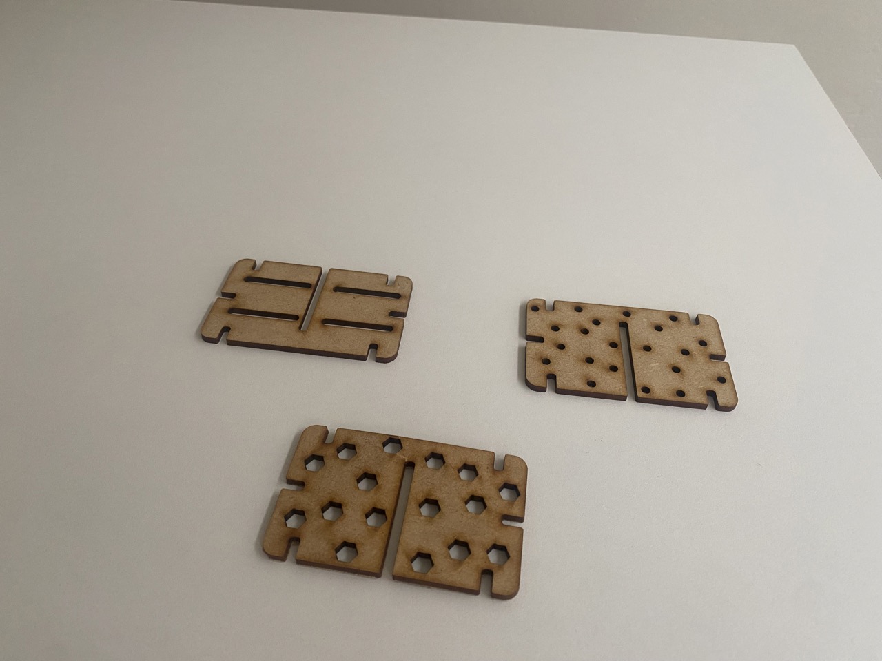
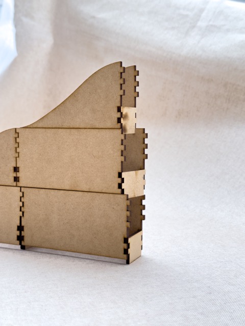
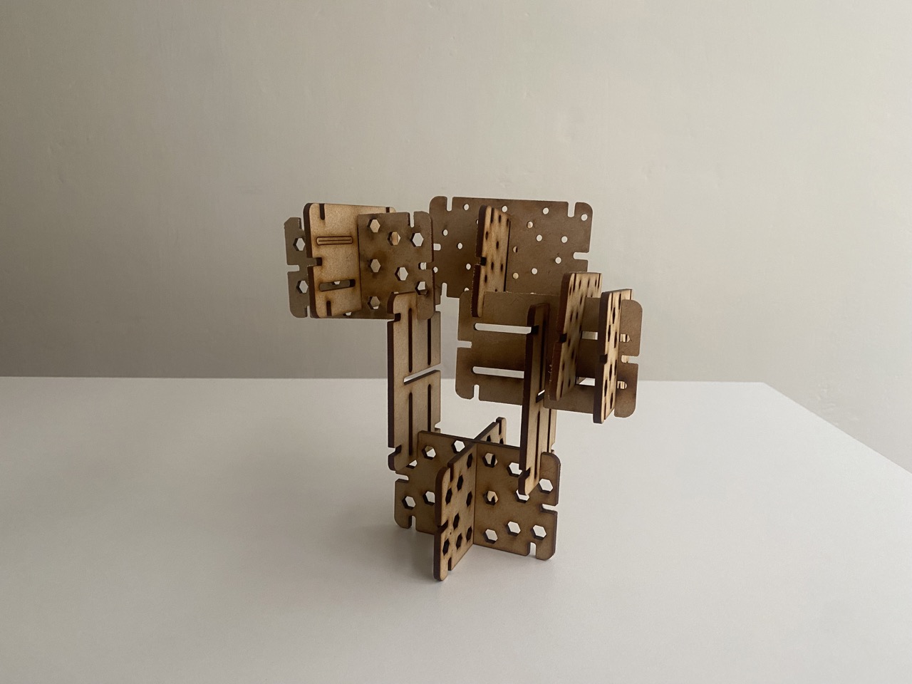
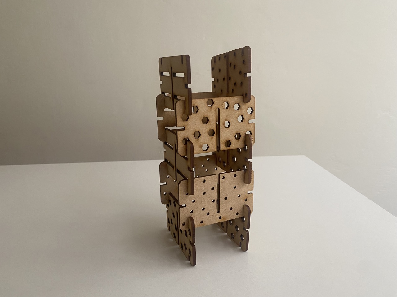
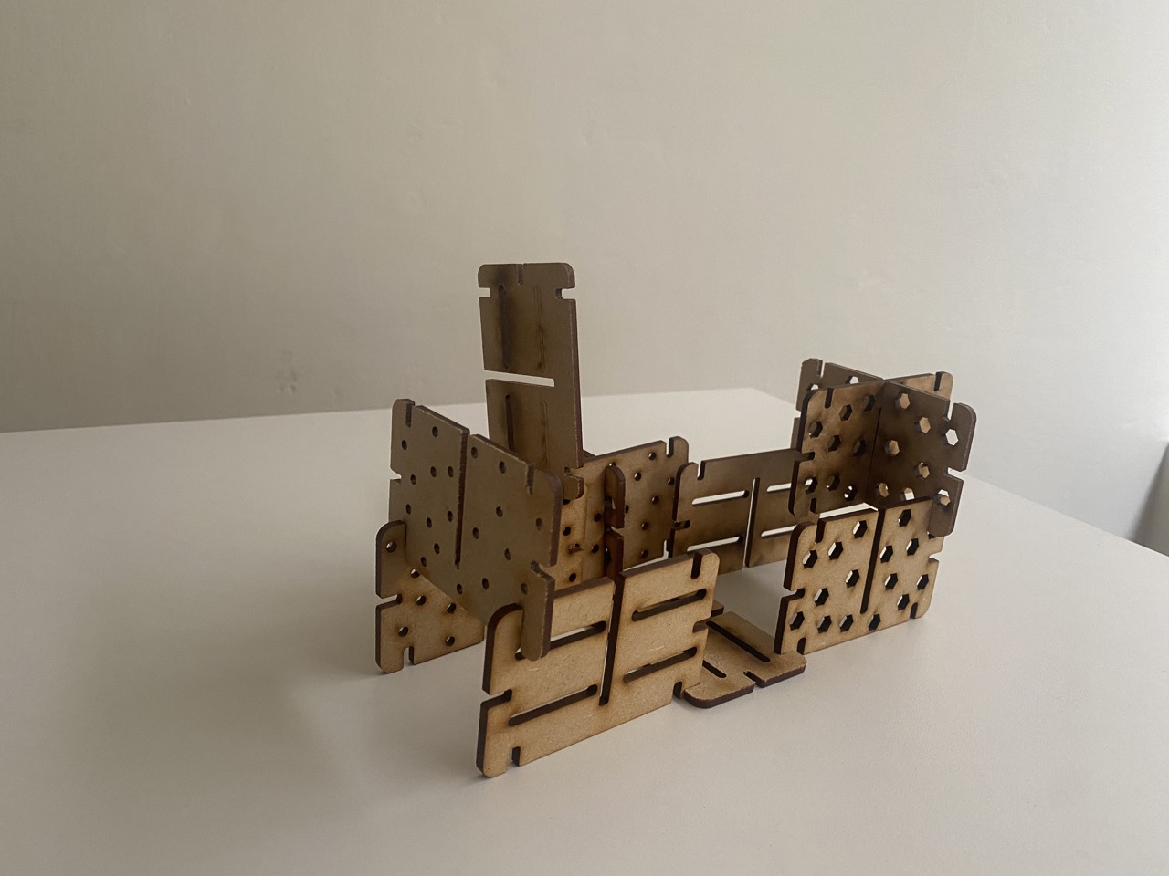
Construction Kit
This construction kit was designed to be assembled in various ways, making the building process enjoyable every time it's used. It consists of a single type of piece, but there are three different design patterns for this piece to enhance its playful appearance.
Vinyl Cutting
How to use the vinyl cutter?
Inspired by Star Wars, I created some ship illustrations in Adobe Illustrator. After cutting and weeding the designs, I used scissors for final tweaks and decorated my nephew's room with a Star Wars theme. In essence, laser cutting (and vinyl cutting) is about bringing your digital designs to life. With a bit of creativity and these steps, you're well on your way to becoming a laser-cutting expert.
How I sketched the Star Wars design
I sketched the different ships in Illustrator by importing an existing image from the internet and then making a trace of it. Then I proceeded to modify them a little.


TIPS (things that I learned after doing this assigment)
Vynil cutting and transfering process
To illustrate how the vynil cutter works and how to transfer the vynil to the wanted space I did an example using Sillohuette Studio software.
Cutting process
Transfering process
To correctly transfer the vynil cut you shoul follow the next steps
WHAT I LEARNED FORM THIS ASSIGMENT
From this week's assignment, I learned the importance of kerf in laser cutting and its impact on design. When creating pieces that need to fit together, precise measurements are crucial. For this, using parametric software like Fusion 360 is incredibly helpful. In this assignment, I used Procreate and Fusion 360, and designing became much easier once I had a sketch of the main idea. It's also essential to consider the material and its thickness before laser cutting. I followed the various experiments from the group assignment to determine the perfect speed and power settings. This taught me the importance of conducting tests before making actual cuts. This week helped me become more confident in using both the laser cutter and the vinyl cutter. I find the laser cutter to be one of the most useful digital fabrication tools because it can save a lot of time by precisely cutting materials.
Files
DXF