Week 11: Input Devices
For this week, I have set a goal to create a printed circuit board (PCB) that will feature a capacitive touch sensor. This sensor will be designed to detect when it is pressed and subsequently turn an LED on or off based on the detected value from the sensor.
Bill of Materials (BOM)
| Component | Qty. |
|---|---|
| Xiao Seed RP2040 | 1 |
| Ceramic Capacitor | 1 |
| Resistors | 2 |
| Capacitive touch Sensor | 1 |
| Button | 1 |
| Pin | 5 |
RP2040 Pin Layout
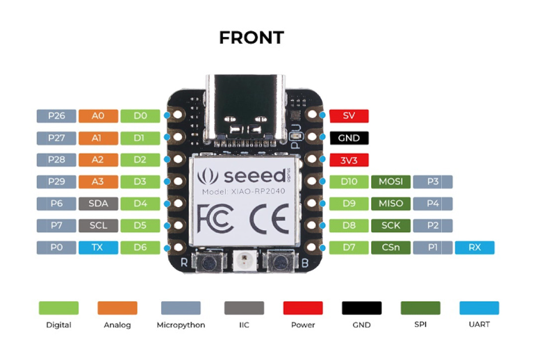
| Features | RP2040 |
|---|---|
| CPU | Dual-core ARM Cortex-M0+ |
| Clock speed | Up to 133 MHz |
| Bit depth | 32-bit |
| Storage | 264KB of SRAM, and 2MB of on-board Flash memory |
| I/O pins | 30 GPIO pins |
| Power | 1.8V - 5.5V |
| Dimensions | 20x17.5x3.5 mm |
| Bluetooth | No |
| WiFi | No |
| How to program | USB mass-storage boot mode, drag-and-drop programming |
| Special Functions | USB 1.1 Host/Device, 8 Programmable I/O (PIO) state machines |
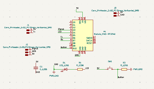
Schematic Design
PCB Design
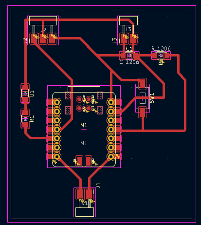
For the PCB design, I arranged all the elements so that the sensor connects directly to the corresponding pins, with some pins ready for Rx and TX communication and a button for an additional input option.
For the manufacturing of the PCB, take a look at Electronic Production Week to learn more about the steps I took.
Arduino Code
          #define led_pin D4
          #define touch_pin D3
          void setup()
          {
            Serial.begin(9600);
            pinMode(touch_pin, INPUT);
            pinMode(led_pin, OUTPUT);
          }

          void loop()
          {
            if (digitalRead(touch_pin) == HIGH)
            {
              digitalWrite(led_pin, HIGH);
              Serial.println("Touch detected!");
              delay(1000);
            }
            else
            {
              digitalWrite(led_pin, LOW);
              Serial.println("Touch not detected");
            }
            delay(1000);
          }
After uploading this code to the RP2040, the sensor successfully transmitted a signal to both the serial monitor and the LED, turning it on and off as expected.
