Machine Design
My job during this week consisted on two main roles, as a project manager and as machine designer. This both roles where crucial to get a well put together project where the main goal was to develop from scratch a CNC machine. As a result we got DuneDremer a machine that draws through a magnet and a marble figures in the sand. This through a mechanism that works through a Cartesian coordinate system based on the x and y axes. Get to know DuneDremer
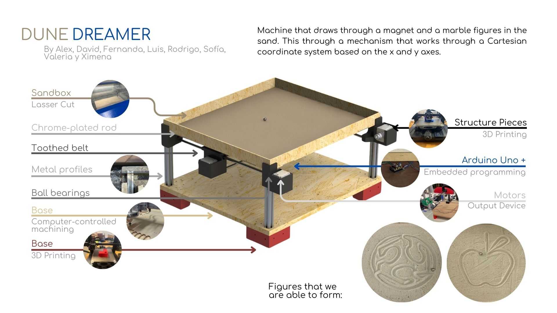
To create our machine we decided to use a cartesian mechanism where the system would be only used in a planar dimension (XY) and would have a two step motor for the Y axis and a Single motor for the X axis. To create the design we research for different commercially available machines that already use this style of kinematics like the **UltiMaker 3D printer** where the printing head moves along the XY axis.
To create our system we would three pieces that will carry the stepper motors, two of them set on two corners that will drive the Y axis (so this pieces will need to be parallel and mirrored one from another) and another piece that will be placed on the steel-rod and move along the Y axis but control the X axis.
CAD Design
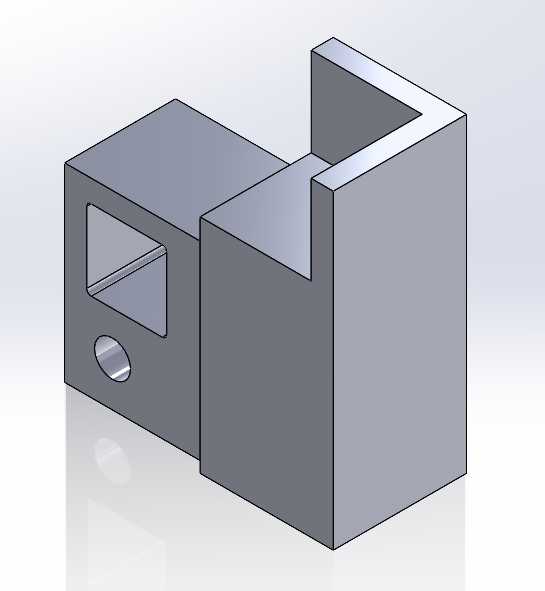
For this, the mirrored corner motor support will have a pocket to have a Nema-17 stepper motor and be fixed to the aluminum extrusion as well as having a insertion place for the Y-axis rod.For this, the mirrored corner motor support will have a pocket to have a Nema-17 stepper motor and be fixed to the aluminum extrusion as well as having a insertion place for the Y-axis rod.
At the opposite corner, we need a corner to fix a belt pulley where the belt will return to the stepper motor and an insertion place for the Y-axis rod as well.
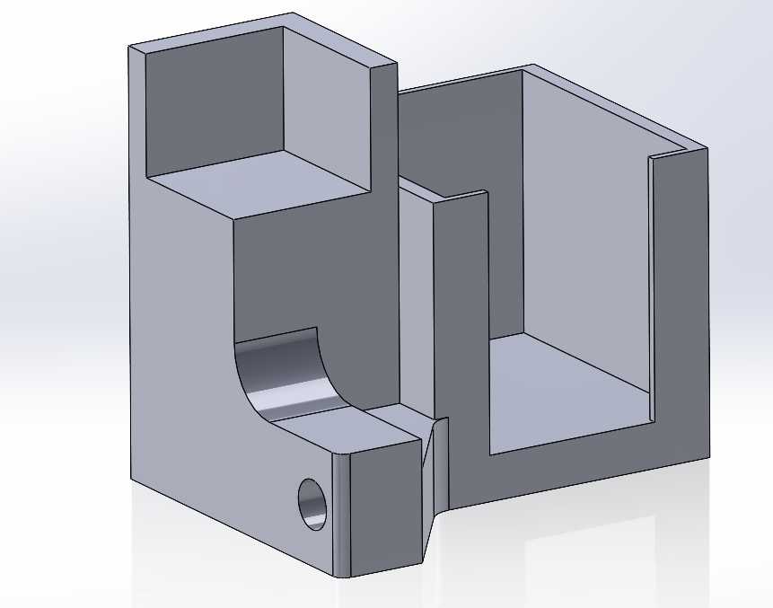
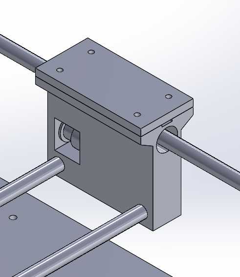
Another critical part of the mechanism is the X-axis system where another Nema motor is needed. How ever, this motor will be moving along the Y-axis, therefore the motor needs to be mounted on the rod with a linear ball bearing and have the space for a Nema 17, two rods for the X-axis and a space to lock and create tension for the dented belt.
On the opposite side, there will be another part where those two rods will be inserted, another essential criteria is to have the belt pulley as well as the linear ball bearing mechanism.
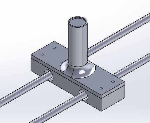
For our magnet we had a part segment where the belt is fixed to add tension to the mechanism, two sets of lineal ball bearing and a shaft to get the magnet on the proper height to be able to drive the ball on the sand.
Design criteria
As these parts will be 3D printed, there were multiple sets of rules that were taken into account:
- No greater than a 60° slope.
- Add rounding to corners where stress could be concentrated.
- No bridges greater than 20 mm.
- No walls with less than 1.6 mm thickness.
- Design all parts to be support free.
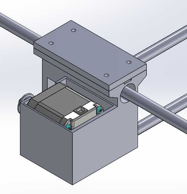
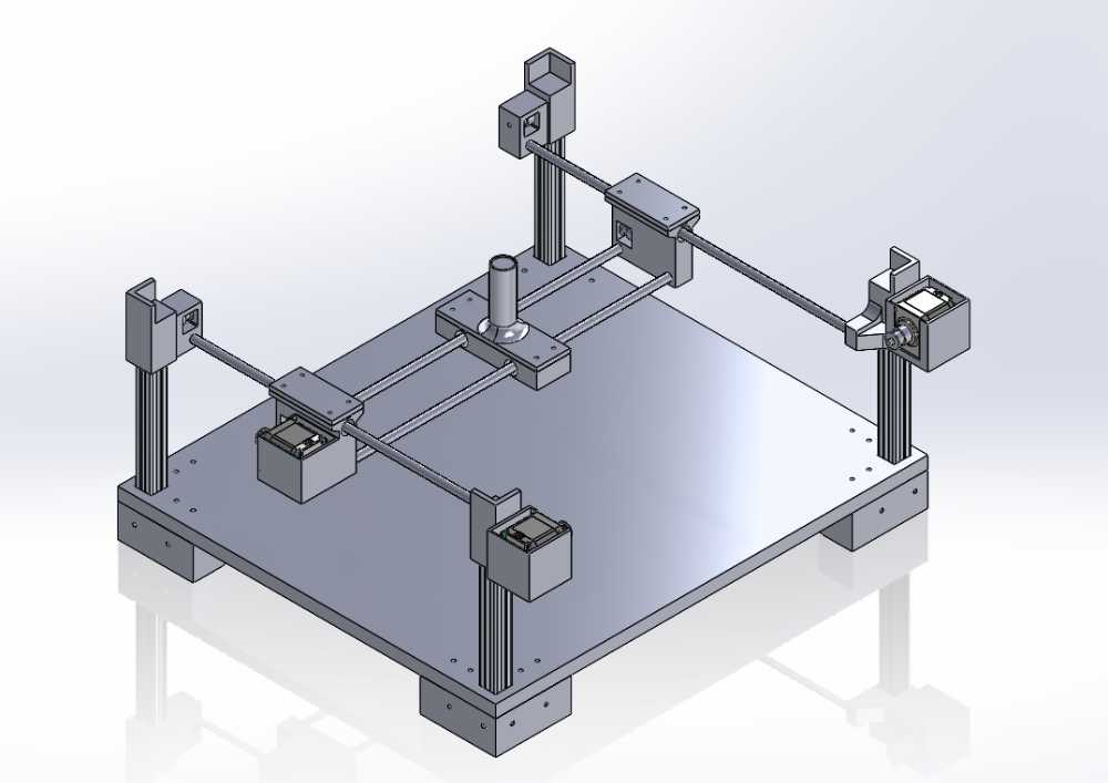
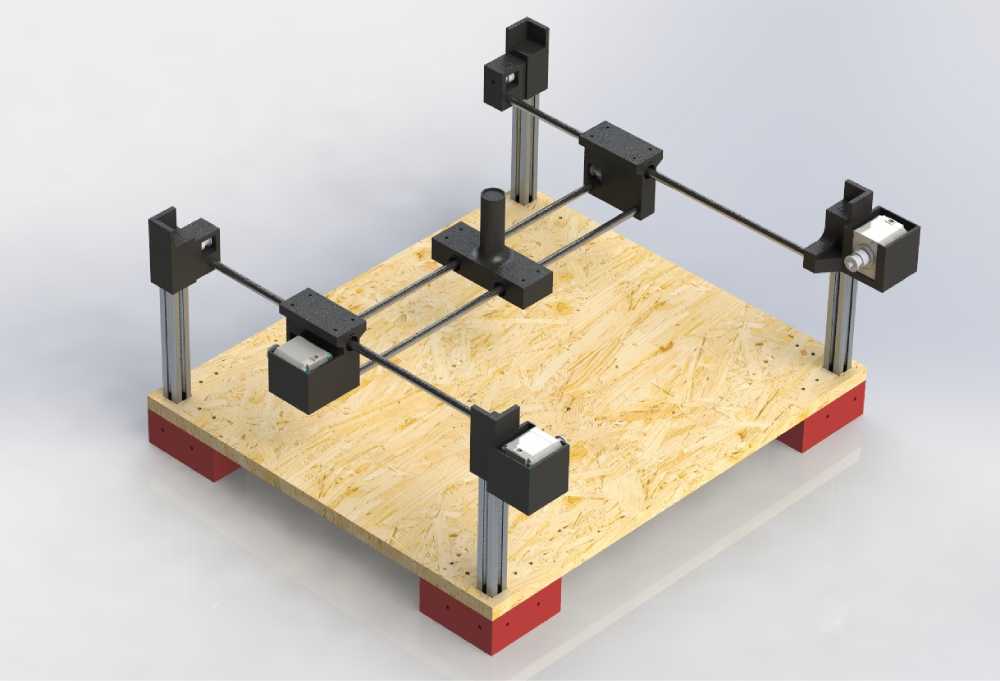
Assembly
The CNC had the assembly made to make sure that all parts are well aligned. This will be a critical to ensure that at the moment to have the physical assembly all parts will fit and the mechanism will work.
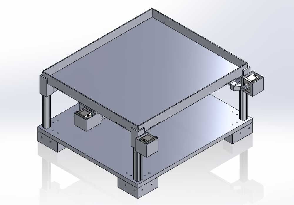
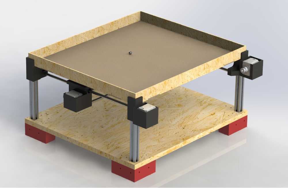
Render
This is a virtual render of our project selecting materials
Project Managment
Project management is vital in any project as it ensures that everything is organized and progresses smoothly. It involves planning, scheduling, and allocating resources effectively, ensuring that all team members understand their roles, and monitoring the project to ensure it is on track. It can help to avoid delays, cost overruns, and other potential issues that could derail the project. In the case of our CNC machine project, effective project management was crucial in coordinating the team's efforts, ensuring the efficient use of resources, and ultimately delivering a successful project.
Therefore I made sure to assign different assignments to every team member based on their background and abilities to ensure they could perform at their best. As well I was in charge of keeping tabs on everyone’s work to ensure a proper time management and workflow.
