Week8. Electronics Design
Assignments
- Group assignment:
- Use the test equipment in your lab to observe the operation of a microcontroller circuit board
- Send a PCB out to a board house
- Individual assignment:
- Use an EDA tool to design a development board to interact and communicate with an embedded microcontroller, produce it, and test it
- Extra credit: try another design workflow.
- Extra credit: design a case for it.
- Extra credit: simulate its operation.
Hero Shot
Group Assignment
Oscilloscope
An oscilloscope is an electronic measuring instrument used to observe and measure the waveform of electrical signals. It can display images of the signal over time, enabling engineers and technicians to analyze the characteristics and behavior of the signal. Oscilloscopes are widely used in electronic engineering, communications, physics, computer science and other fields.
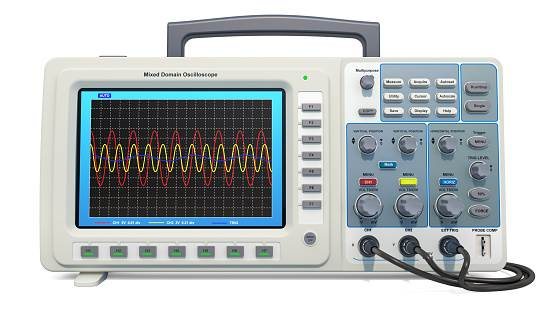
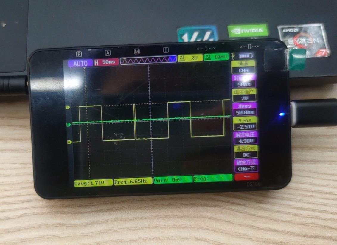
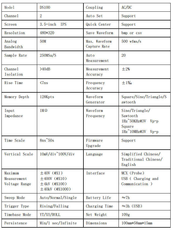
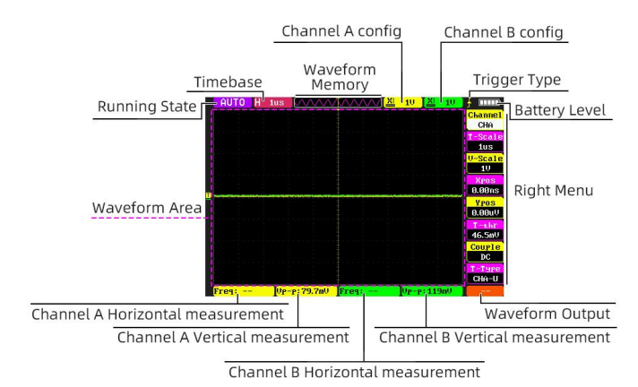
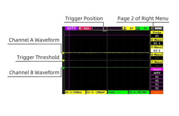
I use a handheld mini oscilloscope developed and designed by a Chinese company(正原电子)-- The DS100 operates on the same principle as other oscilloscopes. The oscilloscope's probe collects the signal to the analog front-end circuit, which amplifies and filters the signal, and then converts the signal to a digital signal. Digital signals are stored in memory and converted to analog signals by a display driver to display waveforms on the display screen. Engineers can analyze signal characteristics, diagnose circuit faults and debug circuit functions through waveforms.
Features
Main UI
Observe a Microcontroller Circuit Board
Send a PCB out to a board house
Here in Shenzhen, China, Jialichuang(嘉立创) is a very convenient company for customizing personal PCBs. Anyone can use the Jialichuang EDA software for free to design their own PCBs and place orders directly within the software. It includes a very rich component library, allowing for direct surface mount assembly according to design requirements, making the PCB ready for immediate use at a very low cost.
To understand the entire process of using Jialichuang EDA software to order and customize personal PCBs, I contacted a former colleague and sought his advice on using the EDA software. With his consent and permission, I used an open-source Arduino control board he provided to test the entire process.
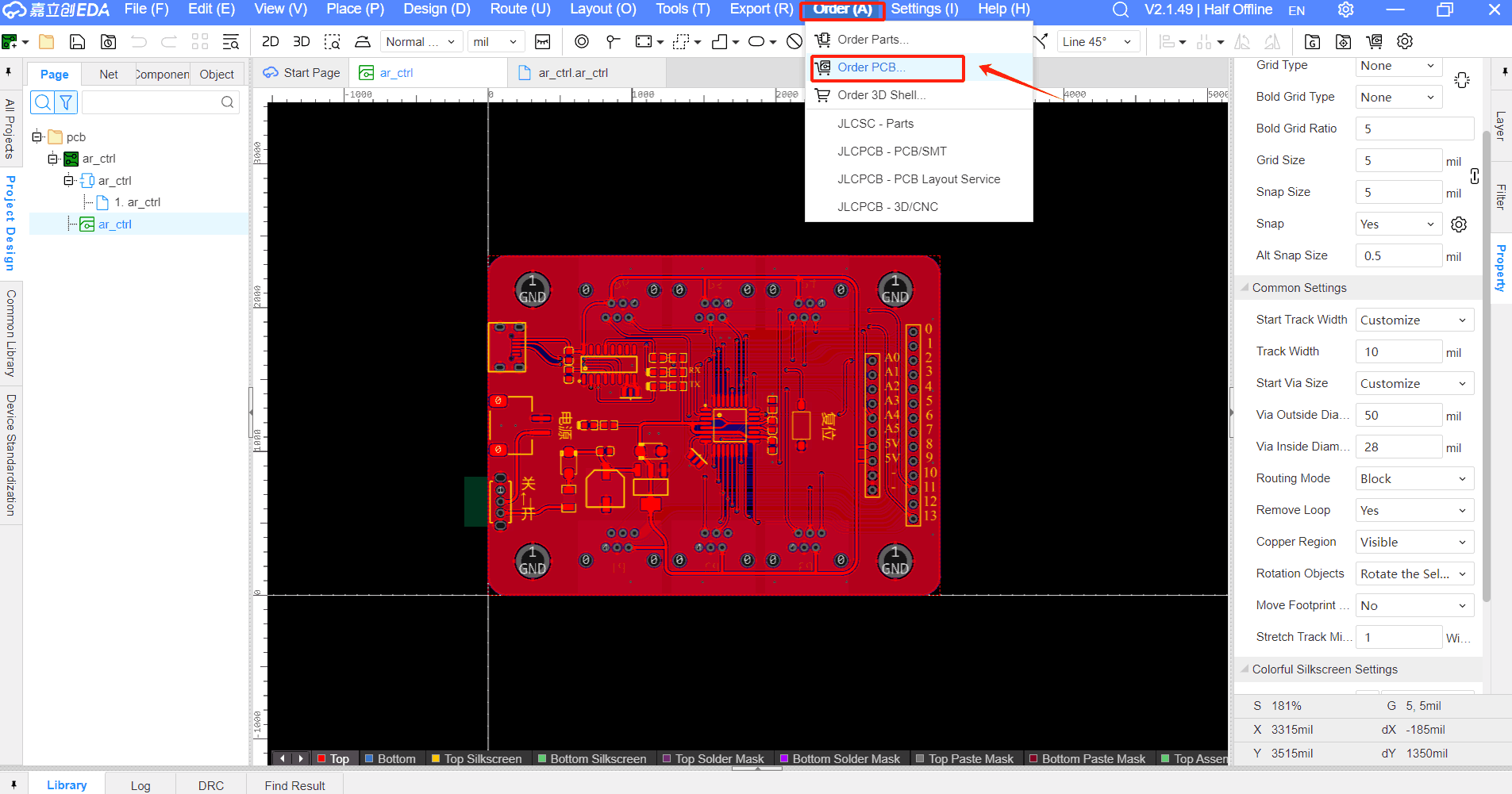
Open the PCB design file using EDA software.Select Menu bar-> Order-> Order PCB, jump to Jialichuang(嘉立创) Order Assistant page.
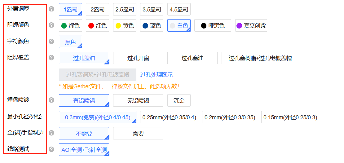
First, set the basic information, including the number of plates, layers, plate types and other information, and then select the PCB manufacturing process, including copper plating area, thickness, color, character color, pad coverage, etc., and then personalized service settings, add the consignee and pay after completion, you can wait for the PCB manufacturing to be completed.


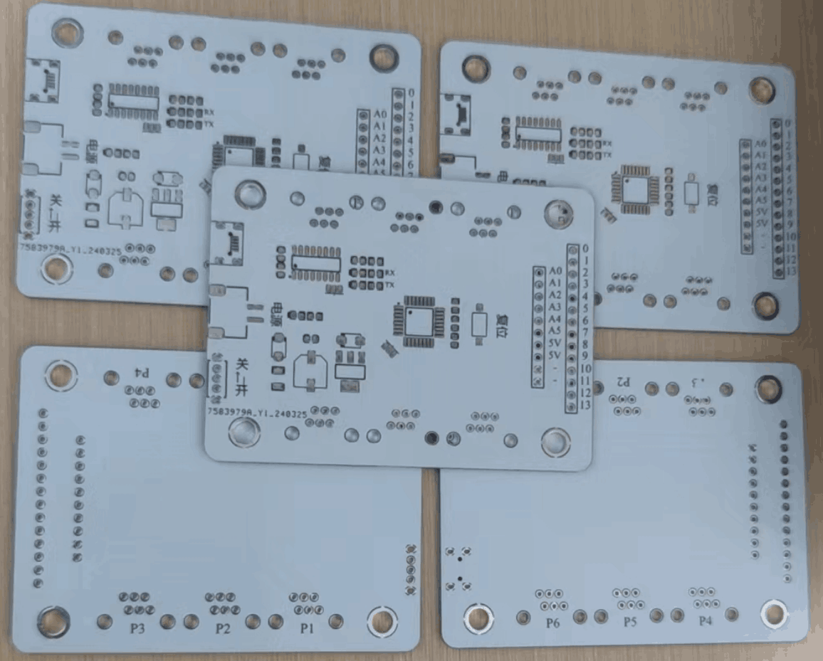
Finally, after three days of waiting, the PCB I ordered and customized has been completed according to my specifications. I chose the PCB color to be white and added solder pads, making it convenient for me to purchase the corresponding components and solder them myself. Of course, for convenience, you can also choose to have Jialichuang solder the components directly.
Individual Assignments
Design
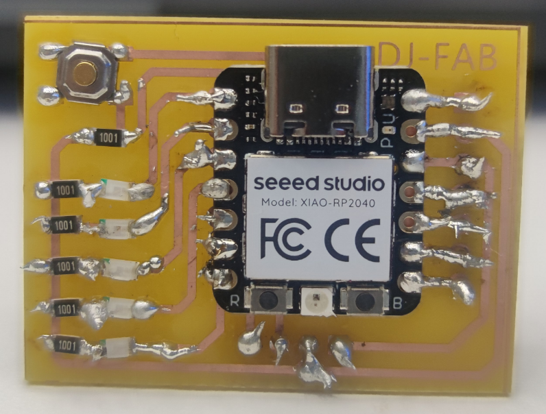
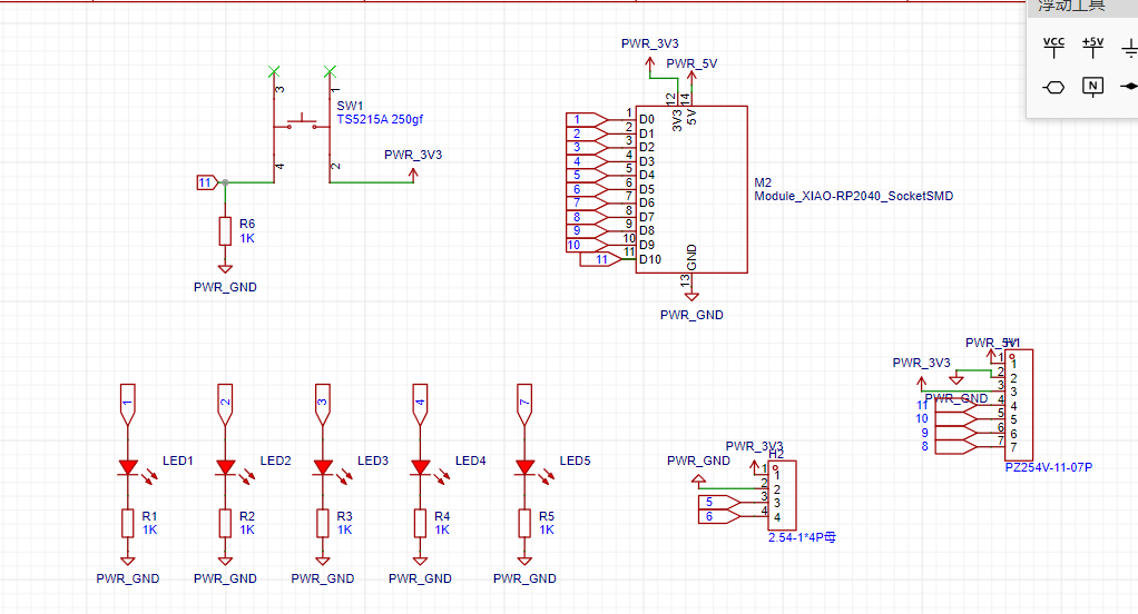
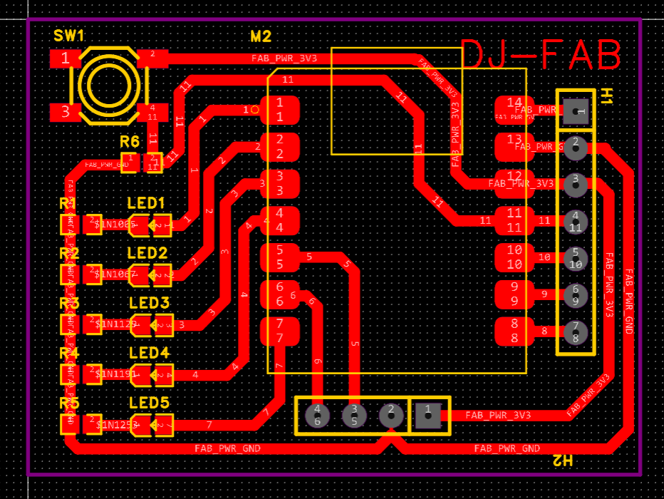
To complete the design of my board, I used Jialichuang EDA for design, and studied Jialichaung official tutorials before starting the design, which helped me to use the software faster and more skillfully.When designing a PCB, the first step is to identify the required components and then connect them in the PCB schematic. In this design, since I needed to use the XIAO Seeed RP2040 controller, I referred to its packaging method from previous lessons and attempted to add components such as resistors, SMD LEDs, buttons, and 4-pin headers. After completing the schematic design, I transferred it to the PCB layout page, arranged all the components, and connected the wires. Once all the work is done, you can test the design for any defects using the DRC check.
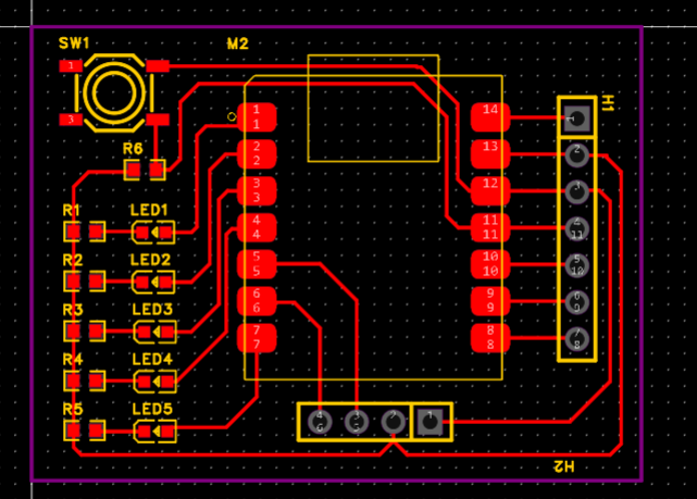
In fact, for a qualified PCB, there are a few additional considerations to keep in mind:
- The width of the connecting traces needs to be set differently based on the type to ensure signal stability. Additionally, the trace corners should be as large as possible, preferably greater than 90°.
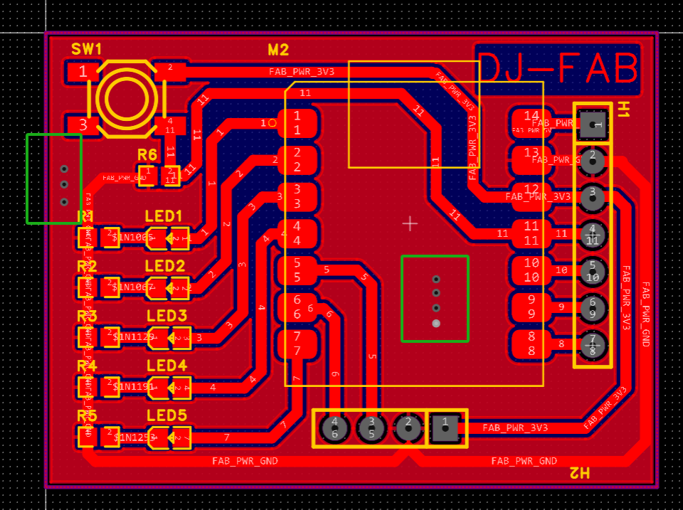
- Copper should be poured on both the top and bottom layers of the PCB.
In order to facilitate the etching of circuit wires, I have thickened and increased the area of the solder pads of the wires and components; secondly, the entire area of the PCB has been coppered, and the bottom layer and the top layer have been operated respectively. The purpose is anti-interference, and the circuit is not easily damaged; finally, a certain number of vias are prevented at the edge of the PCB board to establish electrical connections.
Drilling and soldering
1,Export the completed PCB design as PCB manufacturing files—Gerber files.
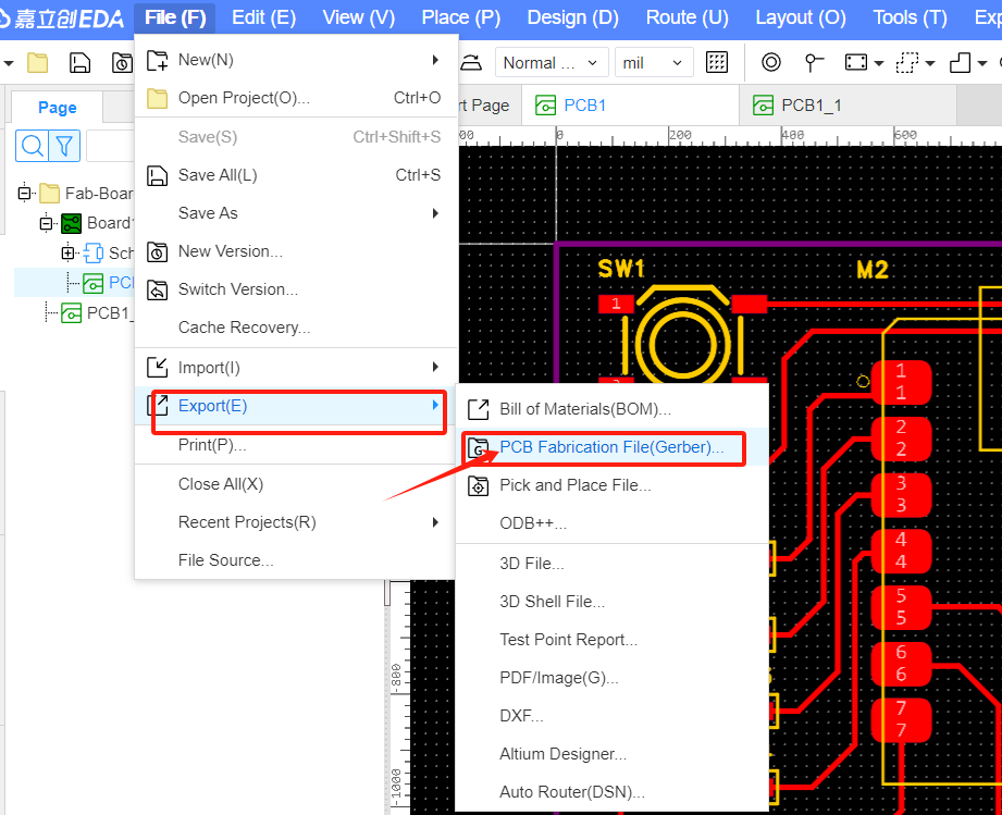
2,Use Gerber2PNG tool to generate PNG images from PCB files.here
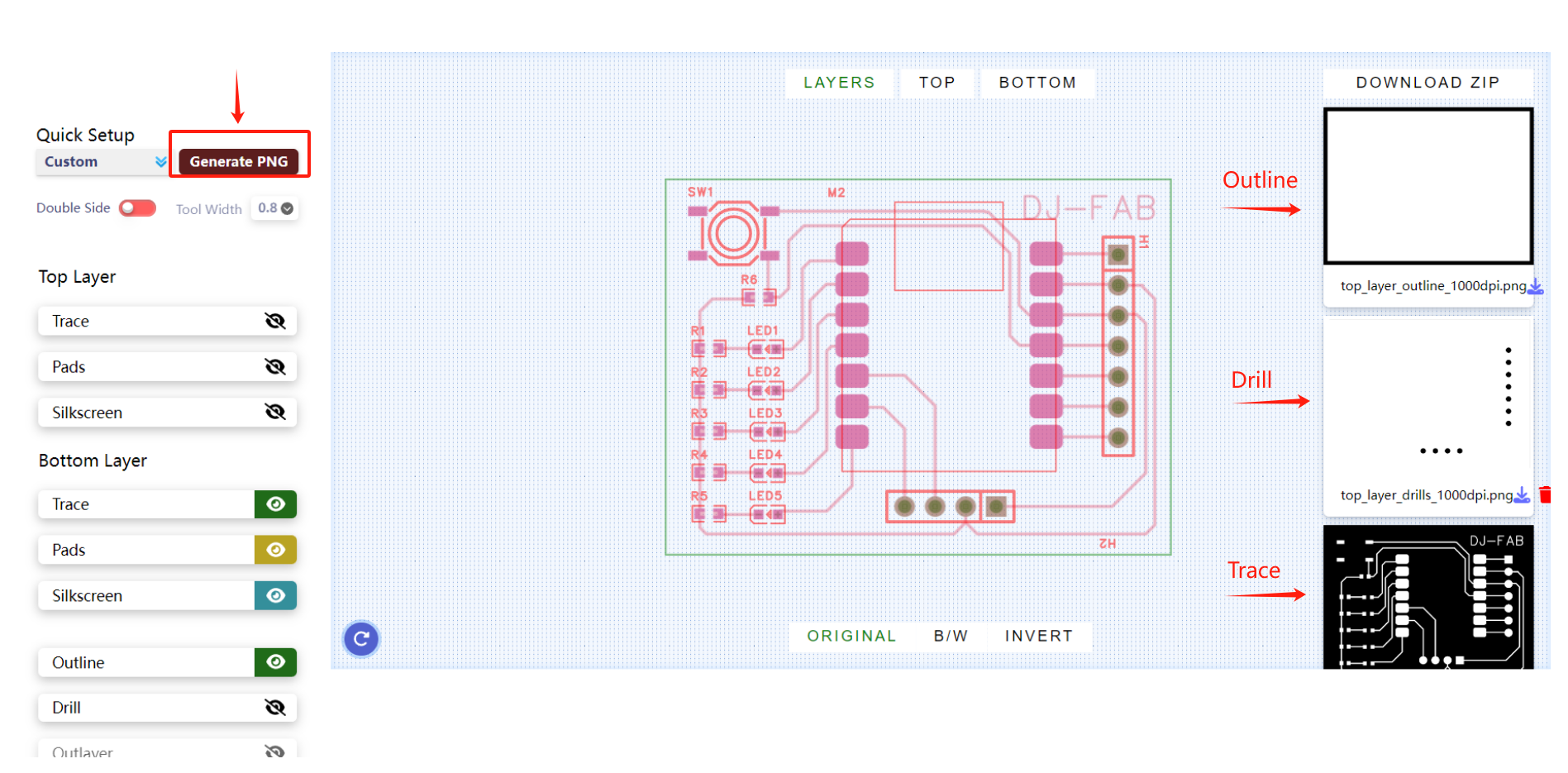
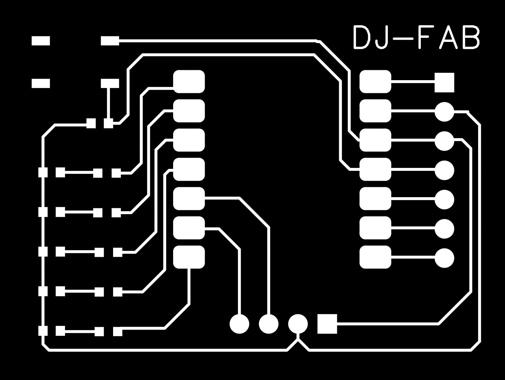
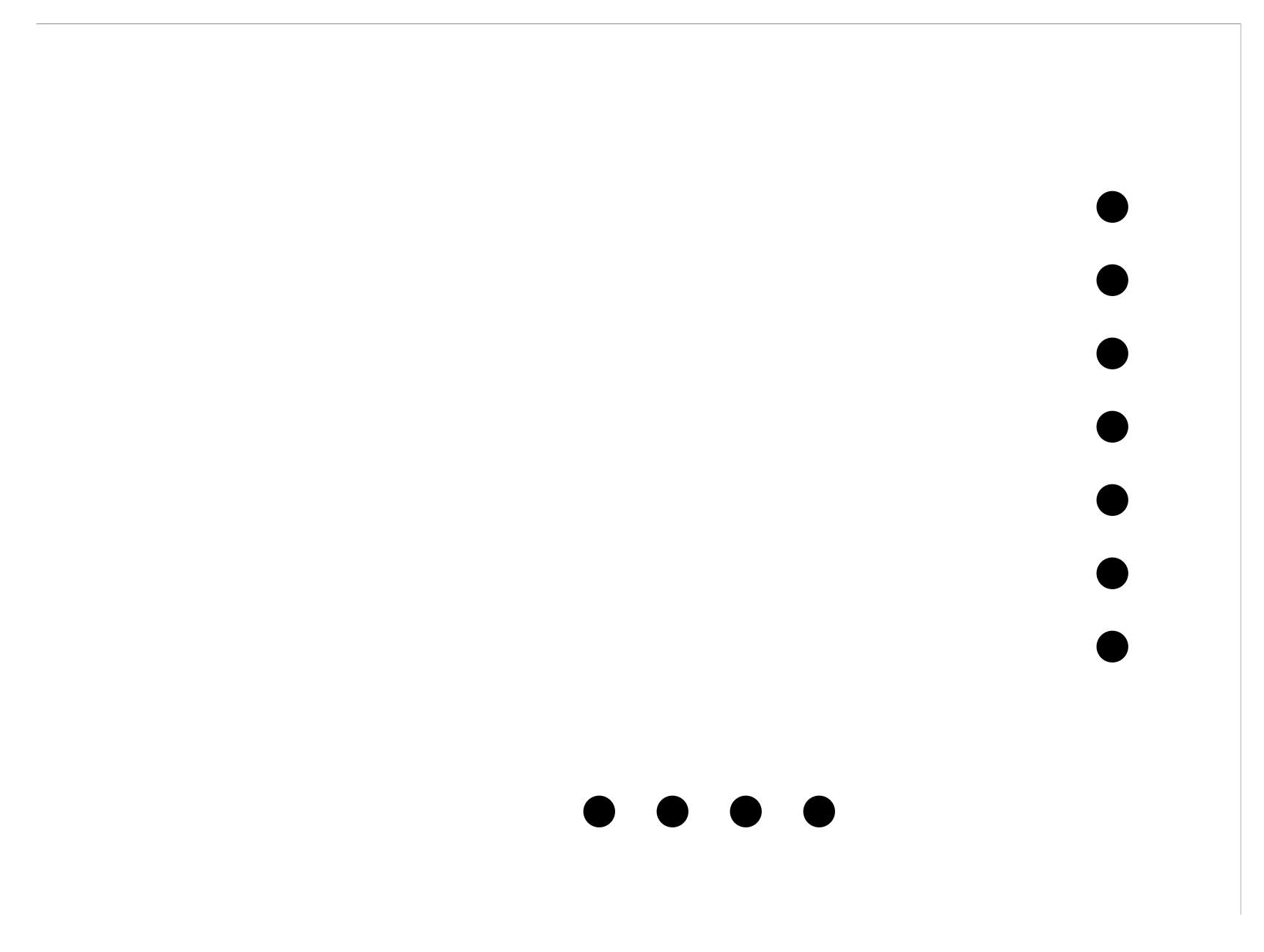

3,I used mods project to export trajectory files for CNC engraving work.
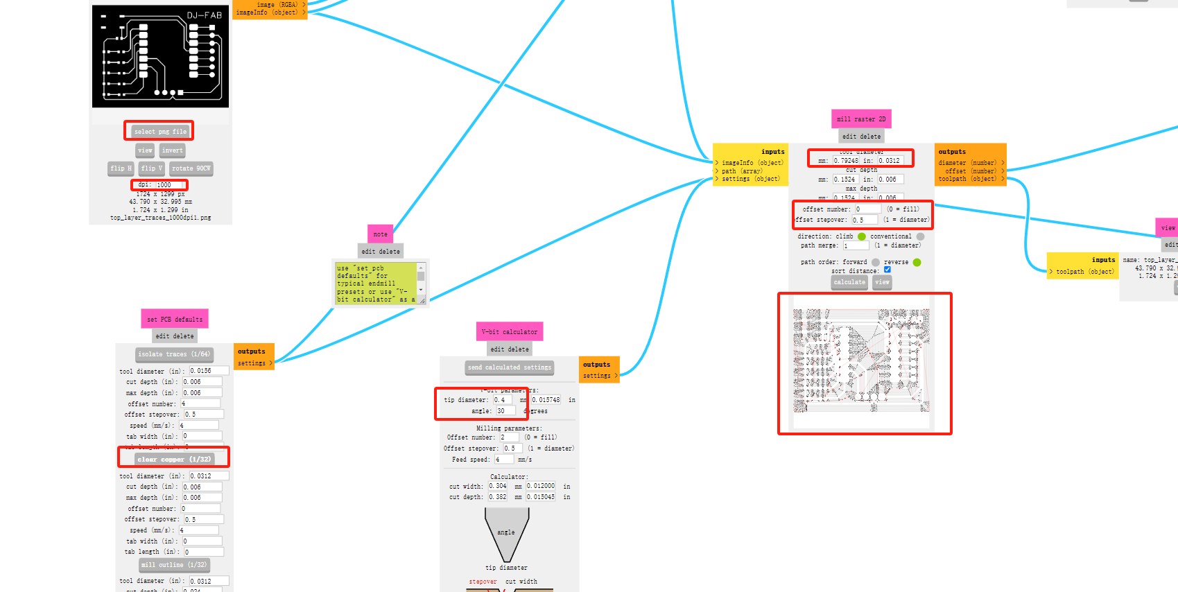
At this stage, I want to conduct more tests. Therefore, in the Traces file, I chose to mill off all copper foil except for the traces and pads. So, when I set the offset number to 15 and offset stepover to 1, the generated toolpath file is what I need.
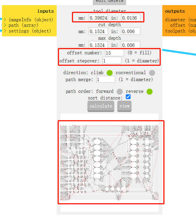
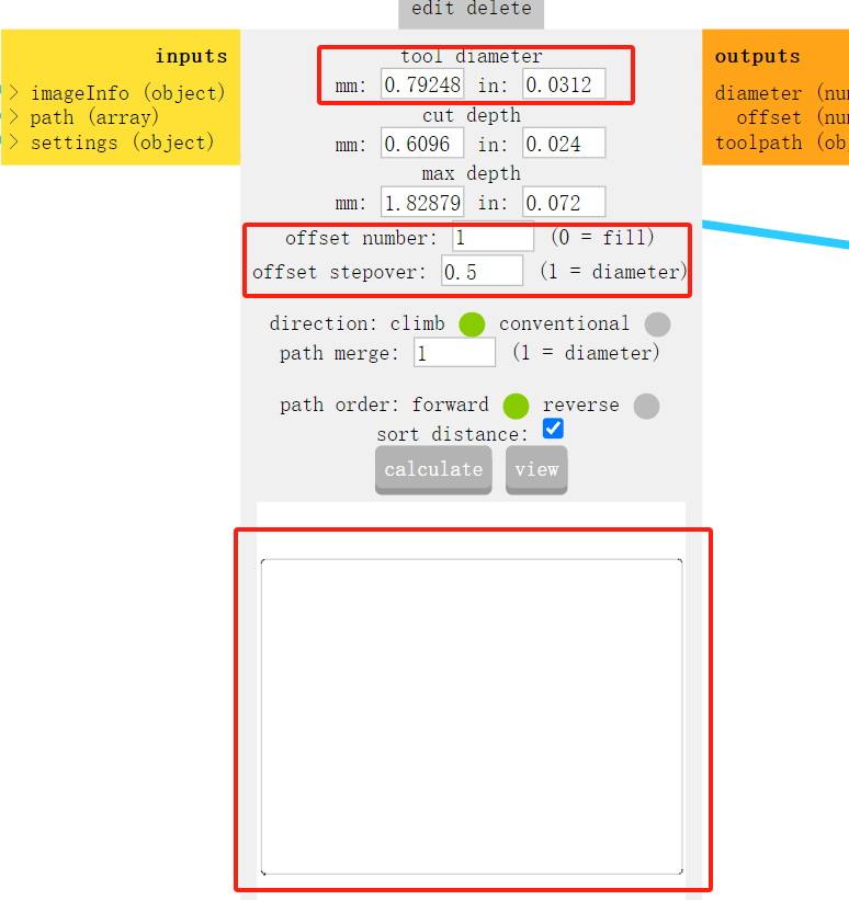
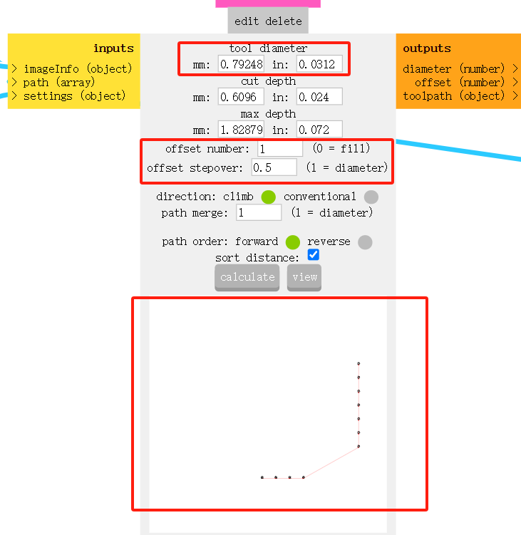
4,Since I needed to mill off all the copper foil except for the traces, this required me to use a very stable and powerful CNC machine. Therefore, with the help of my mentor, I used an excellent machine at Chaihuo Maker Space.It is made by JingYan Instruments Technology.
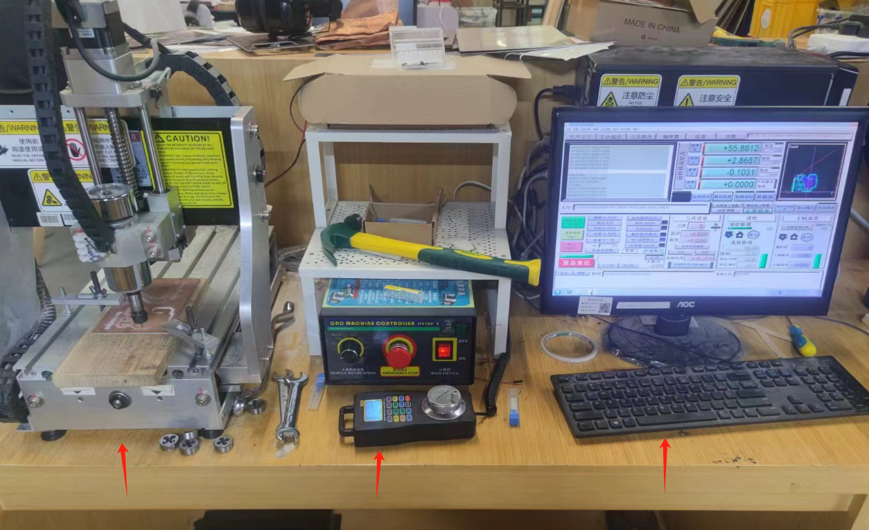
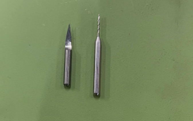
The left one is 0.4mm V-bit and right one is 0.8mm drill.Traces.png.nc is using 0.4mm V-bit.Drills.png.nc and outline.png.nc are using 0.8mm drill.
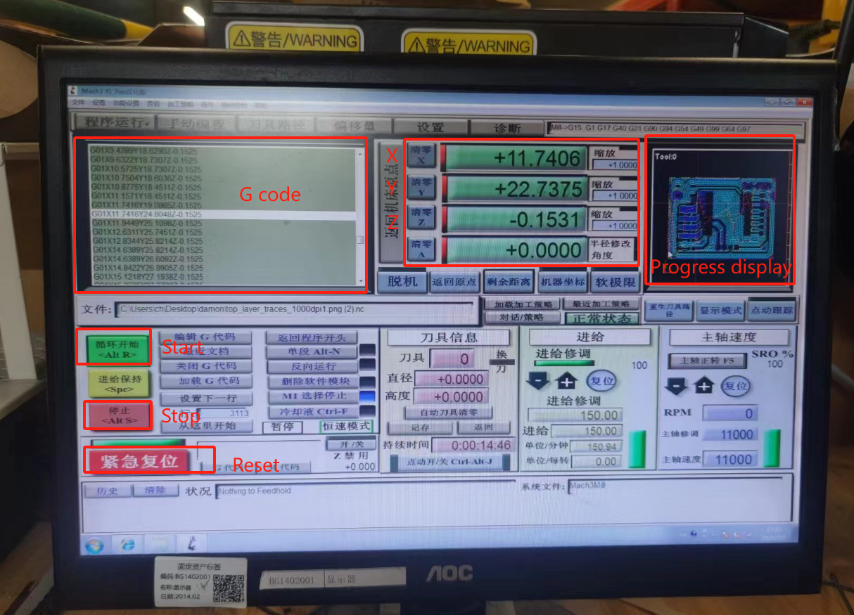
5,Load the G-code into the software, use the manual controller to move the tool head to the starting position at the origin, then zero the XYZ axes in the software. Click start, and the machine begins to run. In the software, we can observe the changes in XYZ axis data and monitor the current progress of the operation.
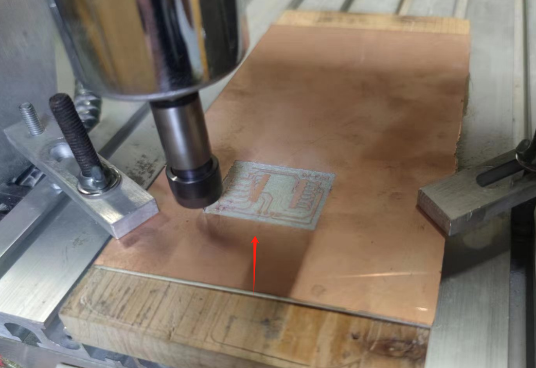
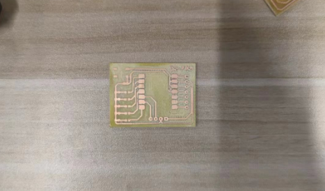
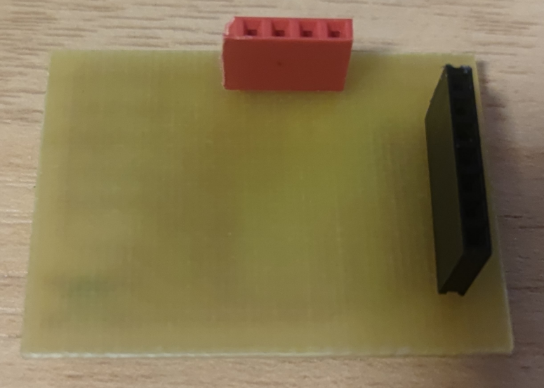
6,After milling is completed, you can use sandpaper of different grits to polish the PCB board until it reaches a smooth state.Prepare the required components in advance and weld them

Coding
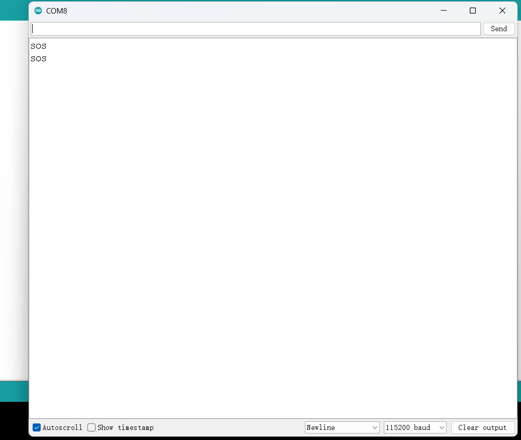
I'm going to write a morse code application for the controller, using buttons, led lights, and serial communication. First of all, I use ChatGPT to organize the idea of the function implementation, and try to write code for ChatGPT to correct and modify.For example, how are the Morse codes for the 26 letters mapped in the array?
            #include
              // Define LED pins
              const int ledPins[] = {26, 27, 28, 29, 0}; // LED Pin Array
              const int numLEDs = sizeof(ledPins) / sizeof(ledPins[0]); // LED Qty

              // Define key pins
              const int buttonPin = 3; // button pin

              // Morse code table
              const char* morseAlphabet[] = {".-", "-...", "-.-.", "-..", ".", // A-E
                                               "..-.", "--.", "....", "..", ".---", // F-J
                                               "-.-", ".-..", "--", "-.", "---", // K-O
                                               ".--.", "--.-", ".-.", "...", "-", // P-T
                                               "..-", "...-", ".--", "-..-", "-.--", "--.."}; // U-Z

              // Dots and Dashes
              const int dotDuration = 200;
              const int dashDuration = dotDuration * 3;
              const int interElementDelay = dotDuration;
              const int interCharacterDelay = dashDuration;

              void setup() {
                // Initialize LED pins
                for (int i = 0; i < numLEDs; i++) {
                  pinMode(ledPins[i], OUTPUT);
                  digitalWrite(ledPins[i], LOW); // Initial status OFF LED
                }
                pinMode(buttonPin, INPUT_PULLUP);   // Initialize key pins
                Serial.begin(9600);     //Initialize serial communication
              }
              // Send Morse code.
              void sendMorseCode(const char* morse) {
                for (int i = 0; morse[i] != '\0'; i++) {
                  if (morse[i] == '.') {
                    digitalWrite(ledPins[i], HIGH);
                    delay(dotDuration);
                    digitalWrite(ledPins[i], LOW);
                  } else if (morse[i] == '-') {
                    digitalWrite(ledPins[i], HIGH);
                    delay(dashDuration);
                    digitalWrite(ledPins[i], LOW);
                  } else if (morse[i] == ' ') {
                    delay(interElementDelay);
                  }
                }
              }
              // Detect the key and send the corresponding letter of Morse code
              void loop() {
                if (digitalRead(buttonPin) == HIGH) { // If the button is pressed
                  // Press the button to send Morse code for "SOS."
                  for (int i = 0; i < 3; i++) {
                    sendMorseCode(morseAlphabet[18]); // 'S'
                    delay(interCharacterDelay);
                    sendMorseCode(morseAlphabet[14]); // 'O'
                    delay(interCharacterDelay);
                    sendMorseCode(morseAlphabet[18]); // 'S'
                    if (i < 2) {
                      delay(interCharacterDelay);
                    }
                  }
                  Serial.println("SOS"); // Serial output "SOS"
                  delay(1000); // Delay for a period of time to avoid repeated transmissions
                }
              }
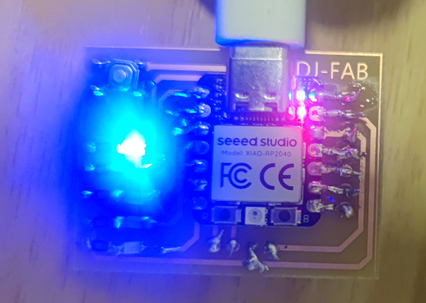
Upload the program to the control panel, check the effect
