Week7. Computer controlled machining
Assignments
- Group assignment:
- Do your lab's safety training.
- Test runout, alignment, fixturing, speeds, feeds, materials, and toolpaths for your machine
- Individual assignment:
- Make (design+mill+assemble) something big (~meter-scale)
- Extra credit: don't use fasteners or glue.
- Extra credit: include curved surfaces.
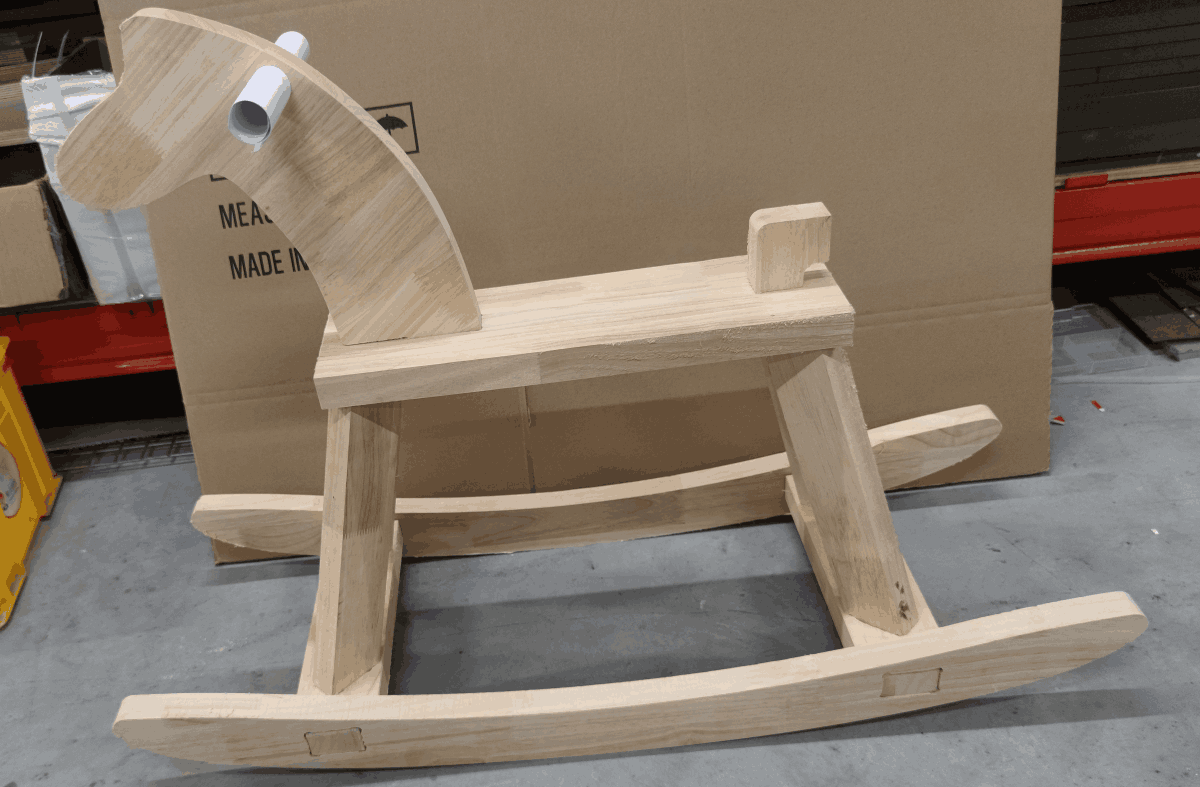
Hero Shot
Group Assignment
Safety Training
Before using it, I learned to use it safely.
Before Use
- Ensure thorough training and understanding of the operating manual before using the CNC engraving machine. Understand the machine's functions, safety features, and how to operate it correctly.
- Check the work area of the machine for cleanliness and remove any potential obstructions that could interfere with operation or pose a hazard.
- Wear appropriate personal protective equipment, such as safety glasses, earplugs, gloves, and snug-fitting clothing, to prevent injury.
During Use
- Maintain vigilance during operation and refrain from leaving the machine unattended to prevent accidents.
- Avoid operating the machine unsupervised, especially when close to rotating components or cutting tools.
- Operate with moderation and always maintain smooth, stable operation to avoid damaging the machine or causing workpiece ejection hazards.
- Refrain from touching any rotating or moving parts of the machine while it is in operation to prevent injury.
After Use
- Power off the CNC engraving machine and return all related components to their original positions, such as tools, tool holders, etc.
- Clean the machine and its surrounding area to ensure there are no debris or cutting residues left.
- Perform regular maintenance and inspection on the machine to ensure its proper operation and safety.
- Store the machine in a secure location away from children or unauthorized individuals to prevent accidental contact or operation.
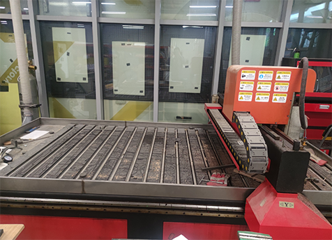
Tests
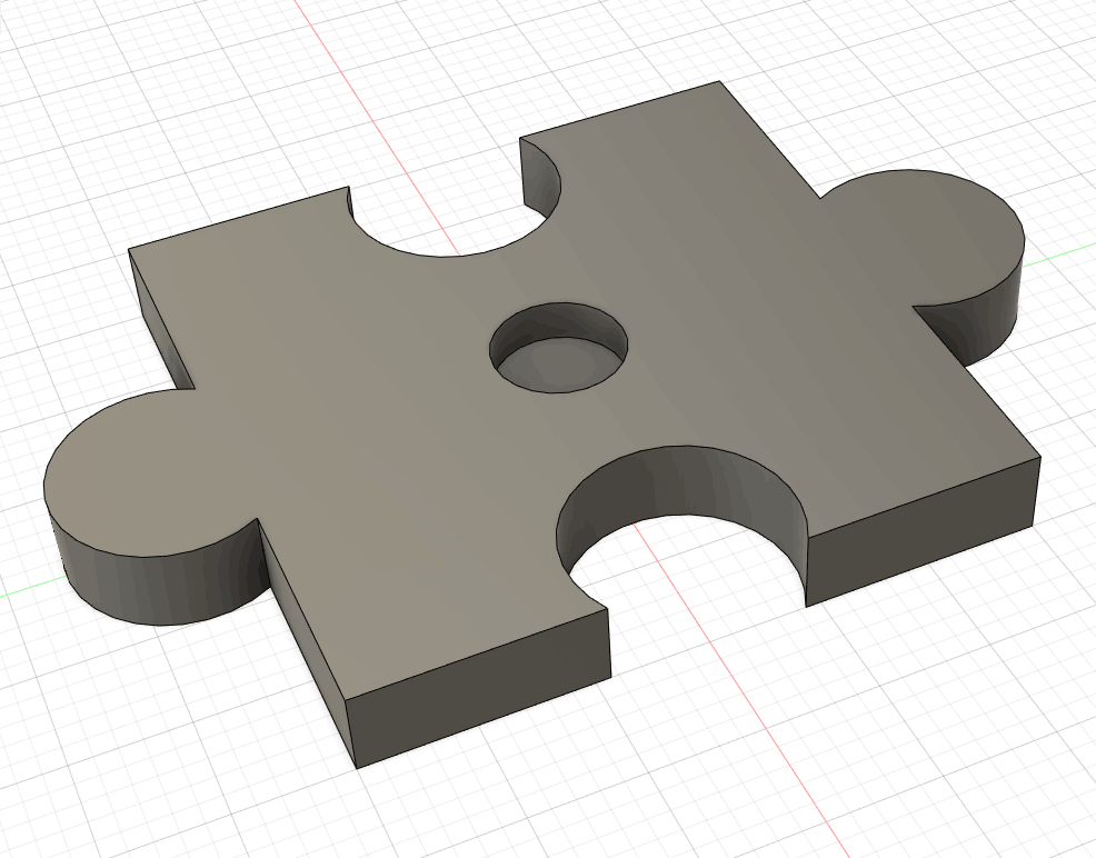
In order to test the parameters of the machine, working conditions, materials, etc., I designed a component for testing.

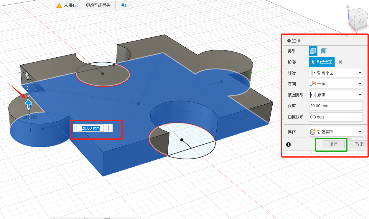
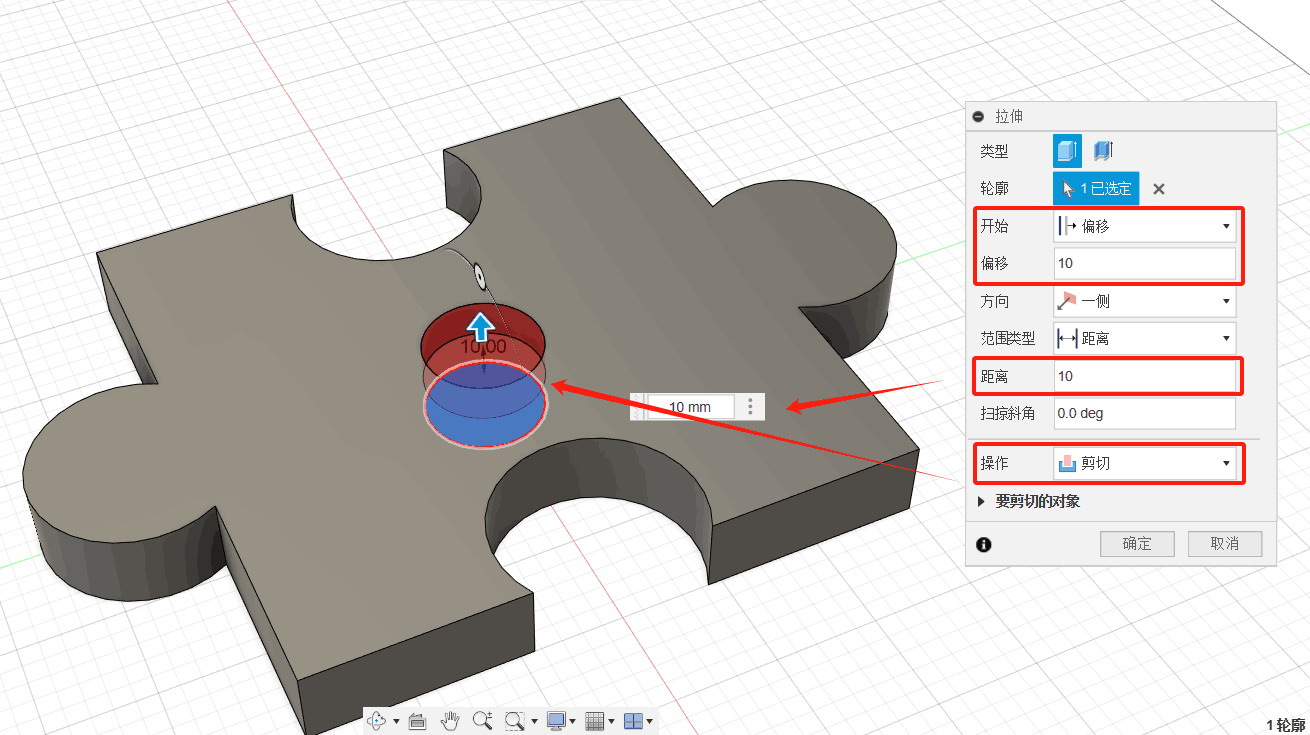
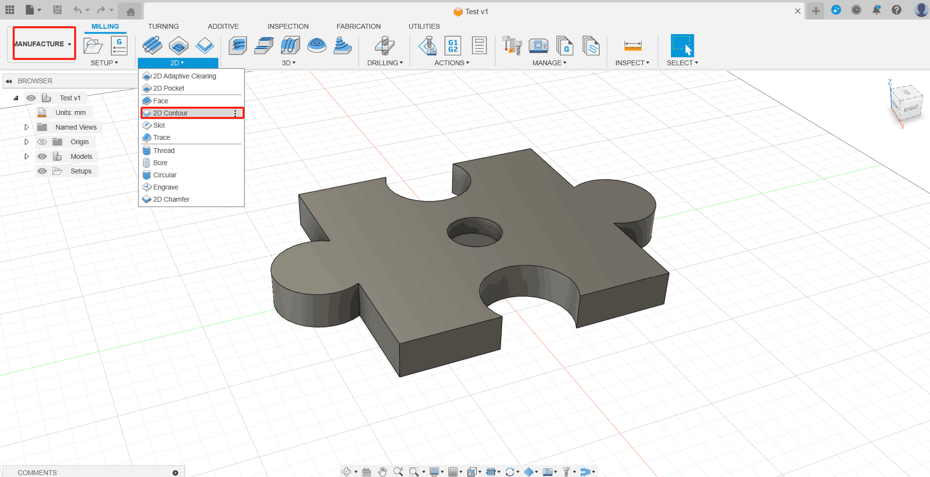
2D Contour
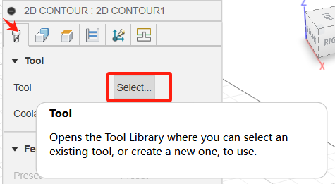
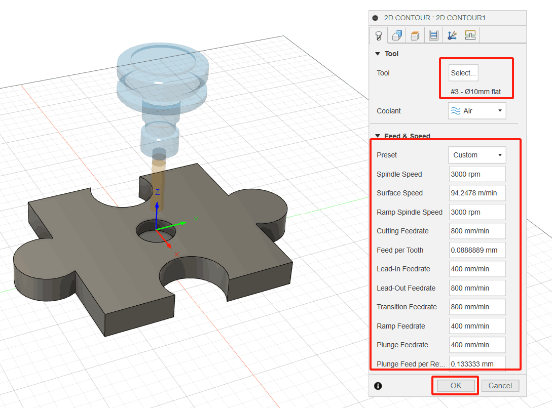
1. From the 2D Profile command palette, open the Select Tool dialog box. (1) On the Milling tab of the Manufacturing toolbar, select 2D> 2D Profile image. The 2D Profile command palette opens; (2) On the Tools tab image, click Select. This opens the tool library.
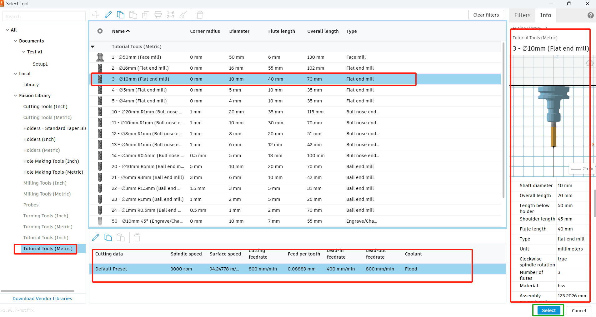
2. Open the tool library and select the appropriate props. Here, the choices are:
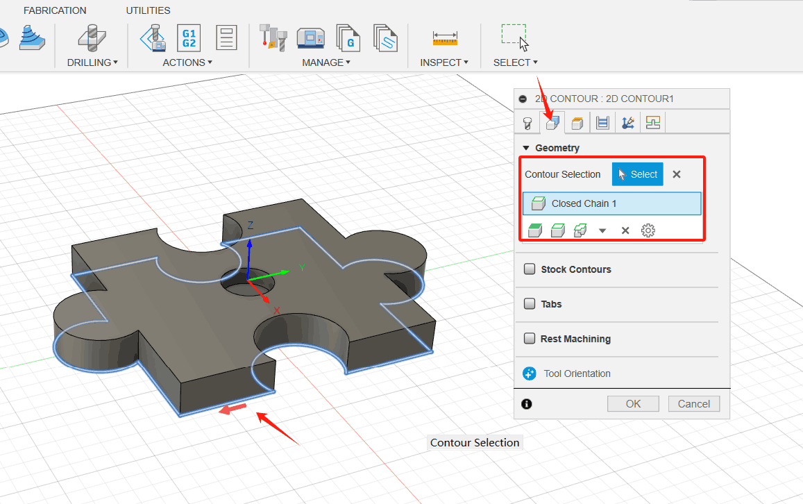
3. Select the bottom front edge as the outline of the chain selection. (1) Click the Geometry tab image; (2) Make sure the Profile Selection button is active so that you can select the outside edges of the part geometry to run the tool; (3) Move the mouse pointer above the bottom front edge; (4) When the edge is highlighted, click it. The edge is automatically selected as a chain. Notice the blue chain around the part. The red arrow should point clockwise (CW) around the part on the outside.
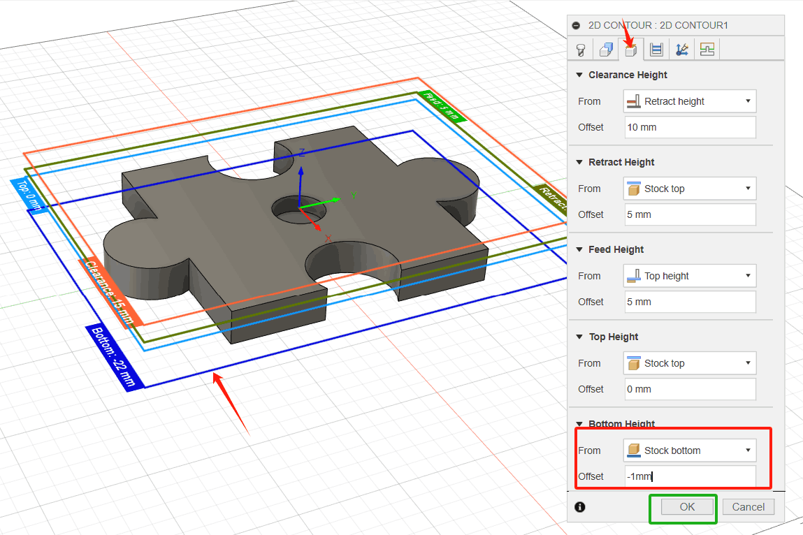
4. To ensure that the tool passes all the way through the blank, lower the bottom height by 1 mm and start the calculation. (1) Click the Height tab image. A preview of the height will be displayed. Height is color-coded and labeled for easy identification; (2) The Bottom Height drop-down menu should be set to Bottom of Model; (3) Set the bottom height offset to-1 mm. Notice that the dark blue plane Bottom Height moves downward; (4) Click OK to begin the calculation.
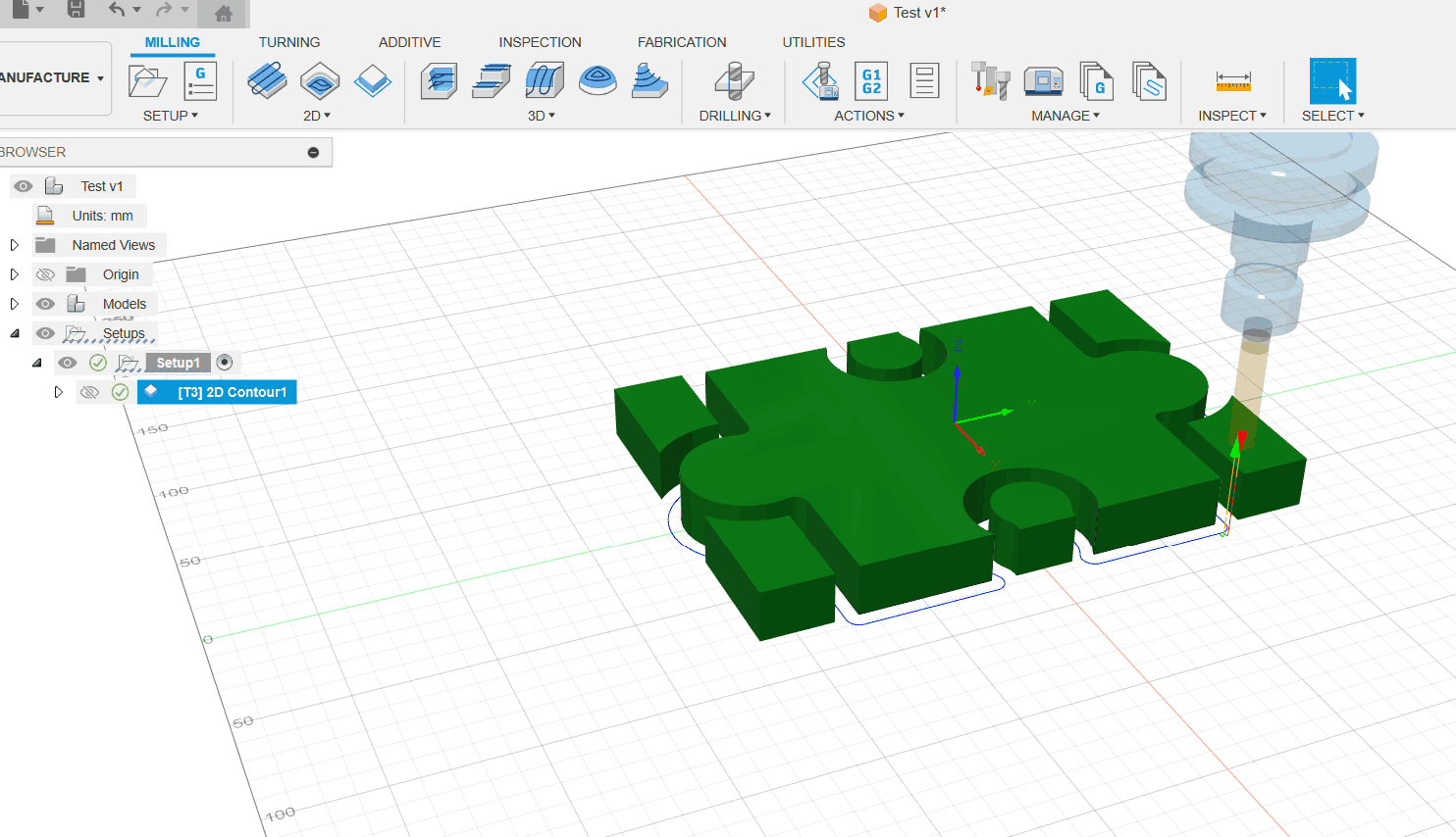
5. Click OK to complete the setup
2D Pocket
1. From the 2D Trenching command palette, select #2 -Ø8mm Flat Blade. (1) On the Milling tab of the Manufacturing toolbar, select 2D> 2D Grooves image. The 2D Trenching command palette opens; (2) Select the Tools tab.
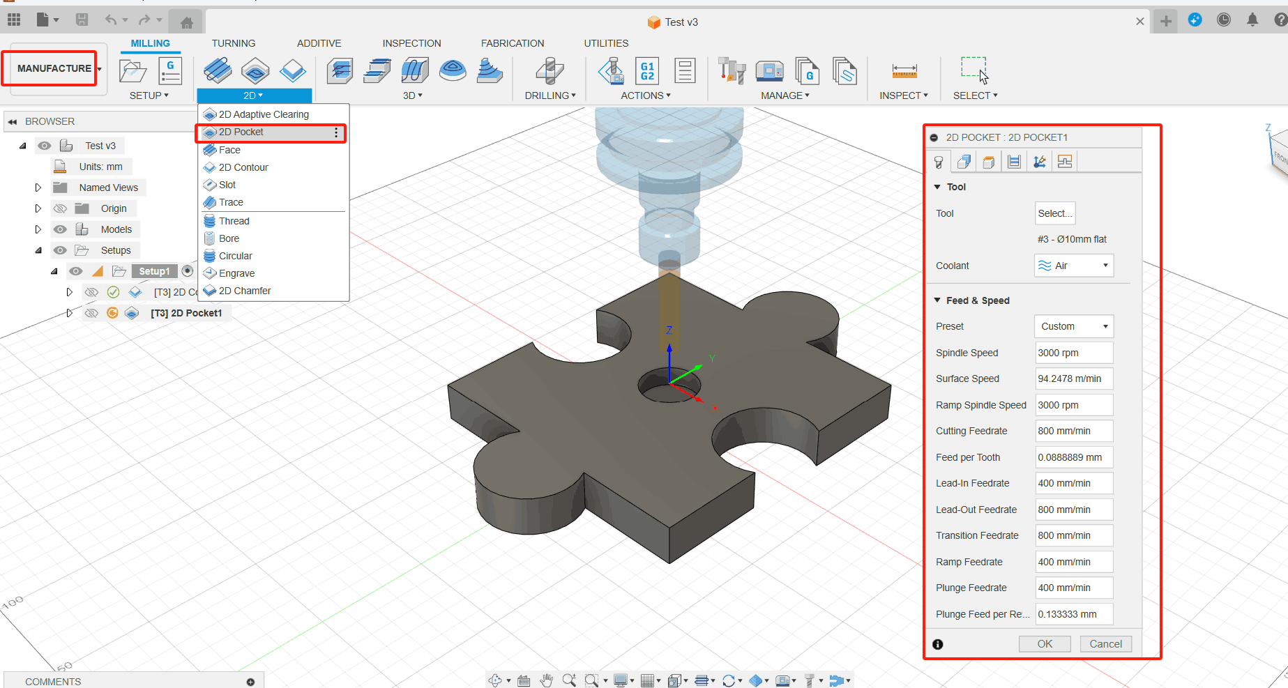
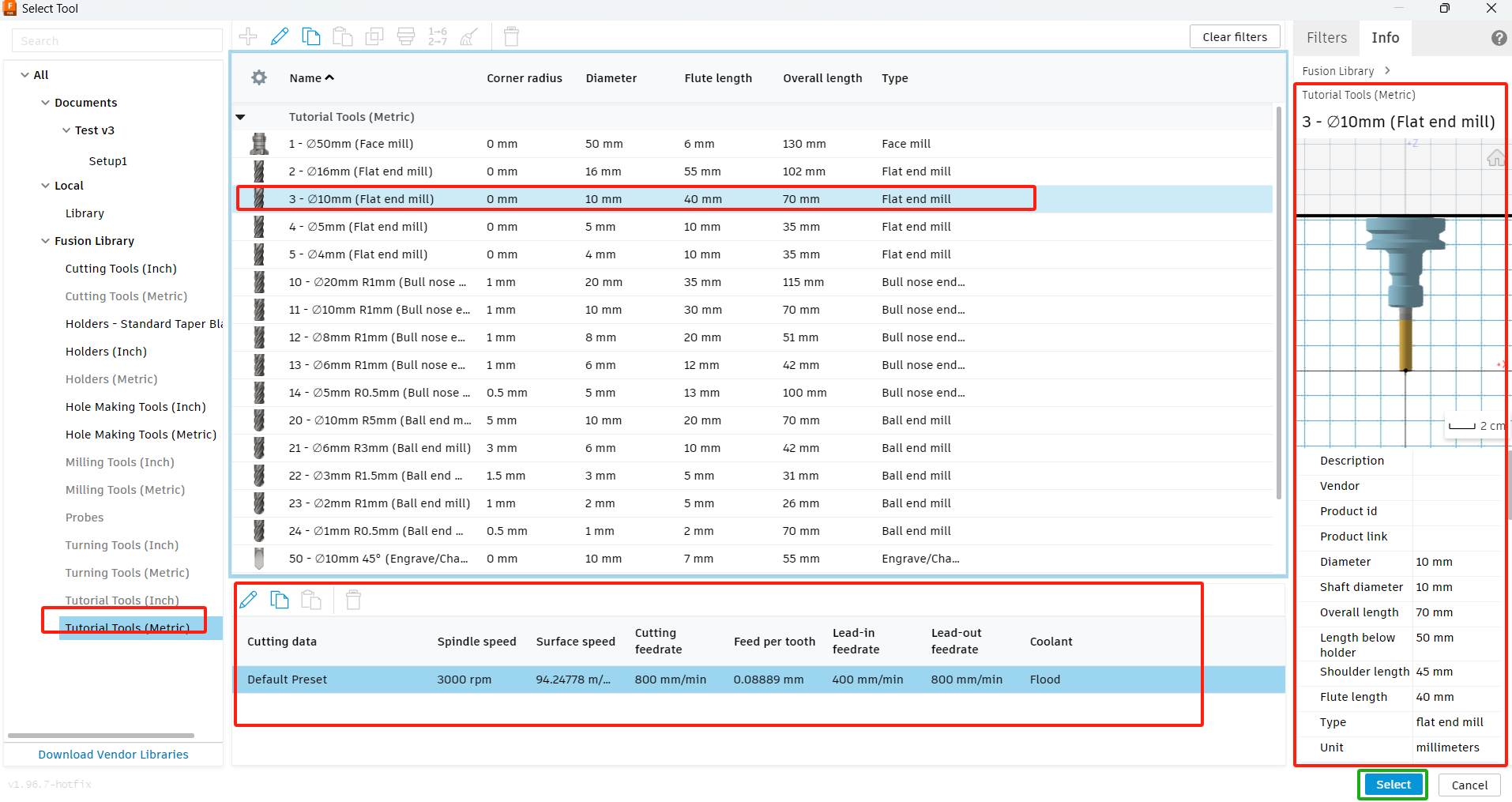
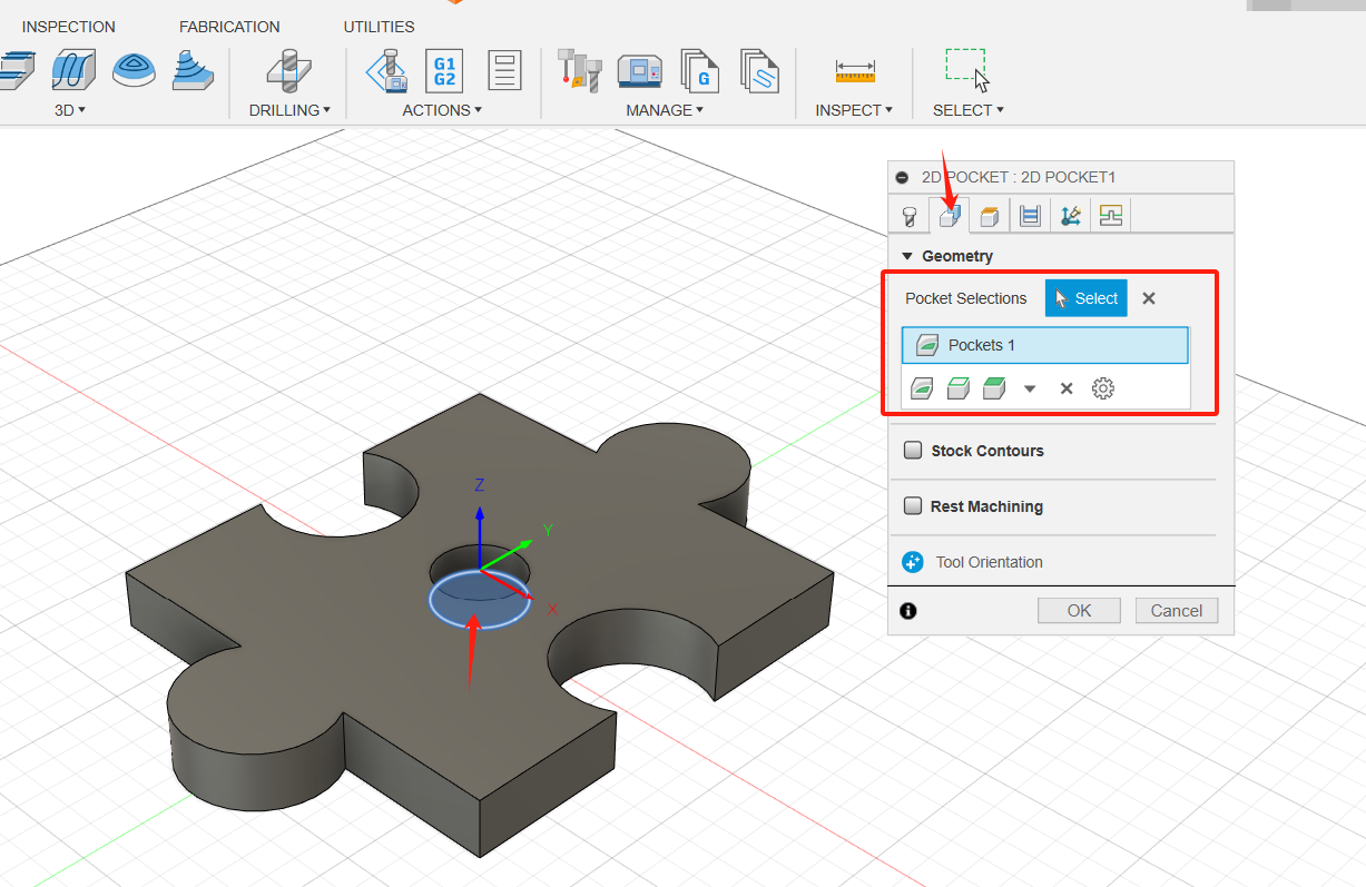
2. Select the shape of the grooving area. (1) On the 2D Trenching command palette, click the Geometry tab image; (2) Select the bottom of the trench. The face is highlighted in blue.
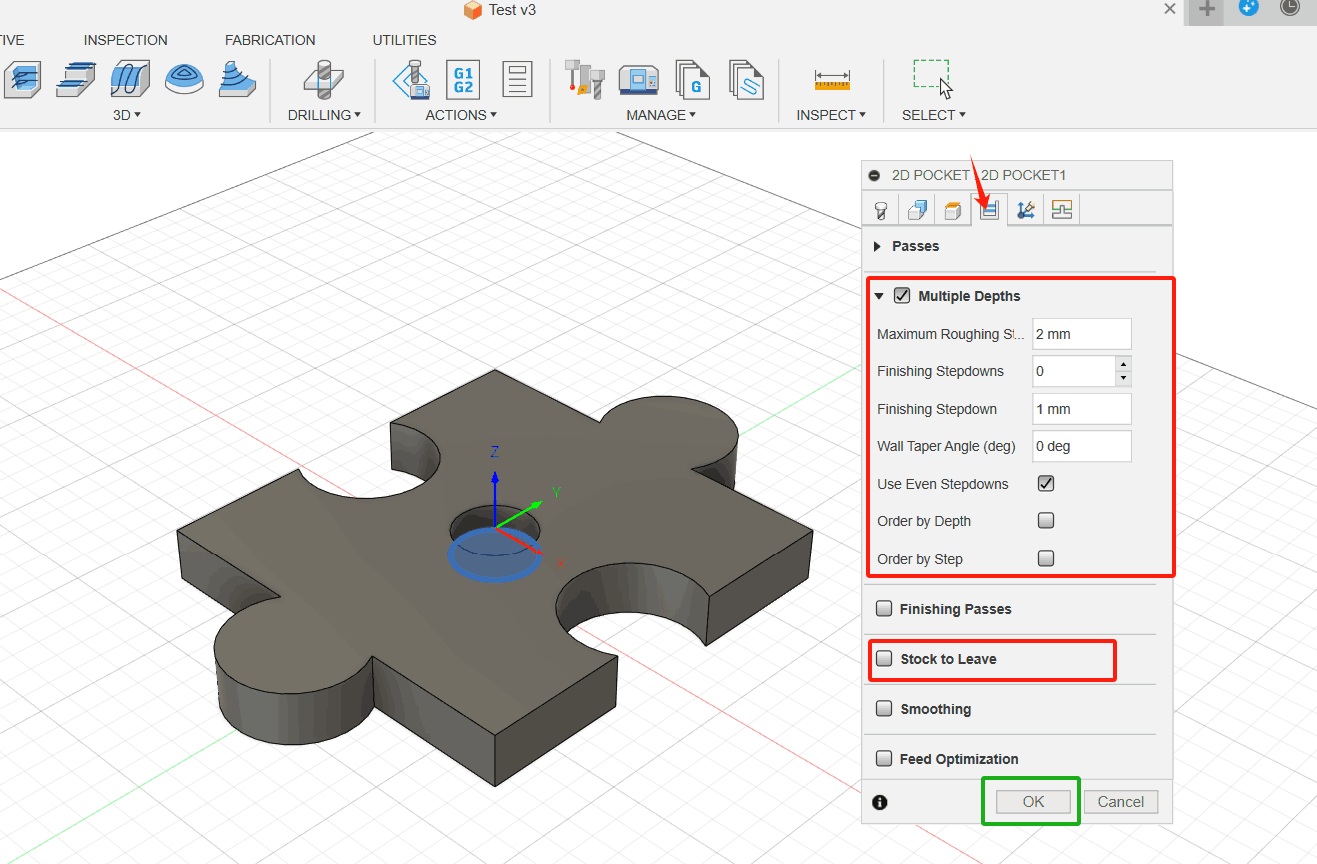
3. Create depth and finish down pitches for layered milling. Clear Machining Allowances. (1) Click the "Machining Path" tab image. This group of settings controls how the 2D grooving tool path is calculated. To clean the pocket, the tool path is generated in multiple Z layers starting at the top of the blank and moving down to the bottom of the pocket in 2 mm steps. (2) Enable the "Layered Milling Depth" check box.; (3) Set the Maximum Roughing Down Step to 2 mm; (4) Set the "finishing down step" to 1; (5) Disable the Machining Allowances check box. Since 2D Grooving is a roughing operation, blanks remain by default. In this example, we do not need additional finishing cuts; (6) Click OK to begin the calculation.
4. Click OK to complete the setup.
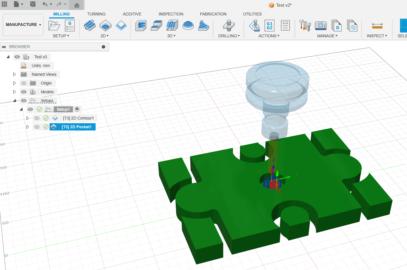
While communicating and coordinating the use of CNC machines, I started using Fusion 360 to design models and tried to learn CNC machining methods using the software’s built-in features. This included setting the tool size, speed, and machining methods, as well as using animation to simulate the machining process. This approach gave me a first impression of CNC machining and helped me build a concept for actual CNC machine usage. However, during my actual operation, due to equipment usage limitations—such as not being able to use my own computer and having to reprocess the machining files according to the CNC machine model—the group and individual assignments could not be compared. Nevertheless, operating the software for group assignments helped establish the concept and process of CNC machining, which has been beneficial for me personally.
Individual Assignments
During homework this week, I had the big moment of my life when my baby was born. So I decided to make one wooden horse for my kid.
Attention
Safety is the most important issue. Even though I have learned about operating CNC machines safely, I still cannot guarantee complete safety as this is my first time using one. To ensure safety, I invited the equipment manager to assist and guide me, preventing any dangerous situations. I am very grateful for the manager's help.
Design
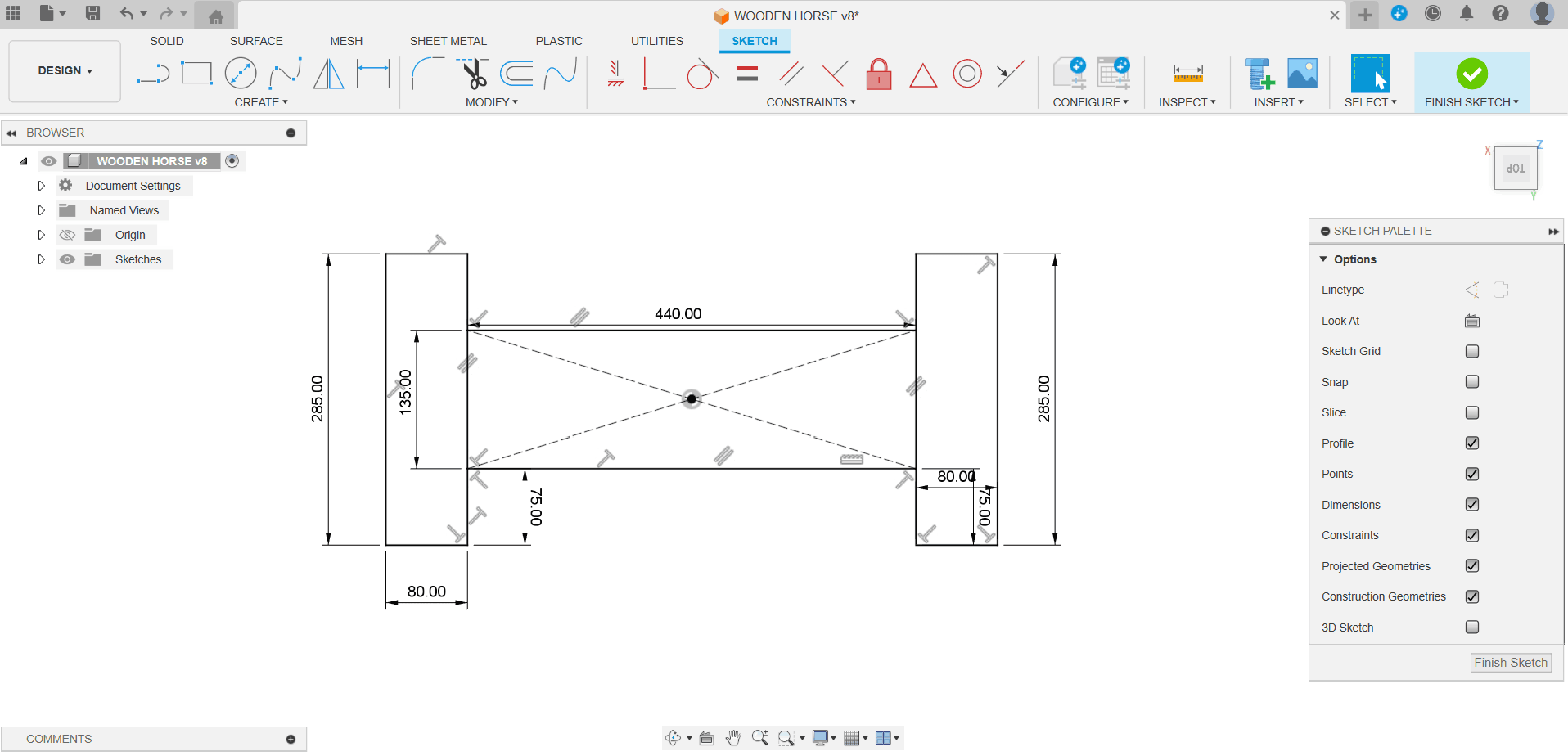
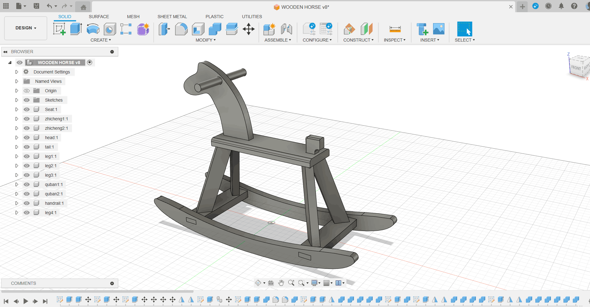
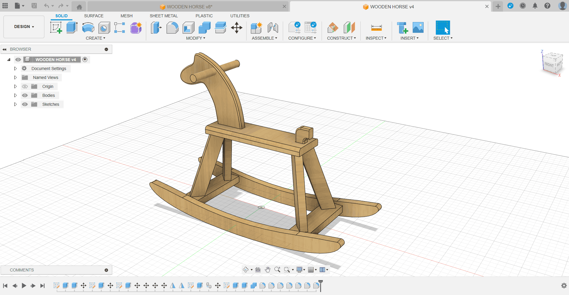
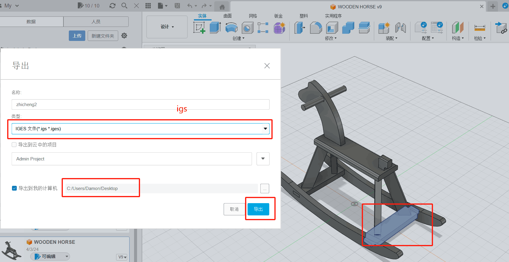
As a result of testing exercises in group assignments, I started using Fusion360 to design Trojan horses, each part of which is a separate accessory for subsequent processing.
Separation
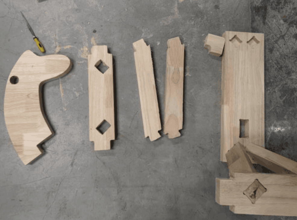
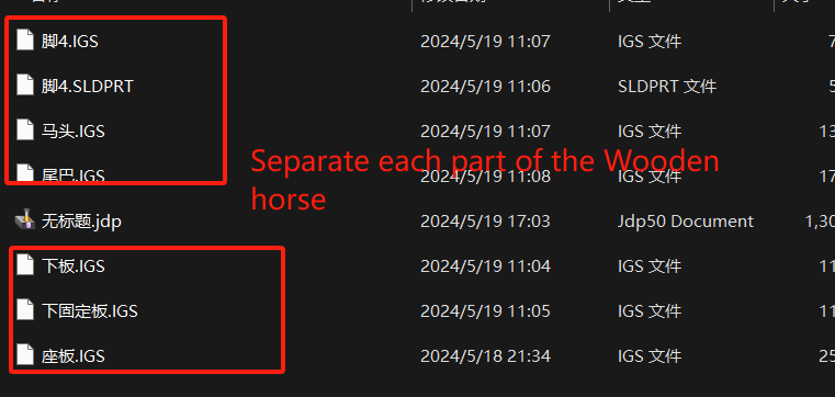
After the design is complete, we need to process the model according to the actual CNC machine used. In my model, I mainly complete two steps: 1. Separate the Trojan into multiple accessories, format IGS, and save them as independent files;2. Convert the projection of each accessory in the horizontal plane into a 2D file, the actual size is consistent with the original size.

CNC
Open and connect the machine
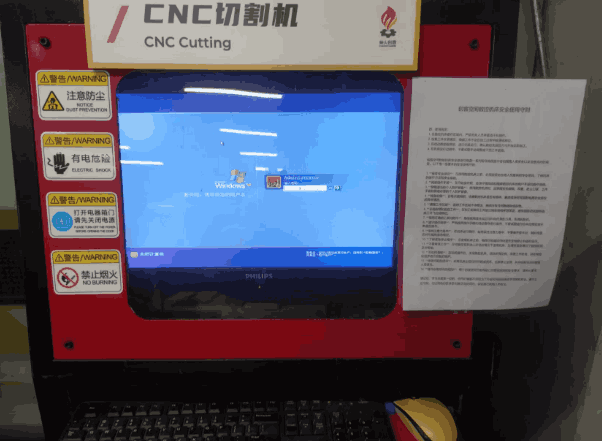
In actual use, I use a domestic CNC machine.At the Chaihuo Makerspace, this machine can only be operated using a dedicated computer (personal computers cannot be used). After turning on the computer and the CNC machine, you can directly operate the equipment, but you need to transfer the model file to be processed to this computer in advance using a USB drive. Therefore, I will copy the completed files from my personal computer to the dedicated computer.
Materials and Z-axis
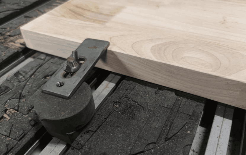
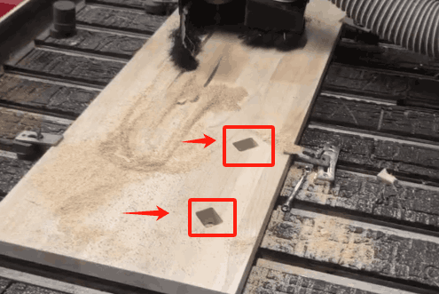
In this step, I need to complete two important tasks. First of all, we need to fix the plank material on the workbench. I used metal fittings to fix oak boards 3cm thick to the workbench. It should be noted that the board must be firmly fixed to prevent movement of the board due to vibration during processing. Then, you need to operate the software to control the movement of the tool head of the machine to the appropriate position.
- Create a processing area according to the actual board size in the software, and then set a section of the board as the xy plane origin.
- According to the material thickness (3cm), Z-axis movement is controlled by software, and the processing range is greater than or equal to 3cm.
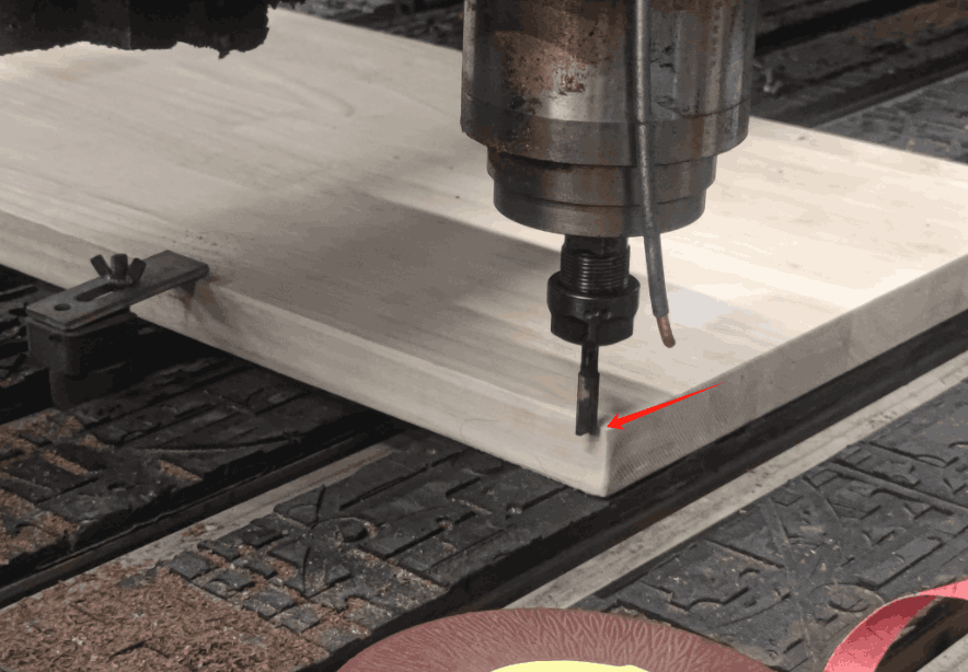
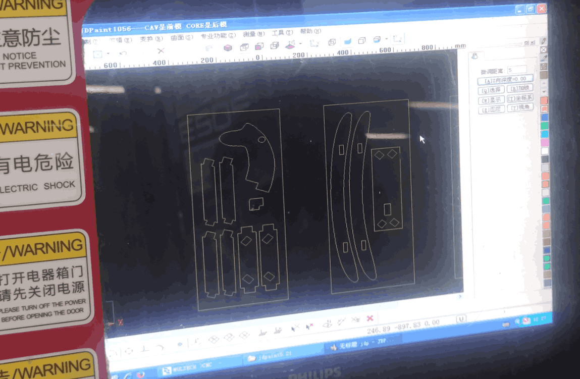
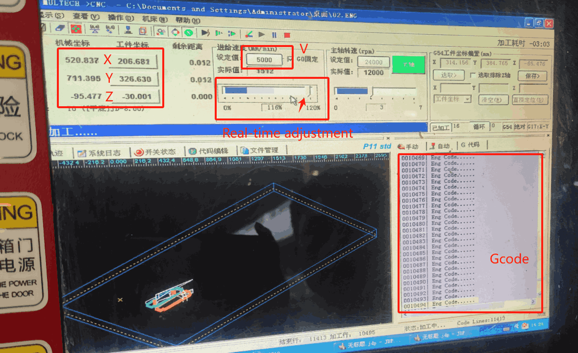
In the CNC machining process, we can generally adopt the outer contour machining or the inner contour machining method, I use the outer contour machining method, the setting speed is 5000 mm/min, and the actual speed value is automatically adjusted according to the situation. In the software we can clearly see xyz-axis data changes, tool speed and Gcode execution.
In actual processing, there are two situations where the spindle speed needs to be manually adjusted: when the Z-axis travel has reached the actual thickness of the wood (3cm), and when grooving, the speed needs to be reduced to prevent the wood from jamming and causing the entire piece to shift.
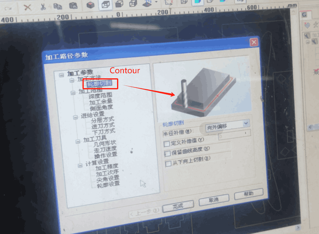
Problems
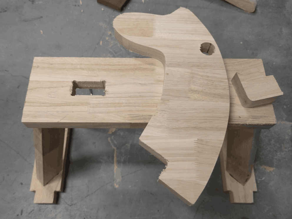
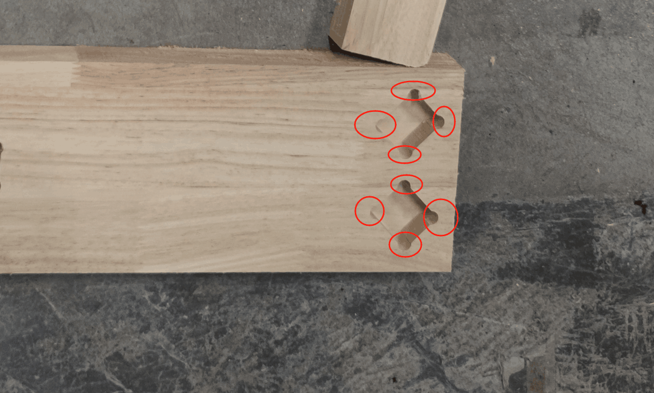
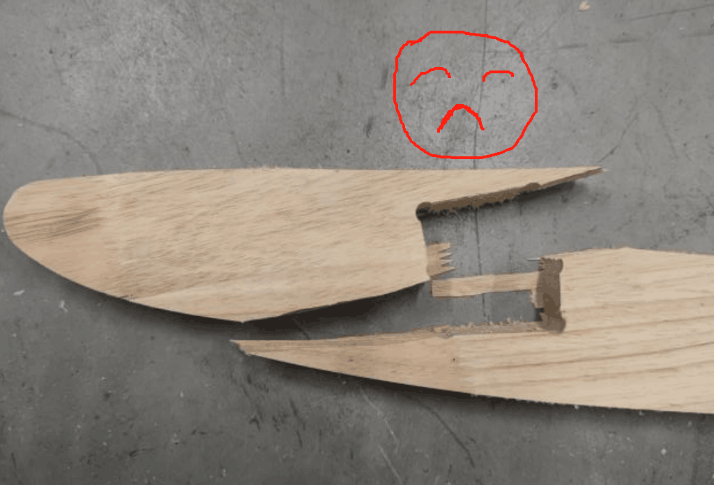
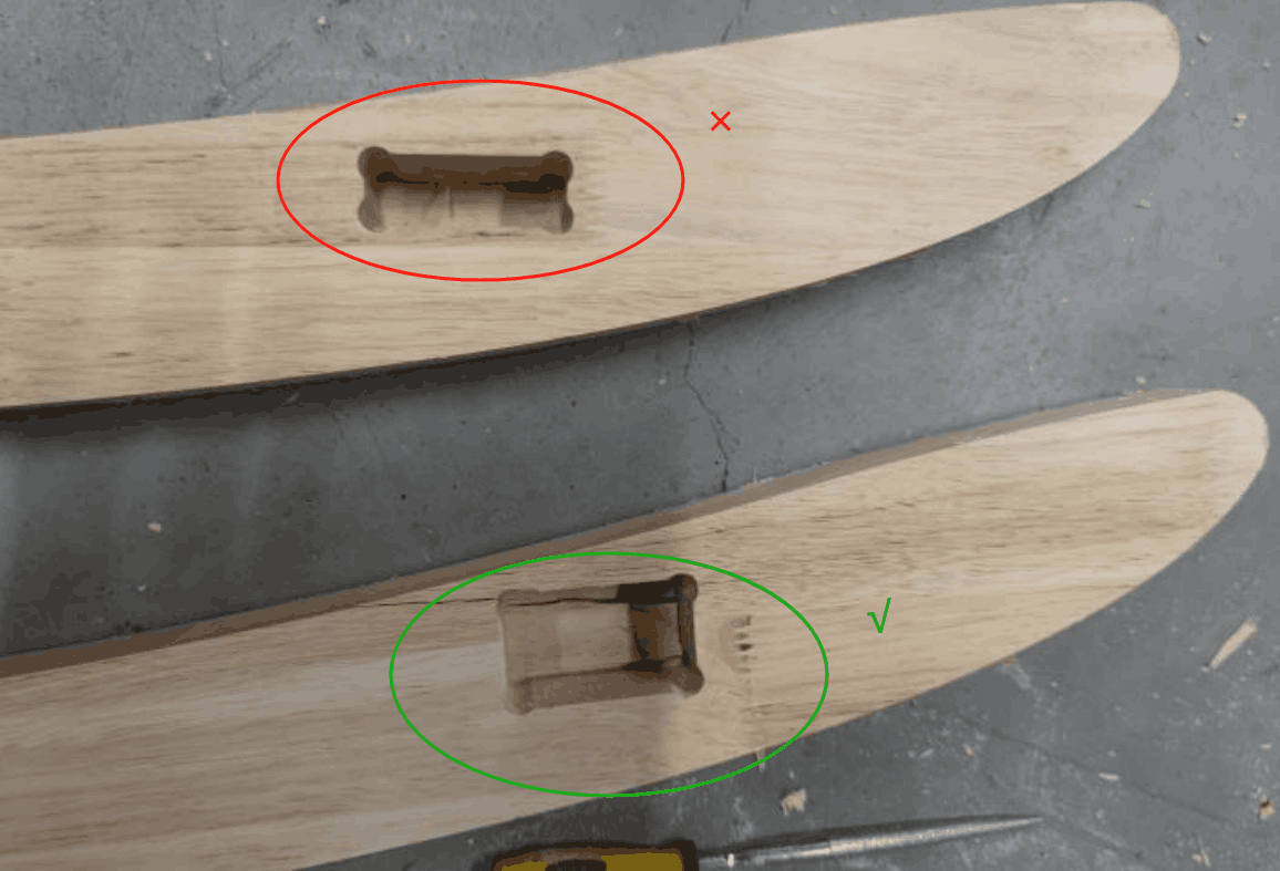
In the actual process of operation, I actually encountered some problems. First of all, the connection problem of the part structure: because at the beginning of the design model, the connection hole is set to a right angle, but in the actual machine cutting, the right angle cannot be processed, which will lead to unstable connection, so the right angle position is modified to an arc; Secondly, wood cracking, due to the hardness of the wood, resulting in fracture during the installation process, needs to be reprocessed.
Final Working
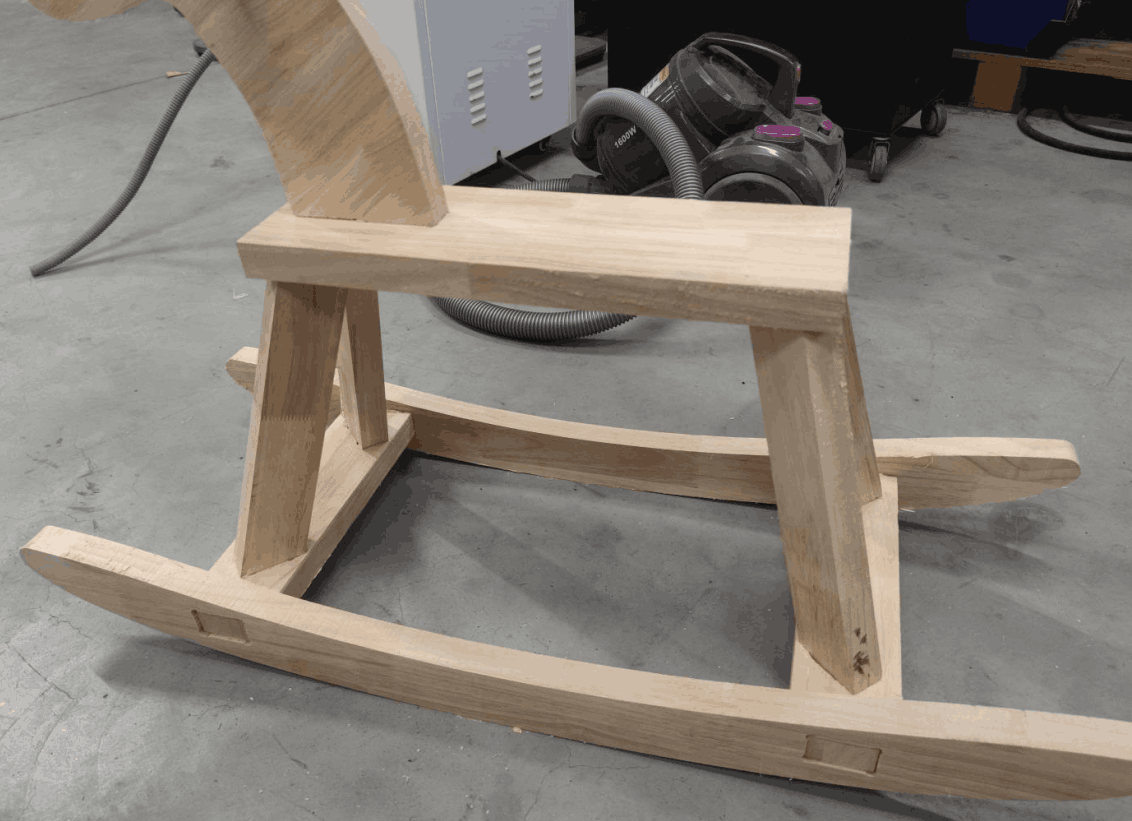
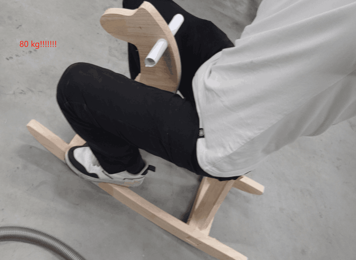
After hard work, I completed the production and installation of the whole project
