Week6. Embedded Programming
Assignments
- Group assignment:
- Browse through the data sheet for your microcontroller
- Compare the performance and development workflows for other architectures
- Individual assignment:
- write a program for a microcontroller development board that you made,to interact (with local input &/or output devices) and communicate (with remote wired or wireless devices) that could not be made subtractively
- extra credit: use different languages &/or development environments
- extra credit: connect external components to the board
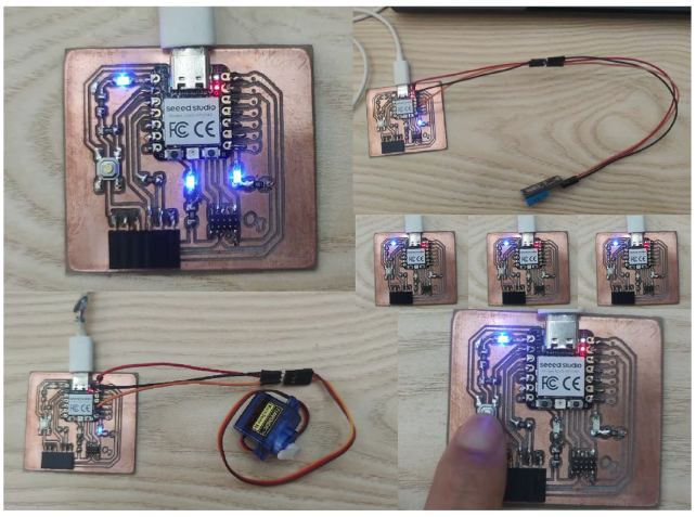
Hero Shot
Group Assignments
Comparing Micro-controllerr
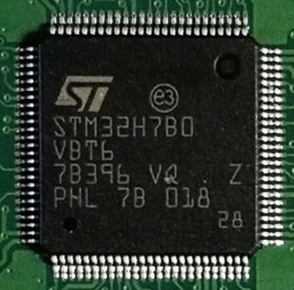
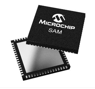
| Parameter | RP2040 | STM32 | SAMD21 | ESP32-S3 |
|---|---|---|---|---|
| Iamge | 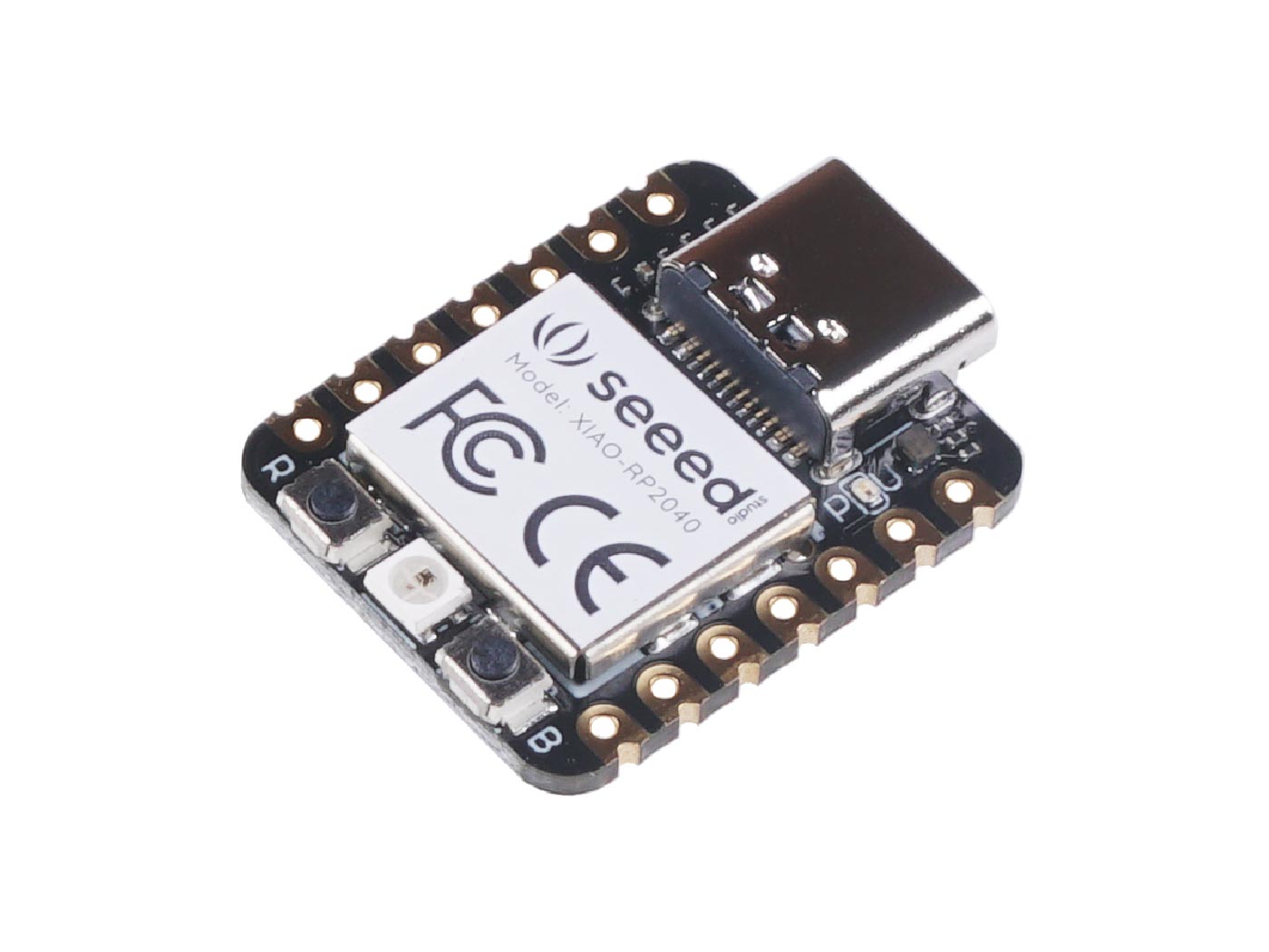 |
 |
 |
 |
| Core | Dual-core ARM Cortex-M0+ | ARM Cortex-M series | ARM Cortex-M0+ | Dual-core Xtensa LX6 |
| Max. Frequency | 133 MHz | Variable, from tens of MHz to hundreds of MHz | 48 MHz | 240 MHz |
| Memory | 264KB SRAM | SRAM from tens of KBs to hundreds of KBs, plus Flash from hundreds of KBs to MBs | 32KB SRAM | SRAM from 320KB to 2MB, plus up to 4MB PSRAM |
| Communication | SPI, I2C, UART, GPIO | SPI, I2C, UART, CAN, Ethernet | SPI, I2C, UART, GPIO | SPI, I2C, UART, CAN, Ethernet |
| Peripherals | GPIO, PWM, ADC, USB | Timers, ADC, DAC, USART, USB | GPIO, ADC, DAC, PWM | GPIO, PWM, ADC, SPI, I2C |
| Wireless | None | Optional Wi-Fi, Bluetooth | None | Wi-Fi, Bluetooth |
| Power Supply | 3.3V | Variable | 3.3V | Variable |
| Other Features | Low power, low cost | High performance, rich peripherals | Low power, suitable for battery-powered devices | High performance, Wi-Fi, Bluetooth |
My board uses XIAO RP2040 which is a micro-controller board using the RP2040 chip. The functionalities are slightly different such as an USB-C connector for programming and power supply
Reference
My Microcontroller
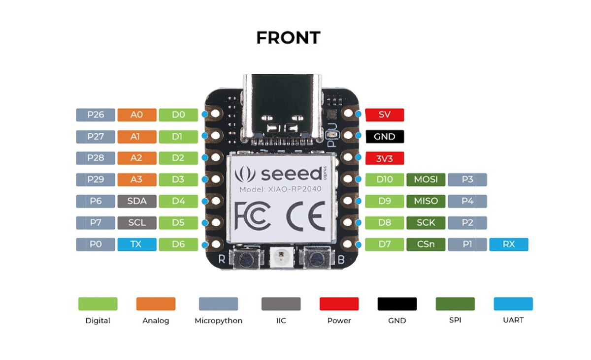
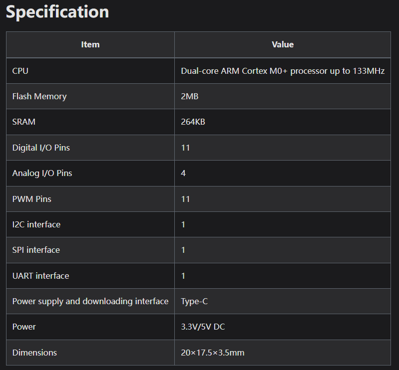
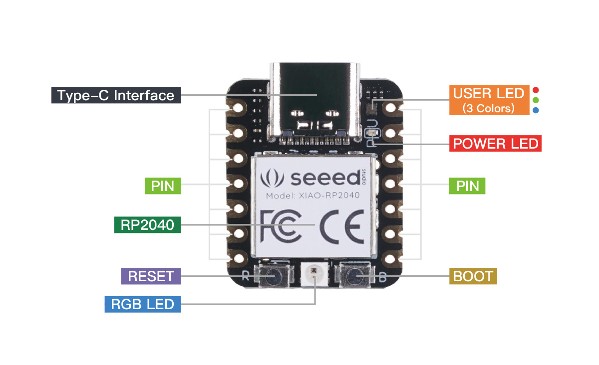
The Seeed Studio XIAO RP2040 is as small as the Seeed Studio XIAO SAMD21 but it's more powerful. On one hand, it carries the powerful Dual-core RP2040 processor that can flexible clock running up to 133 MHz which is a low-power microcontrollers. On the Seeed Studio XIAO RP2040 there is also 264KB of SRAM, and 2MB of on-board Flash memory which can provide more program to save and run. On the other hand, this little board has good performance in processing but needs less power. All in all, it is designed in a tiny size as small as a thumb(20x17.5mm) and can be used for wearable devices and small projects. There are 14 GPIO PINs on Seeed Studio XIAO RP2040, on which there are 11 digital pins, 4 analog pins, 11 PWM Pins,1 I2C interface, 1 UART interface, 1 SPI interface, 1 SWD Bonding pad interface.
Features
- Powerful MCU: Dual-core ARM Cortex M0+ processor, flexible clock running up to 133 MHz
- Rich on-chip resources: 264KB of SRAM, and 2MB of on-board Flash memory
- Flexible compatibility: Support Micropython/Arduino/CircuitPython
- Easy project operation: Breadboard-friendly & SMD design, no components on the back
- Small size: As small as a thumb(20x17.5mm) for wearable devices and small projects.
- Multiple interfaces: 11 digital pins, 4 analog pins, 11 PWM Pins,1 I2C interface, 1 UART interface, 1 SPI interface, 1 SWD Bonding pad interface.
Resources
Individual Assignments
Running Lights
In the fourth week of practice, I learned to light a light on my board and blink. Therefore, I hope that on this basis, I can light all three lights on the board and achieve the effect of "running lights".
By reading the datasheet file of Xiao seed RP2040, I confirmed the GPIO interface connected by three led lamps and completed the following procedure for testing:
            void setup() {
              pinMode(0, OUTPUT);
              pinMode(1, OUTPUT);
              pinMode(26, OUTPUT);
            }
            void loop() {
              digitalWrite(0, HIGH);
              delay(100); // Delay time
              digitalWrite(0, LOW);
              digitalWrite(1, HIGH);
              delay(100); // Delay time
              digitalWrite(1, LOW);
              digitalWrite(26, HIGH);
              delay(100); // Delay time
              digitalWrite(26, LOW);
            }
Breathing Lights
Next, I wanted to make more lighting effects to help me become more proficient with Xiao seeed RP2040, so I tried to make breathing effects with lights.
              const int ledPin0 = 0;
              const int ledPin1 = 1;
              const int ledPin26 = 26;

              void setup() {
                pinMode(ledPin0, OUTPUT);
                pinMode(ledPin1, OUTPUT);
                pinMode(ledPin26, OUTPUT);
              }

              void loop() {
                // Breathing effect from low to high to low
                for (int i = 0; i <= 255; i++) {
                  analogWrite(ledPin0, i);
                  analogWrite(ledPin1, i);
                  analogWrite(ledPin26, i);
                  delay(10); // Adjust delay to change breathing rate
                }
                for (int i = 255; i >= 0; i--) {
                  analogWrite(ledPin0, i);
                  analogWrite(ledPin1, i);
                  analogWrite(ledPin26, i);
                  delay(10); // Adjust delay to change breathing rate
                }
              }
Button and Serail
In this practical test, I am going to use both buttons and LED lights, control the LED lights by the state of the buttons, and use serial communication to display the status of the lights in the IDE's serial monitor. The following is the program I tested, which uses internal pull-up resistors to initialize the key pins. When the key is pressed, the read state is HIGH, which lights up the LED and outputs the relevant information through the serial port; otherwise, the LED will be turned off and output the corresponding information. Finally, I added a short delay to stabilize key detection
              const int buttonPin = 27;
              const int ledPin = 26;

              void setup() {
                pinMode(buttonPin, INPUT_PULLUP); // Use internal pull-up resistors
                pinMode(ledPin, OUTPUT);

                Serial.begin(9600); // //Initialize serial communication
              }

              void loop() {
                // Detect the key state
                if (digitalRead(buttonPin) == HIGH) { // LED illuminated when pin state is HIGH
                  digitalWrite(ledPin, HIGH);
                  Serial.println("LED turned on"); // Print light-on message
                } else {
                  digitalWrite(ledPin, LOW);
                  Serial.println("LED turned off"); // Print light-off message
                }
                delay(100); // Delay to stabilize key detection
              }
Servo
In addition to lights, I started trying to connect other output devices, such as the steering gear, and control the steering gear to rotate in a 0-90-180 manner.
- Connect the servo signal wire to one of the digital PWM output pins of the Xiao Seeed RP2040, I used pin 1.
- Connect the power cord of the steering gear to the 5V power supply.
- Connect ground of servo to ground pin.
              #include
              Servo servo;

              void setup() {
                servo.attach(1); // Connect steering gear to pin 1
              }

              void loop() {
                // Control the steering gear to zero degrees.
                servo.write(0);
                delay(1000); // Wait 1 second
                // Control the steering gear to 90 degrees.
                servo.write(90);
                delay(1000); // Wait 1 second
                // Control the steering gear to 180 degrees.
                servo.write(180);
                delay(1000); // Wait 1 second
              }
Temperature Alarm
In addition, I practiced reading temperature values to try to complete the function of warning according to different temperatures, here I use DHT temperature and humidity sensors, which need to use DHT library to read temperature sensor data. First, I initialize the temperature sensor and serial communication in the setup() function. Then in the loop() function, use dht.readTemperature() to read the temperature value and store it in the variable temperature. Next, it is checked whether the temperature value read is higher than a set threshold value (here, 20 degrees). If the temperature is above the threshold, the LED flashes rapidly; if the temperature is within the appropriate range, the LED remains constantly on.
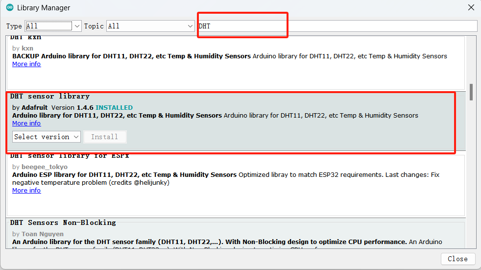
In the actual test, due to ignoring the need to install the DHT library locally in advance, the error "DHT file does not exist" was prompted. Therefore, I searched and installed the corresponding DHT library file in the admin library option. Here's the code for the successful test:

              #include
              #define DHT_PIN 1    // Temperature sensor connected to pin 1 of Xiao Seeed RP2040
              #define DHT_TYPE DHT11   // Temperature sensor model is DHT11
              #define LED_PIN 26   // LED: pin 26

              DHT dht(DHT_PIN, DHT_TYPE);

              void setup() {
                pinMode(LED_PIN, OUTPUT);
                Serial.begin(9600);
                Serial.println("Temperature alarm has started");
                dht.begin();
              }

              void loop() {
                delay(2000); // Read temperature every 2 seconds
                // Read temperature value
                float temperature = dht.readTemperature();

                // Check if temperature value is successfully read
                if (isnan(temperature)) {
                  Serial.println("Failed to read temperature value!");
                  return;
                }

                Serial.print("Current temperature: ");
                Serial.print(temperature);
                Serial.println(" degrees");

                // Check if temperature is above the set threshold
                if (temperature > 20) {
                  // Temperature is above threshold, LED blinking rapidly
                  for (int i = 0; i < 5; i++) {
                    digitalWrite(LED_PIN, HIGH);
                    delay(200);
                    digitalWrite(LED_PIN, LOW);
                    delay(200);
                  }
                } else {
                  // Temperature is within acceptable range, LED stays on
                  digitalWrite(LED_PIN, HIGH);
                }
              }
For this week's assignment, I tried to practice displaying information using serial output. comprises the following steps of: switching a lamp by using a key; outputting the switching state of an led lamp in a serial port; and outputting the temperature value of a temperature alarm in a serial port monitor in a serial port.
Other IDE: Thonny
Xiao seeed RP2040 board uses Raspberry Pi Pico and supports MicroPython programming. ThonnyIDE knew something about it from previous work experience, so I downloaded the software and updated and prepared the software according to Xiao seeed RP2040 requirements.
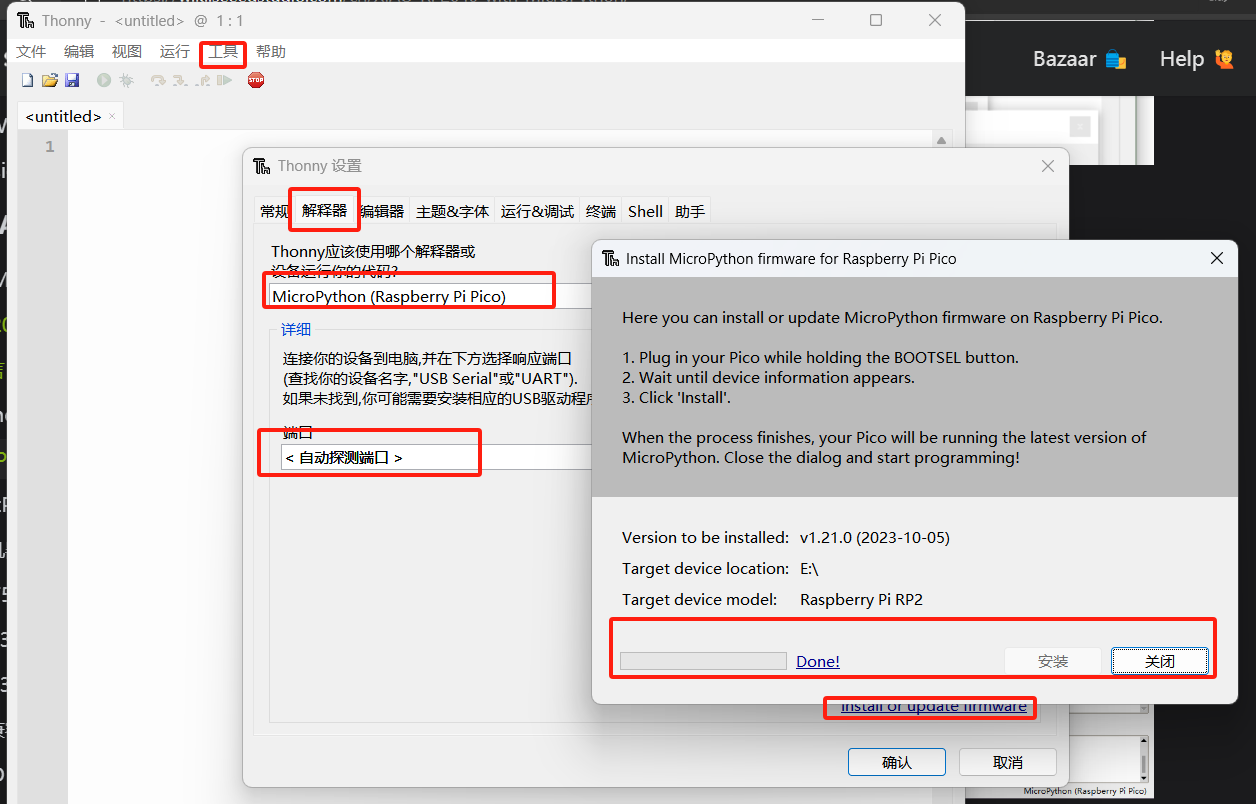
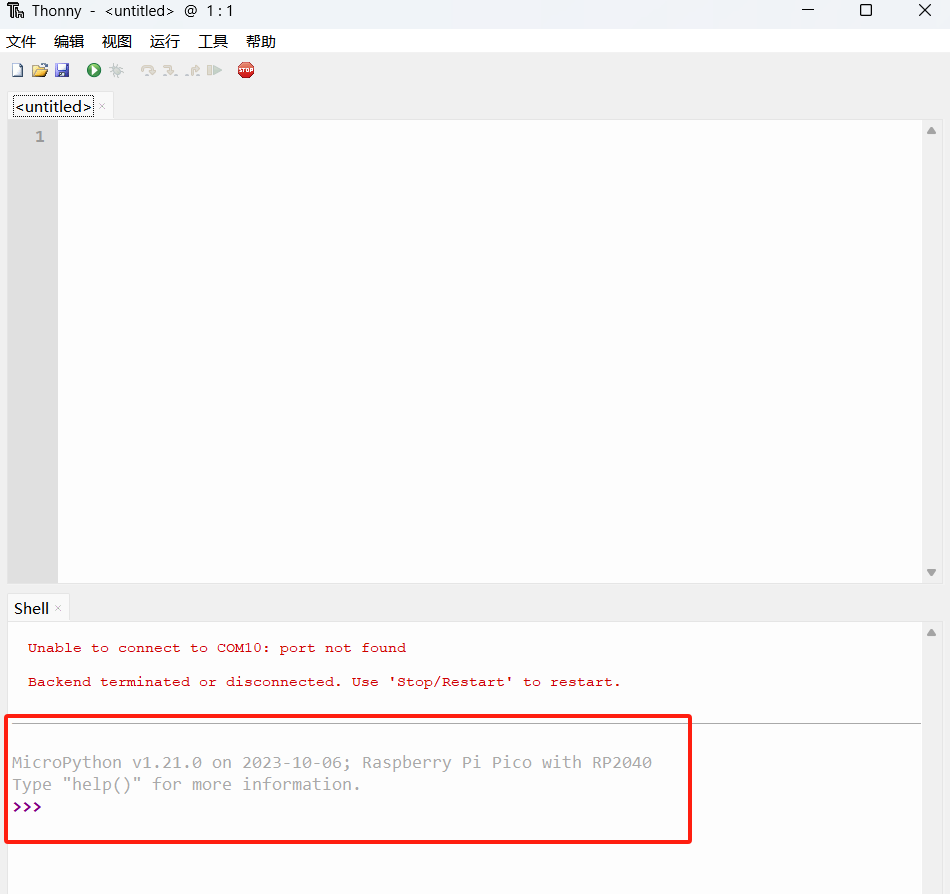
Next, I wrote the program to flash the LED light (connecting the digital pins 1 and 26).
            from machine import Pin
            import time

            # Configure Digital Pin 26 and Digital Pin 1 for output mode
            led_pin1 = Pin(26, Pin.OUT)
            led_pin2 = Pin(1, Pin.OUT)

            while True:
                # Alternating on and off LED on digital pin 26
                led_pin1.value(not led_pin1.value())

                # Alternating on and off LED on digital pin 1
                led_pin2.value(not led_pin2.value())

                time.sleep(1)  # Wait 1 second