Week5. 3D Scanning and Printing
Assignments
- Group assignment:
- Test the design rules for your 3D printer(s)
- Individual assignment:
- design and 3D print an object (small, few cm3, limited by printer time) that could not be made subtractively
- 3D scan an object (and optionally print it)
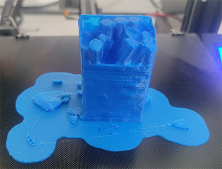
Hero Shot
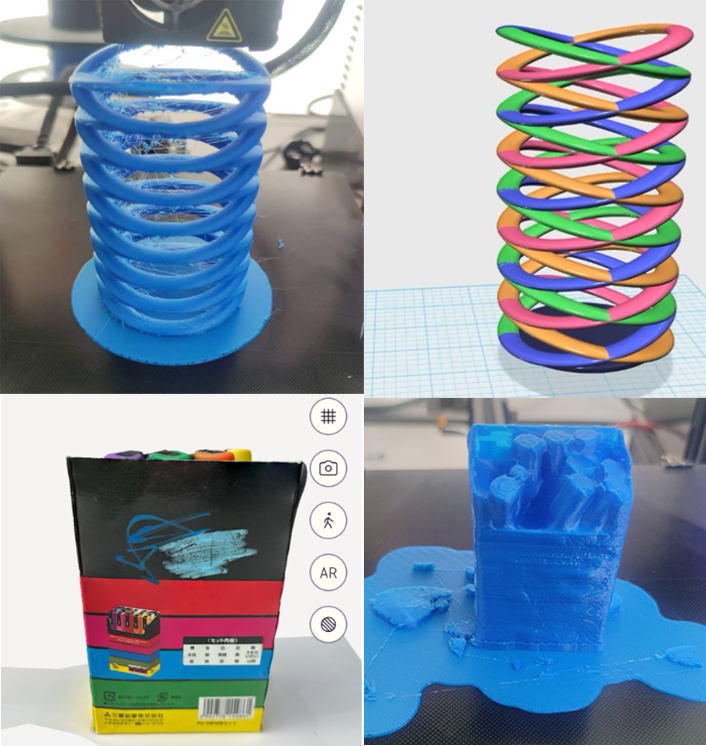
Group Assignments
3D printer
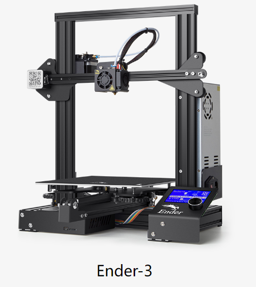
The printer I used is Ender-3.
Slice:Cura
UltiMaker Cura is free, easy-to-use 3D printing software trusted by millions of users. Fine-tune your 3D model with 400+ settings for the best slicing and printing results.
- User-Friendly Interface: Cura boasts an intuitive user interface, making it easy to learn and operate for both beginners and experienced users.
- Open-Source Software: Cura is open-source, allowing users to use and customize it freely. It benefits from community contributions and feedback for continuous improvement.
- Efficient Slicing Engine: With an efficient slicing engine, Cura can slice 3D models into printable layers, supporting various parameter settings to optimize print quality and speed.
- Support for Multiple Printers: Cura supports a wide range of 3D printers, including Ultimaker and other popular brands. Users can easily configure and manage printer settings.
- Rich Parameter Settings: Cura offers extensive parameter settings, enabling users to adjust print speed, layer height, infill density, and more to meet different printing requirements.
- Preview Functionality: Users can preview the print result before printing, including layer layout, support structures, and more, facilitating adjustment and optimization of print settings.
- Automatic Support Generation: Cura can automatically generate support structures to stabilize complex models during printing, helping to prevent deformation or collapse.
- Continuous Updates and Improvements: The Cura team regularly updates and improves the software, adding new features, fixing bugs, and maintaining close communication with users for feedback and suggestions.
What is slice?
Firstly, the main principle of 3D printing technology is based on the method of "layered manufacturing, stacking molding" to achieve rapid manufacturing of parts. Objects are designed using 3D modeling software or scanned with a scanner and saved as STL files. Secondly, import the model file into slicing software and set parameters according to the process requirements. The slicing software slices the model file into a series of two-dimensional planes with a specified thickness, which are the printer's motion trajectories. Then, send the motion trajectory instructions for each layer to the printer. Finally, the printer prints the solid model layer by layer according to the planned path, and after necessary processing, the final product is obtained.
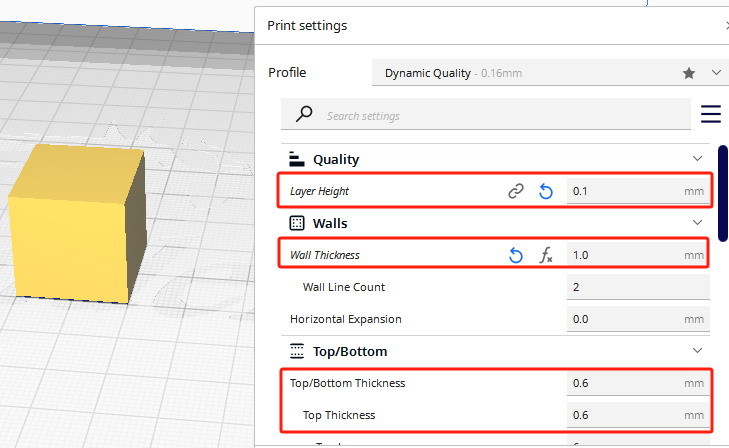
Default settings
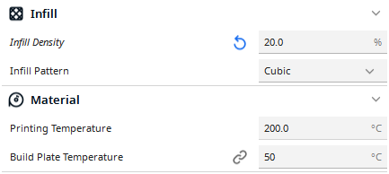
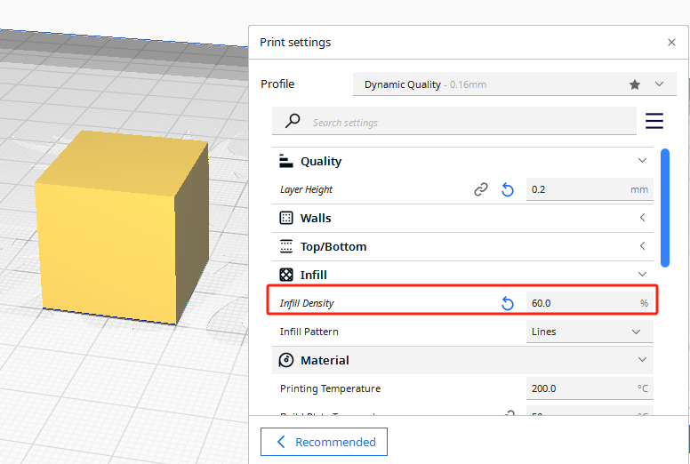
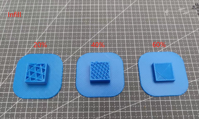
Infill
Under the premise that the layer thickness is 0.2mm, this setting fills 20%, 40%, 60%, and prints the effect.
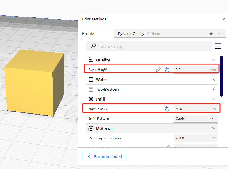
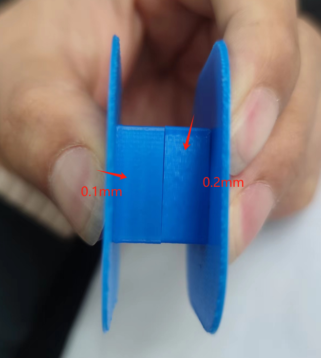
layer Height
Set two layer thicknesses: 0.1mm and 0.2mm

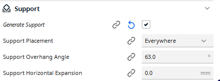
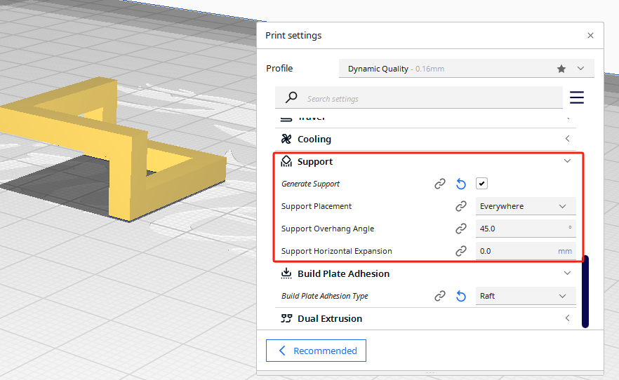
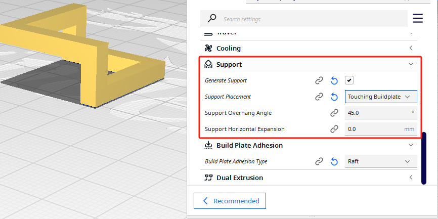
Support
Two fill patterns: everywhere\touching buildplate
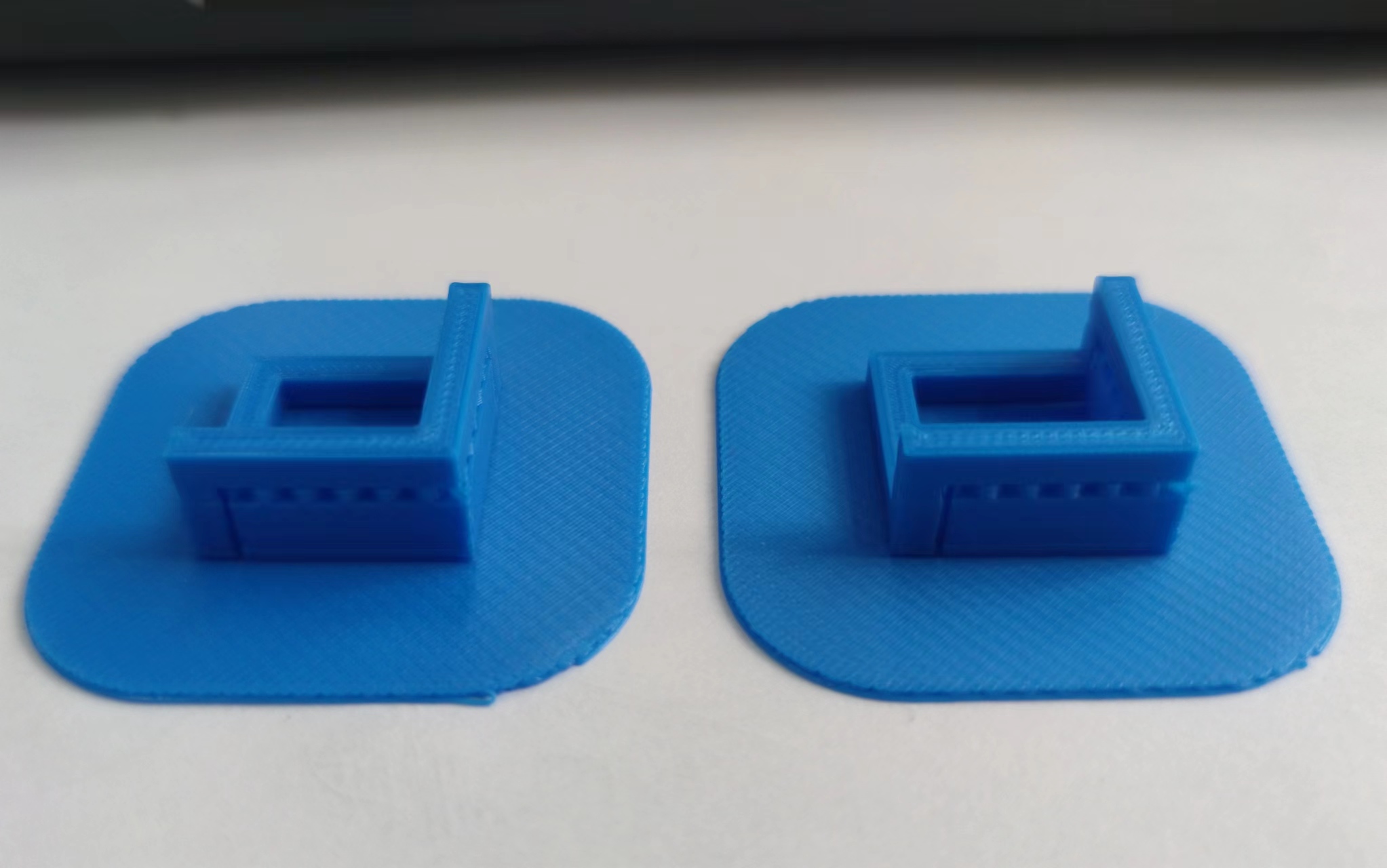
Overhangs
In 3D printing,"overhangs" refer to areas of the design that are not directly supported by support structures. In the printing process, if there is no proper support structure or the printing angle is improper, the overhang may cause printing failure or quality degradation.
When addressing this issue, we typically employ software to automatically add support structures, adjust printing directions, and minimize overhang angles. Adding support structures: You can set an angle threshold in the slicing software. If the angle exceeds this threshold, support structures are added. Adjusting printing direction: Generally, we can invert the XYZ axis in the slicing software to reorient the object and reduce overhangs. However, in this test model, overhang issues persist regardless of orientation adjustments. Reducing overhang angles: This approach is useful for models with protruding structures. Yet, in this test model, adjustments fail to mitigate overhangs. Therefore, the optimal solution is to add support structures.
what I learned?
In practical application, I can set filling, support and layer thickness according to actual design needs. For filling parameters, we can set different filling densities to control printing time, the higher the density, the higher the printing time, but the better the quality of printing; for layer thickness, the smaller the thickness of each layer, the finer it means, the more time it takes, but it needs to be set according to the actual situation of the machine.
3D Object
Software: 123D Design

123D Design is a 3D modeling software developed by Autodesk to enable users to easily create and edit 3D models. The software provides an intuitive user interface and rich tools that enable users to perform a variety of 3D design tasks, including prototyping, product design, building models, and more.
Here are some of the key features of 123D Design:
- Intuitive interface: 123D Design has an intuitive user interface that allows users to quickly get started and start creating 3D models.
- Rich tools: The software provides a variety of tools, including drawing tools, modeling tools, editing tools, etc., to meet the user's various design needs.
- Multiple import and export formats: 123D Design supports import and export of multiple file formats, including STL, OBJ, STEP, etc., so that users can easily interact and share with other software.
- Free to use: 123D Design is free software that users can download and use for free, suitable for beginners and amateurs to do 3D modeling and design.
***Warning:Autodesk 123D Design has been discontinued as of March 31st 2017. It is no longer available for download from the official site and already downloaded versions will no longer be supported.
Step1
(1) Select Menu—Sketch—Polyline, and draw a line segment of any length on the workspace; Choose Menu—Primitive—Torus, and create a torus on the workspace with one endpoint of the line segment as the center, with a major radius of 40mm, and a minor radius of 5mm; (2) Divide the torus into two semi-toruses, use the Split tool, select Menu—Modify—Split Entity Command, then select the entity to be split as the torus, and the splitting tool as the line segment; After selecting the splitting tool, a red splitting plane will appear, click OK in the blank area to confirm; (3) Select each of the two semi-toruses and rotate them horizontally by 30° and -30° respectively; (4) Use the Attach tool to attach the two parts together, select Menu—Attach, and select the cross-sections of the two entities on one side each.


Step2
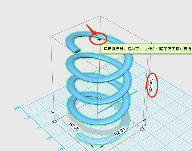
(5) Select the created entity, choose Menu—Merge Command, and merge the two parts into one whole; Select the merged whole, then press Ctrl+C (copy) and Ctrl+V (paste) in succession to quickly duplicate and create another entity, and move it upward a certain distance; Use the Attach tool to attach the cross-sections of the two wholes together; (6) Repeat the above steps 2-3 times (you can increase the number of repetitions); Then select the created entity, choose Menu—Transform—Smart Scale, click on the top center point, and move it downward to 140mm; Click ✔ to exit when finished.


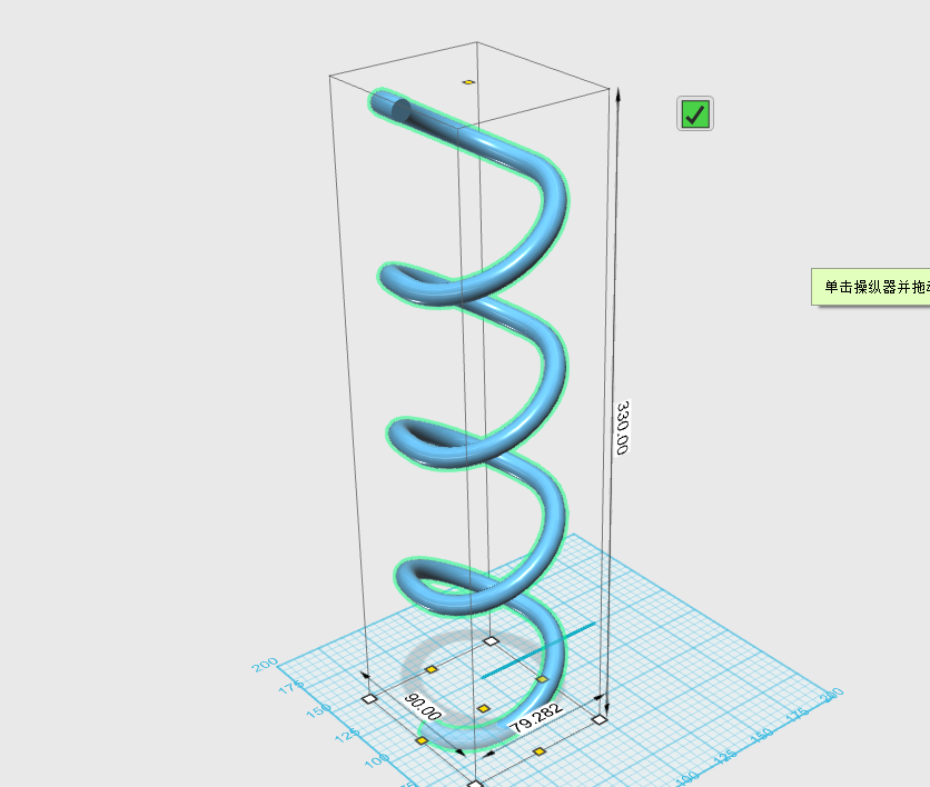
Step3
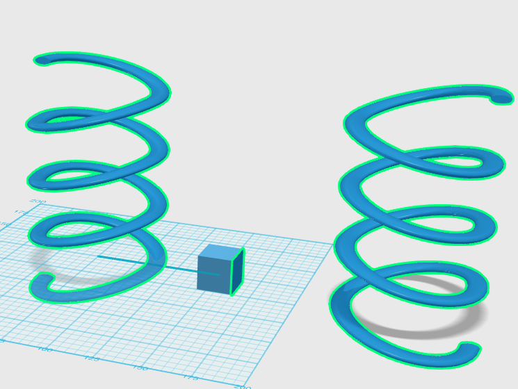
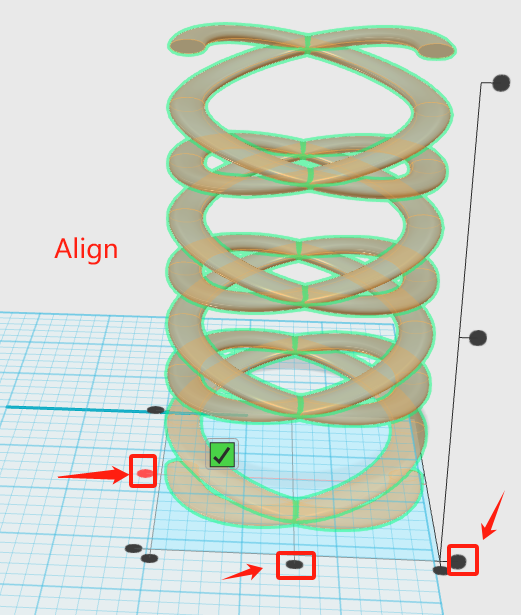
(7) Select Menu—Primitive—Cuboid, and create a cuboid of any size next to the entity; Choose Menu—Array—Mirror Command, then select the entity as the spiral entity, and the mirror plane as the side of the cuboid, to create another spiral entity; (8) Select the two spiral entities, choose Menu—Transform—Align, horizontally align the two entities, and align the bottom faces vertically as shown in the diagram; (9) Select the two spiral entities, then press Ctrl+C (copy) and Ctrl+V (paste) in succession to quickly duplicate and create the same entities, then rotate them horizontally by 180°.

Step4
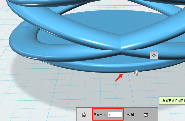
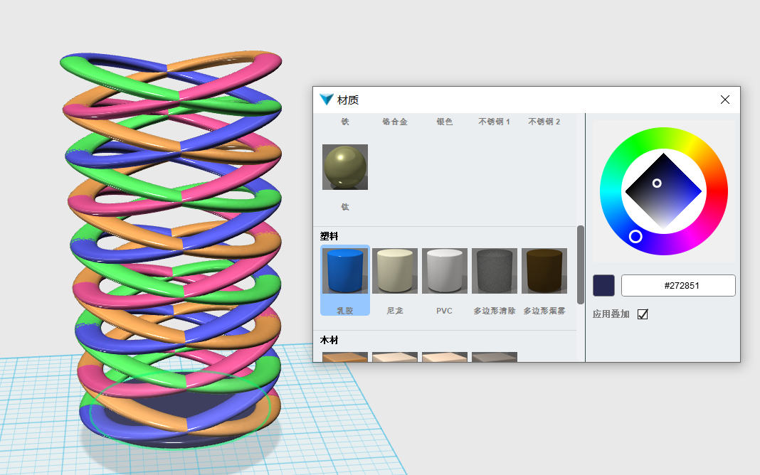
(10) When designing and creating the spiral structure of the pen holder body, the major radius of the torus is set to 40mm. To create the bottom of the pen holder, choose Menu—Primitive—Cylinder, with a radius of 35mm and a height of 3mm; (11) Select the created base and the body of the holder, choose Menu—Transform—Align tool, align them horizontally centered and vertically downward; (12) Select different parts of the artistic pen holder and adjust them to your preferred color and material.

My Working
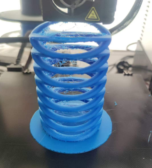
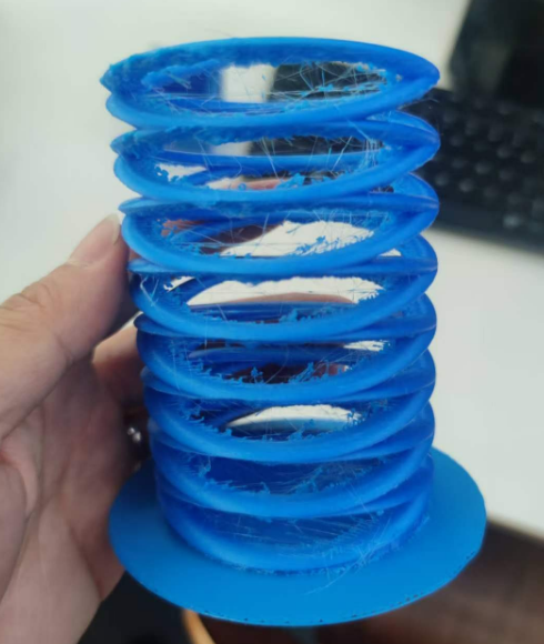
However, after printing the pen holder using a 3D printer, the result revealed the limitations of 3D printing technology. When facing issues like excessive holes or support structures between the layers, and curved contact surfaces, the 3D printing process generated excessive filament structures. These extra materials significantly affected the aesthetics.
Stringing
Stringing is an important problem in the printed model.This mostly happens as the nozzle moves through an open space rather than along the surface of the print.There are three reasons: temperature, speed, retraction settings.In the article 'How to Fix Stringing in 3D Prints', we can try to find solutions and continuously improve the printing results. I would like to thank my international mentor for their help. After analyzing the printed model, temperature appears to be a significant factor. Due to the extended printing time, the cooling efficiency of the fan decreases under sustained high temperatures, causing the actual temperature of the nozzle to be higher than the set value. Reducing the temperature appropriately might reduce stringing.
Subtractive manufacturing is a manufacturing method that removes material to create desired shapes and structures. This approach is the opposite of additive manufacturing (e.g., 3D printing), which builds objects by adding materials layer by layer.However, the pen holder I designed is not suitable for subtractive manufacturing. The pen holder has a multi-layered ring structure, and the rings are intertwined with a certain curvature, making it impossible to process with subtractive manufacturing tools. Additive manufacturing, on the other hand, is an excellent solution.
Attention
This week, the number of uploaded images and videos increased, and their sizes were too large, resulting in upload failures. Therefore, I used the FreeCompress tool to address this issue, which successfully resolved the problem.
3D Scan
Software:Polycam-LiDAR3D
There are already many 3D scanning products and software on the market that can support industrial and educational applications, and the price is more expensive, and there is a certain threshold for technical requirements. So, is there a software tool for anyone to support 3D scanning? From this point of view, I learned about an APP that supports scanning of a variety of scenes such as single objects, environments, buildings, etc., and can support the export of most file formats, which can easily import scanned models into software for modification.To do this, you just need an app!!!
How to use it?
1.Select:an Object
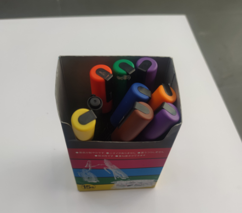
First, you need an iPhone and a specific object to scan.I chose a colorful carton and colored pen as the scanning object
2.Scanning
Next up is scanning objects. You can think of it as using the phone's camera and sensors to rotate around the target object, taking as many photos as possible during the rotation, and the more photos, the more accurate the final model.After opening the software, start moving slowly around the object for one week, and the software will automatically measure each angle of the object during the movement.
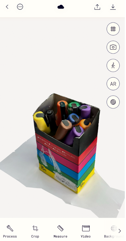
After scanning, the software will perform modeling processing, which will take a few minutes, and you can expect modeling results. Once the process is complete, we will be able to see the model in the software interface, where you can rotate the model to view it from different angles and check whether there are any errors in the model.
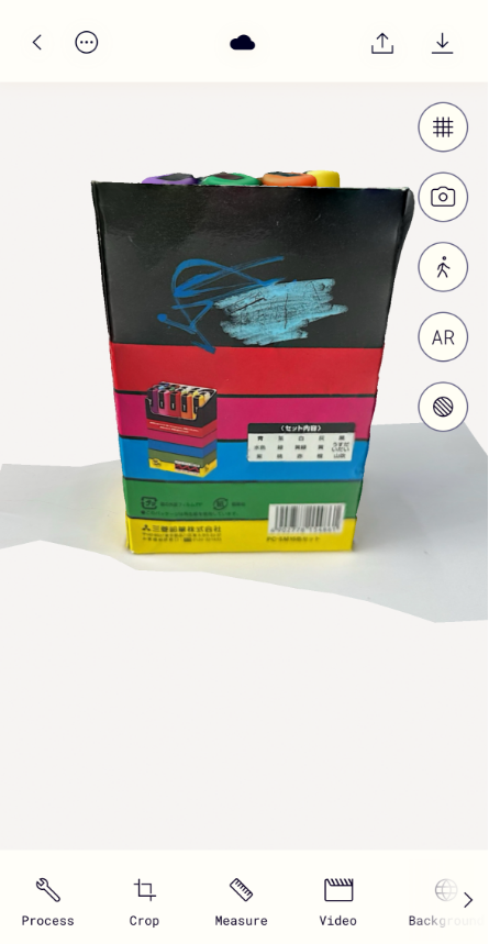
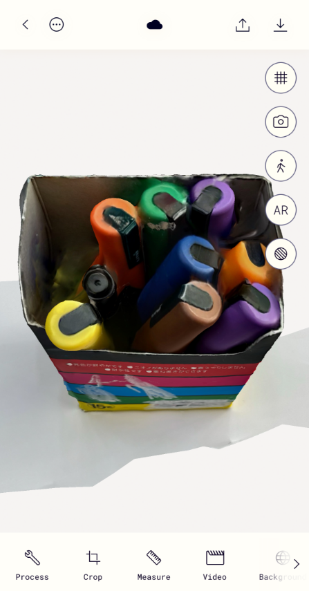
3.Export:the files you need
Finally, you have your ideal model file!Congratulations!!! You can choose the file format you want to export. Most popular 3D file formats are supported.I chose to export both stl and obj formats and import them into Tinkercad and Blender for testing and modifying the excess.
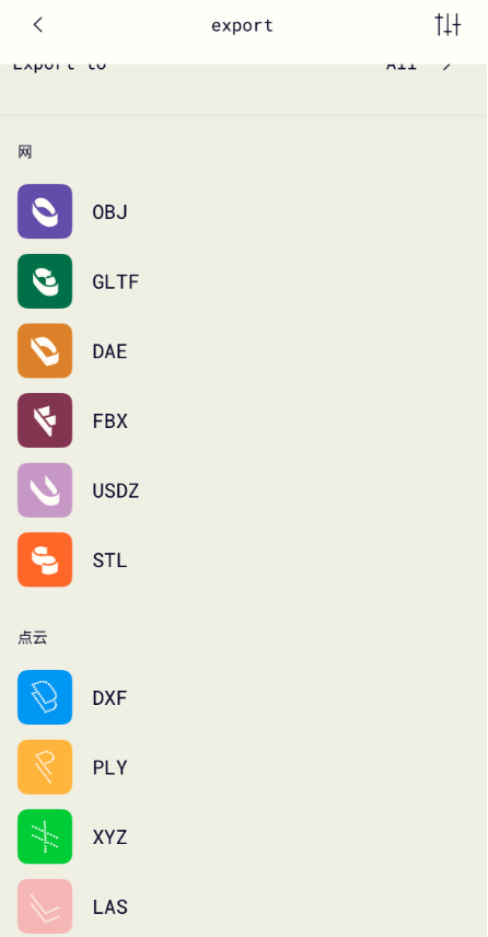
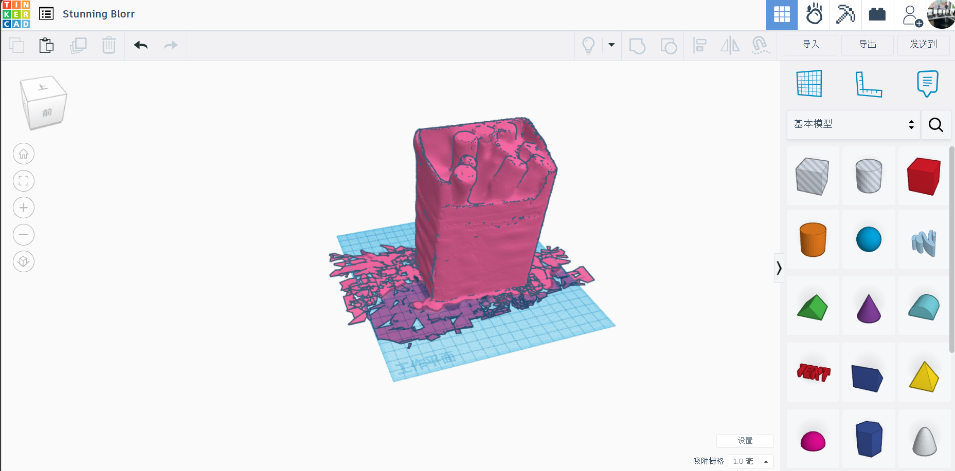
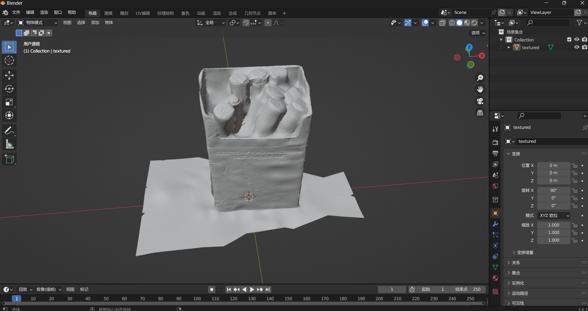
4.Printing
After processing the model, print it out using a 3D printer. What we need to know is that the model obtained after scanning the target with software shows the effect of the map of the model. The exported file format does not have a map file, so the effect turned on in soft armor is white model effect. After modifying the model in the software, you can set the map.
