Week4. Electronics Production
Assignments
- Group assignment:
- Characterize the design rules for your in-house PCB production process.
- Individual assignment:
- Make and test a microcontroller development board.
- Extra credit: personalize the board.
- Extra credit: make it with another process
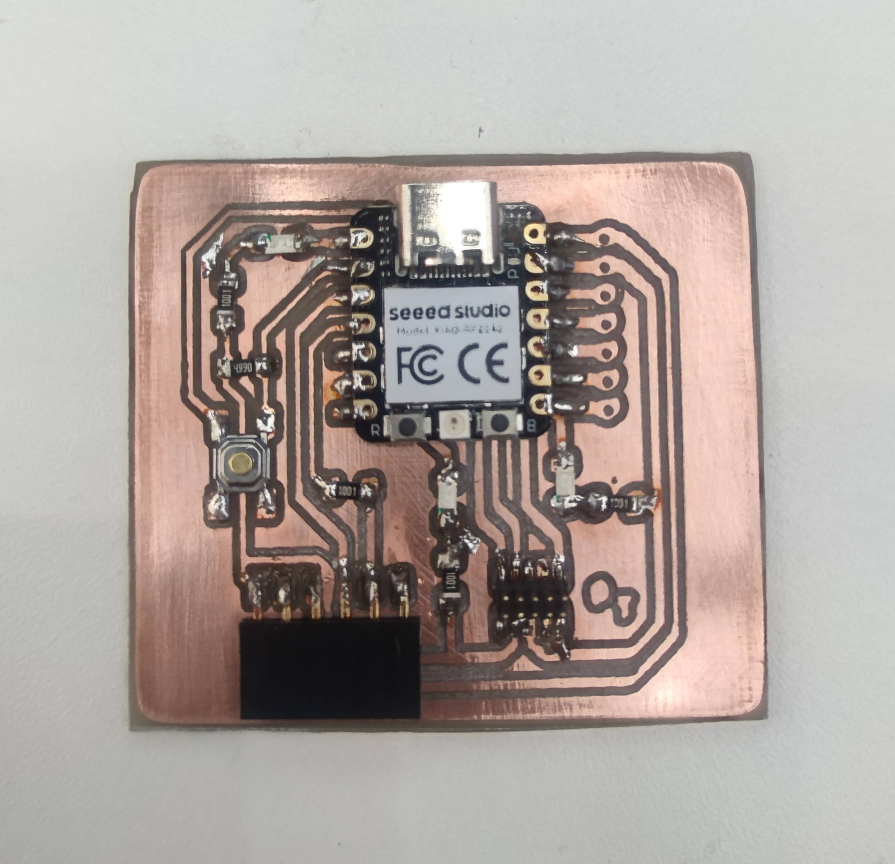
Hero Shot
Group Assignments
To describe our internal PCB production design process, I decided to test using the lab's snapmaker original.
Files
First, download pcb file from the course document, select EDA to open pcb file and export it to PDF format; then use Photoshop to process the file and export the required png format file.


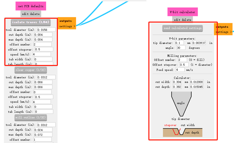
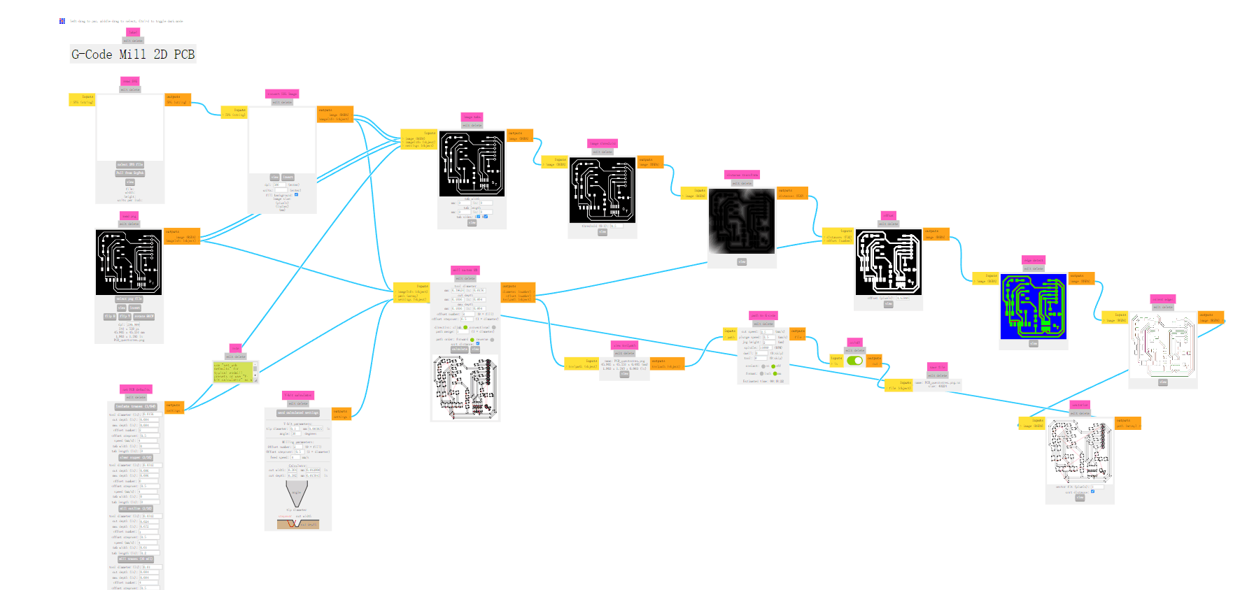
Next, I use mods project to generate track files. Selecting program->open program->mill 2D PCB will create a tree-like project settings file.


Upload the PNG image prepared and set it according to the specific information of the tool head.
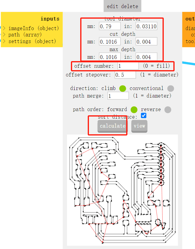
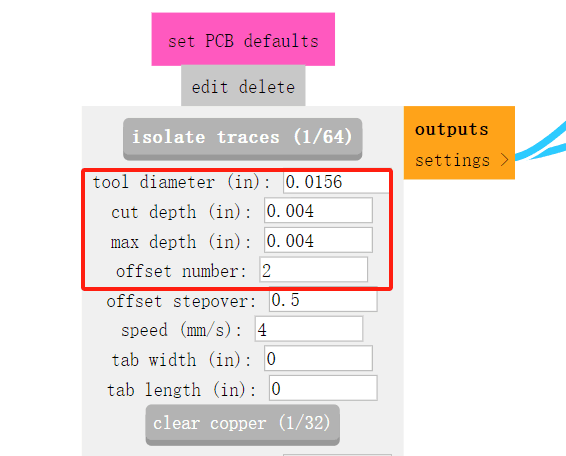
Select cutter head 1/64 size, set cutter head diameter and maximum cutting depth, click calculate to complete path file generation.

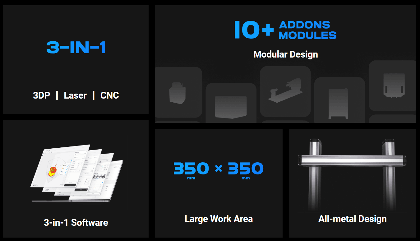
CNC Machine:Snapmaker Original
Small 3-in-1 3D printer capable of 3D printing, laser engraving and CNC engraving. click here
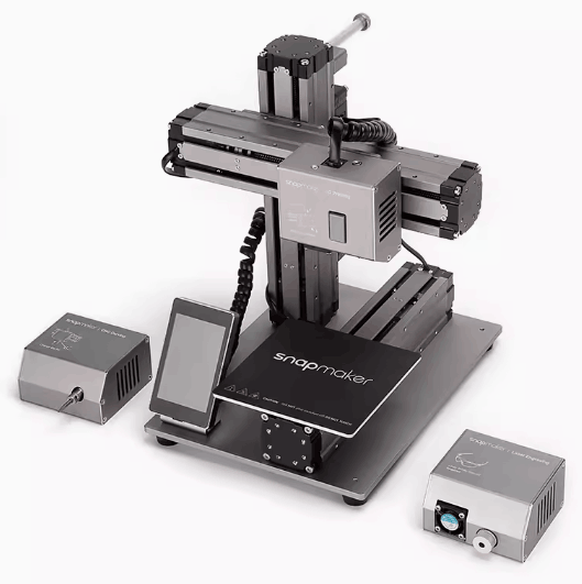
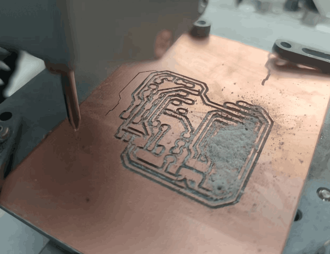
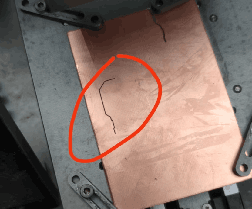
Some photos for testing
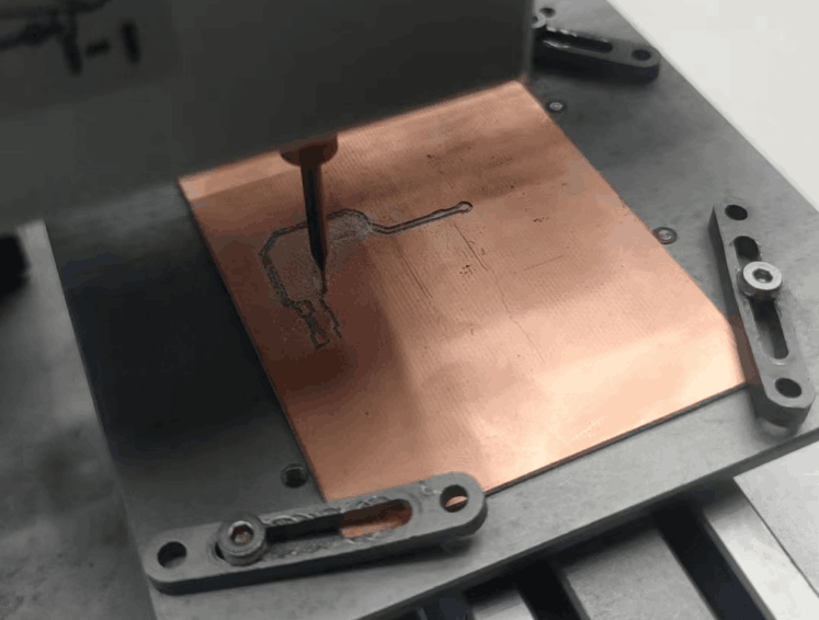
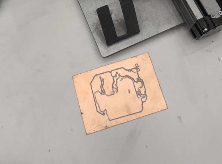
Software:Snapmaker-LUBAN
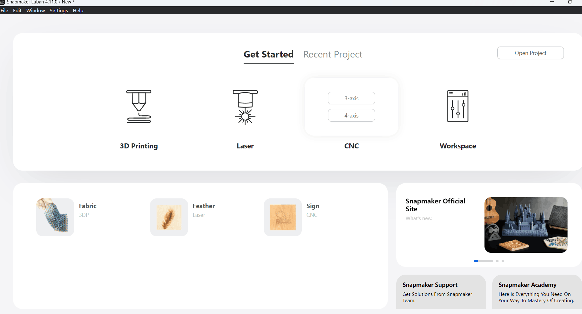
Snapmaker Luban is a free, open source CAM software developed by Shenzhen Snapmaker Technologies Co., Ltd. It is specially designed and optimized for Snapmaker machines, offering in-depth control over 3D printing, laser engraving or cutting, and CNC machining. Utilizing the three functions is made as easy as clicking a few buttons. Luban provides computer programming and software design services for hobbyists and professionals into DIY and craft. Software updates and maintenance are implemented regularly for enriched features, streamlined workflow and improved user experience.
Individual Assignments
Gerber to PNG
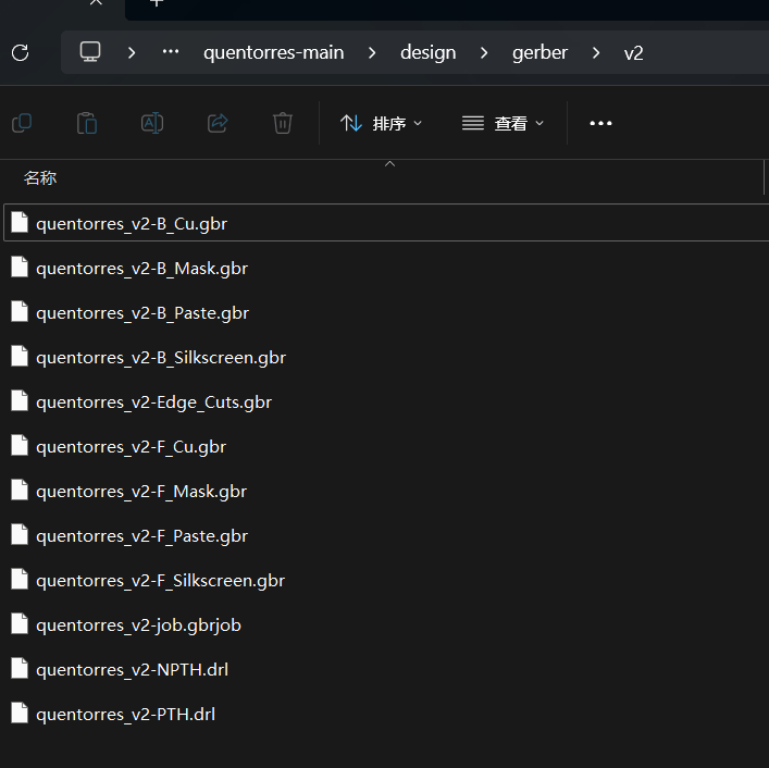
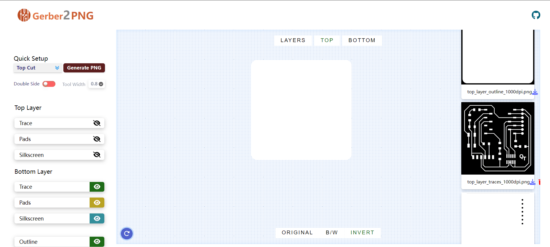
In fact, we can export the png image of PCB board for milling PCB board through EDA tool, and also can convert it through an online tool-Gerber2PNG. The operation method is as follows: Download or export the gerber file of PCB board through EDA, and then import all the files directly into Gerber2PNG tool, and then select the png image to be generated once on the left side; finally download the png image.
This tool is a very useful tool, able to directly export dpi1000 png images, solve the problem of trace jitter in the milling process.
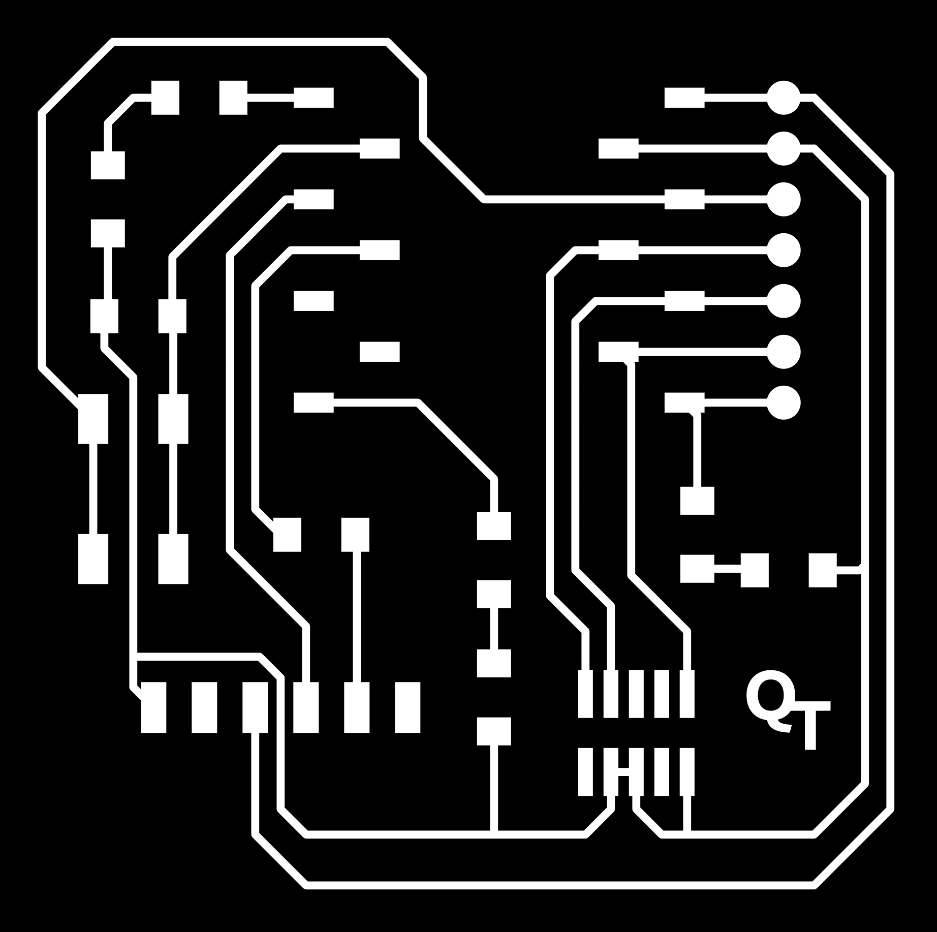
PNG files


Drilling
I chose mods project software to generate the G code path code.Why set offset to 1? The main reason is that when I use the default parameters, the output file fails quickly at cut time, and when I adjust it to 1, every milling is close to success.

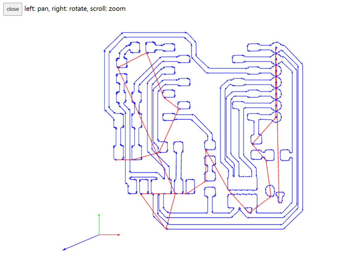
Open Luban software and import Gcode file. Use usb cable to connect machine and computer, both connected through serial port. Select the Gcode file, set the origin of the adjustment work.
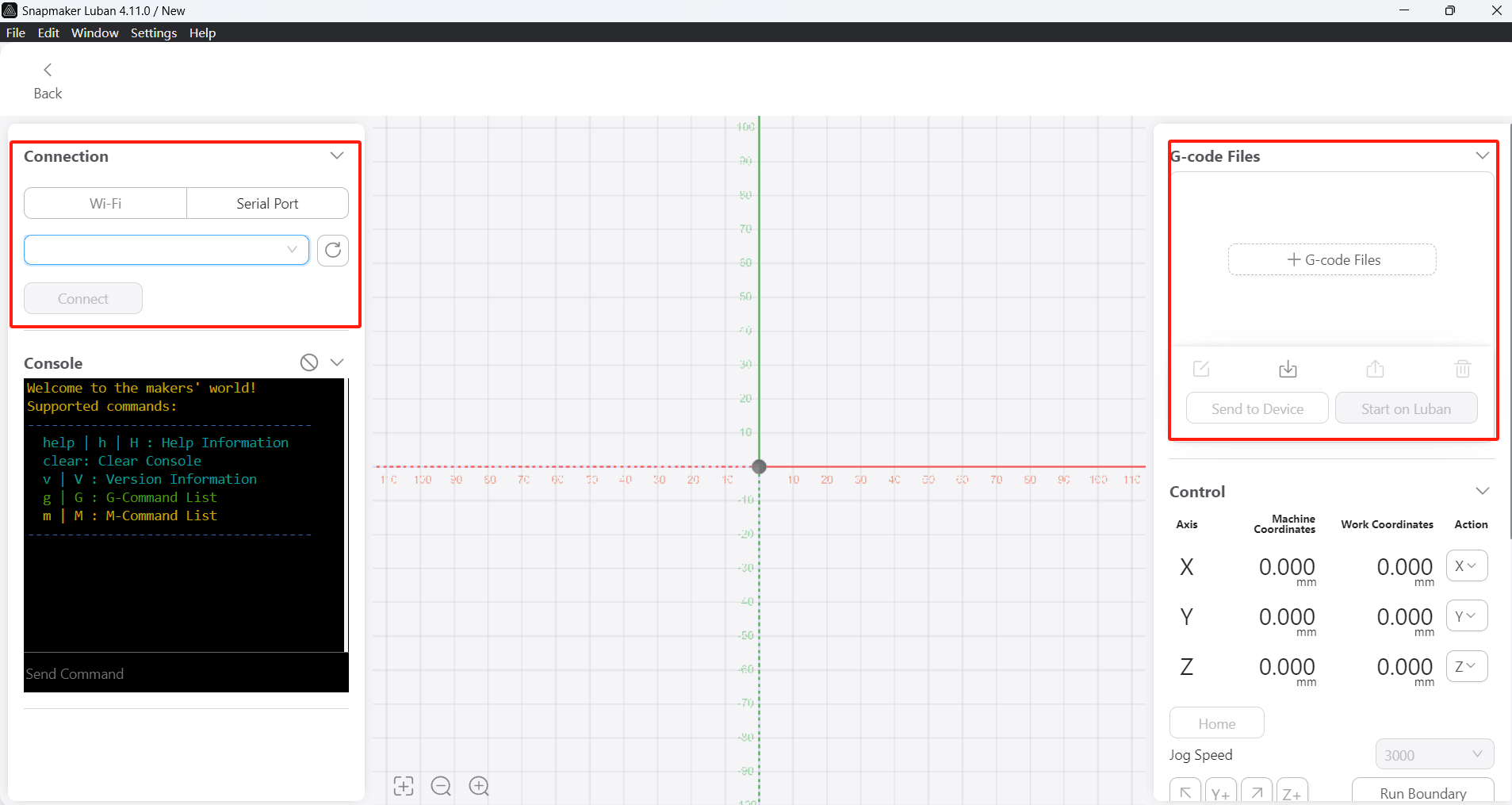
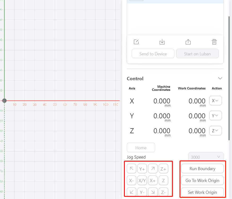
After connecting the machine to the software and importing the G-code, it is necessary to level the cutter head. Since the machine is now connected to the software, I can operate it directly through the buttons on the control software. By previewing the milling file, we can determine that the position of the cutter head is at the coordinate origin and the milling pattern is in the first quadrant, so we need to adjust the cutter head to ensure that the cutter head is in the correct working range when it starts working. We can move the axis by moving x,y,z and set it to the origin. The z-axis adjustment needs to be especially careful. This machine does not have sensor equipment to ensure proper adjustment, so it is necessary to set the distance of z-axis single movement (10mm, 1mm, 0.5 mm) to adjust slowly.

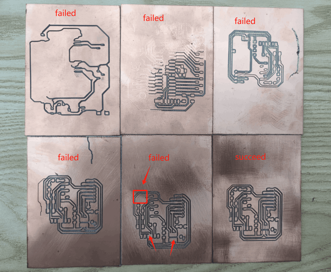
Failed Results
I chose to test two blade size, one is 0.8mm diameter, the other is 0.4mm diameter. When 0.4mm was used for testing, it would not work properly due to excessive vibration, so it was changed to 0.8mm diameter.
Because it is the first time to use the machine to make a circuit board, I am not familiar with all aspects of the machine and the performance of the tool bit, and I have damaged the very tool bit and failed very many times.
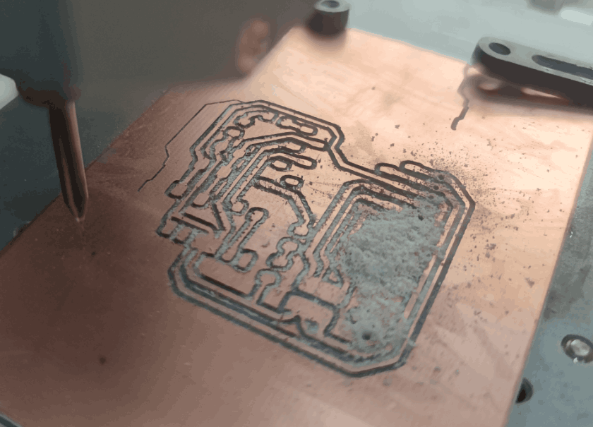
In these failed PCB boards, there are some problems: the tool head suddenly breaks; the platform level has problems, resulting in deep and shallow milling marks; the pin positions of the components are not milled out.After many attempts, the most successful PCB board was selected.
Successful Results
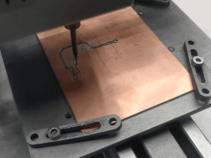
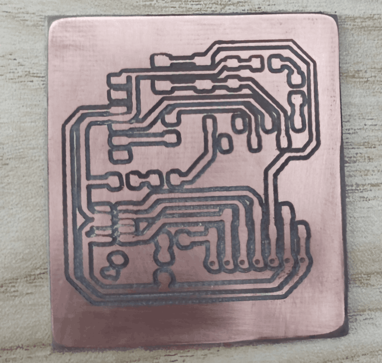
Finally, after adjusting the parameters again and again, the first successful circuit board was finally produced.
However, there are still some problems, such as unstable milling marks. Based on the advice of the international instructor and the machine used, the main causes may be the low dpi of png images and poor machine stability.
Welding
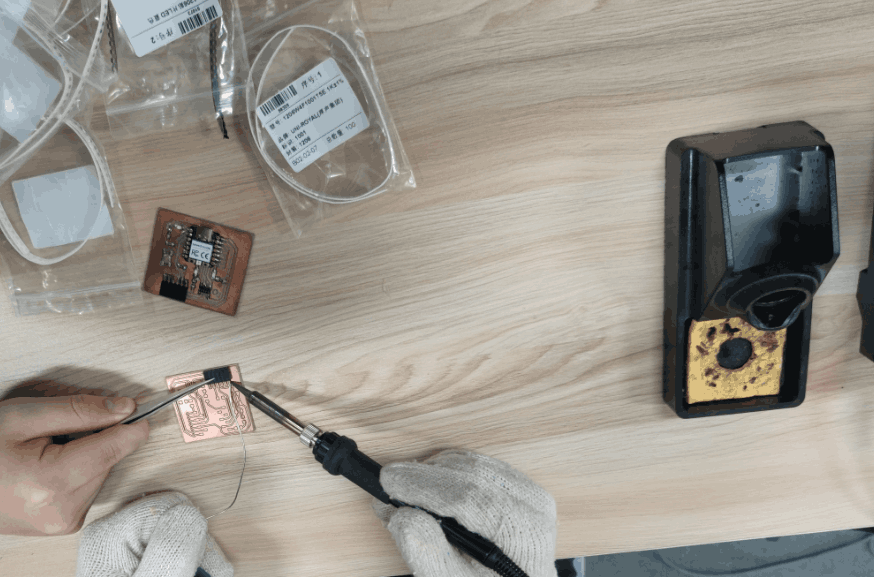
I prepare the soldering components and soldering tools and start soldering. Due to the small size of the components, extreme patience is required in this step.When soldering, first melt a bit of solder on the soldering iron, then use tweezers to hold the component in place on the PCB. Next, use the soldering iron with the melted solder to solder the component's connection points. Initially, due to not mastering the technique, the solder often failed to secure the components. After some attempts, I discovered that it is necessary to heat the corresponding position on the PCB. When the temperature rises, the solder melts better and secures the component more effectively.

Test My Microcontroller
First I go to file->preferences and put this URL in the additional boards manager URLs:
https://github.com/earlephilhower/arduino-pico/releases/download/global/package_rp2040_index.json
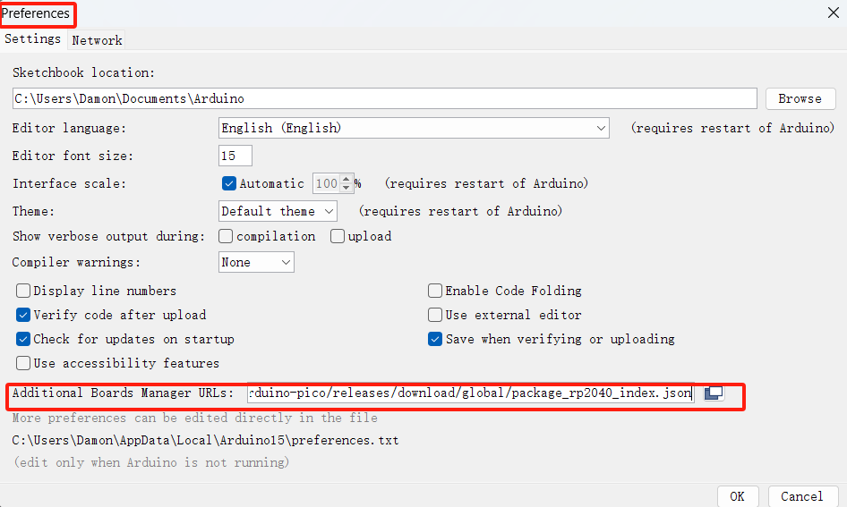
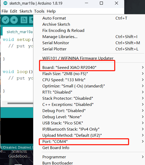
Next, I download the Raspberry Pi Pico/RP2040 from F.Philhower by going to tool, board manager and searching for pico. Then I select the “Seeed XIAO RP2040” board,And choose the right com port
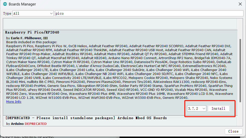
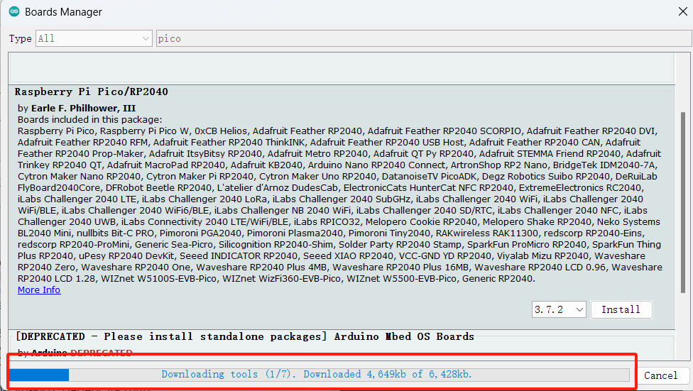
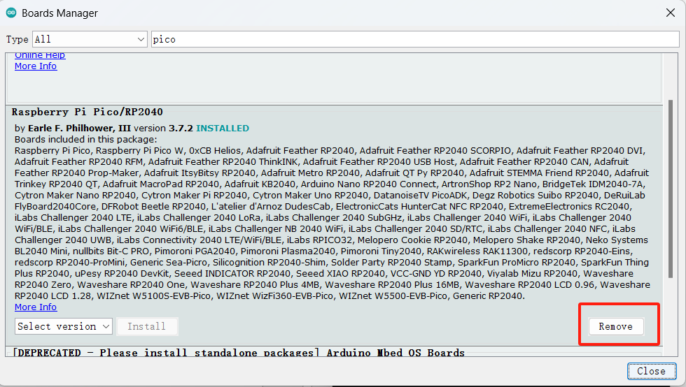
I connect the COM, which for me is 4. To test, I choose a simple ob blink test by going to file, example, basic, blink and I replace the LED_BUILTIN by 1 like this:
          void setup() {
            // initialize digital pin LED_BUILTIN as an output.
            pinMode(1, OUTPUT);
          }
          // the loop function runs over and over again forever
          void loop() {
            digitalWrite(1, HIGH);  // turn the LED on (HIGH is the voltage level)
            delay(1000);                      // wait for a second
            digitalWrite(1, LOW);   // turn the LED off by making the voltage LOW
            delay(1000);                      // wait for a second
          }



video